GB/T 44176-2024 English PDF (GBT44176-2024)
Regular price
$350.00 USD
Regular price
Sale price
$350.00 USD
Unit price
/
per
Delivery: 3 seconds. Download true-PDF + Invoice.
Get QUOTATION in 1-minute: Click GB/T 44176-2024
Historical versions: GB/T 44176-2024
Preview True-PDF (Reload/Scroll if blank)
GB/T 44176-2024: Performance requirements and testing methods for around view monitoring system of vehicles
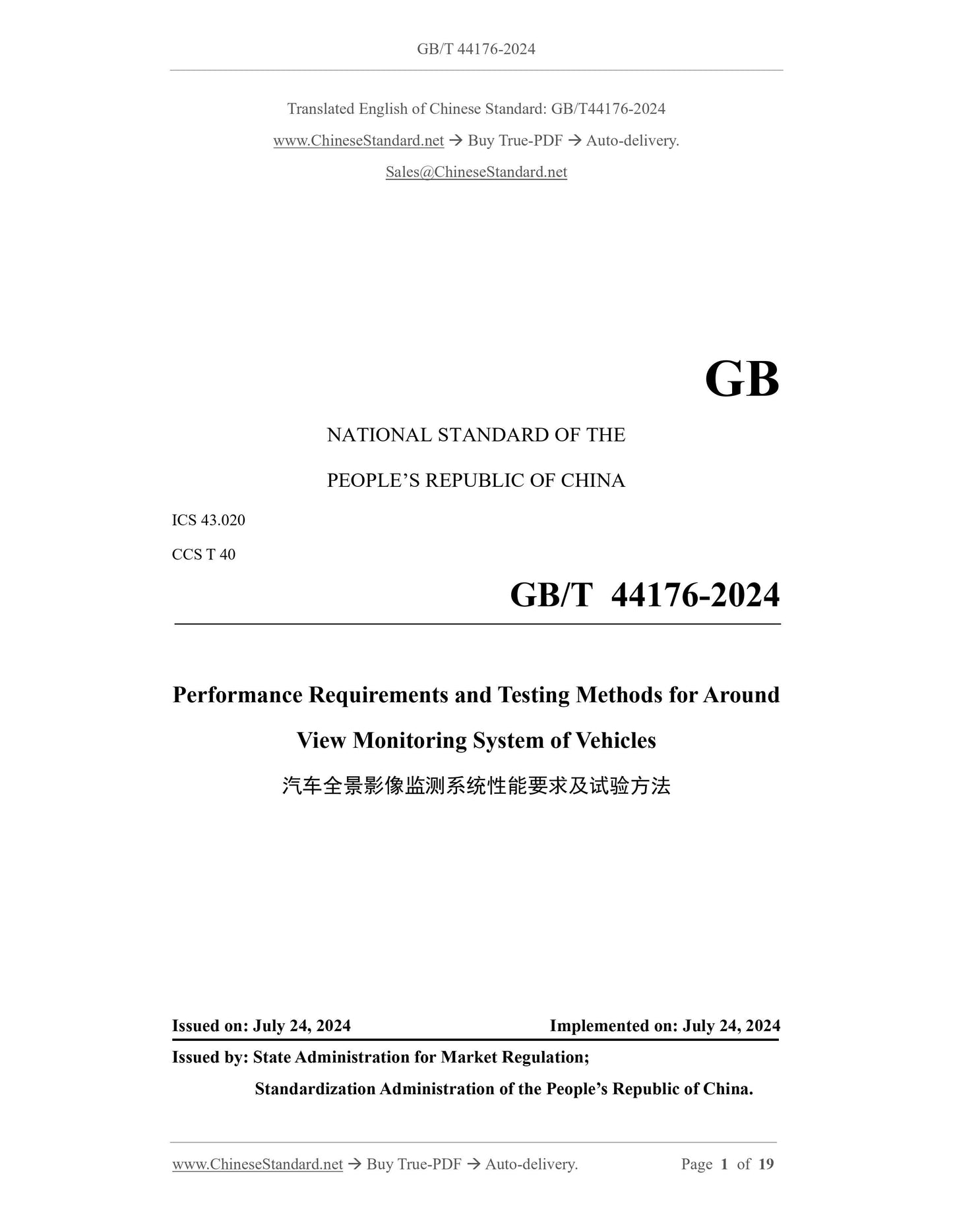
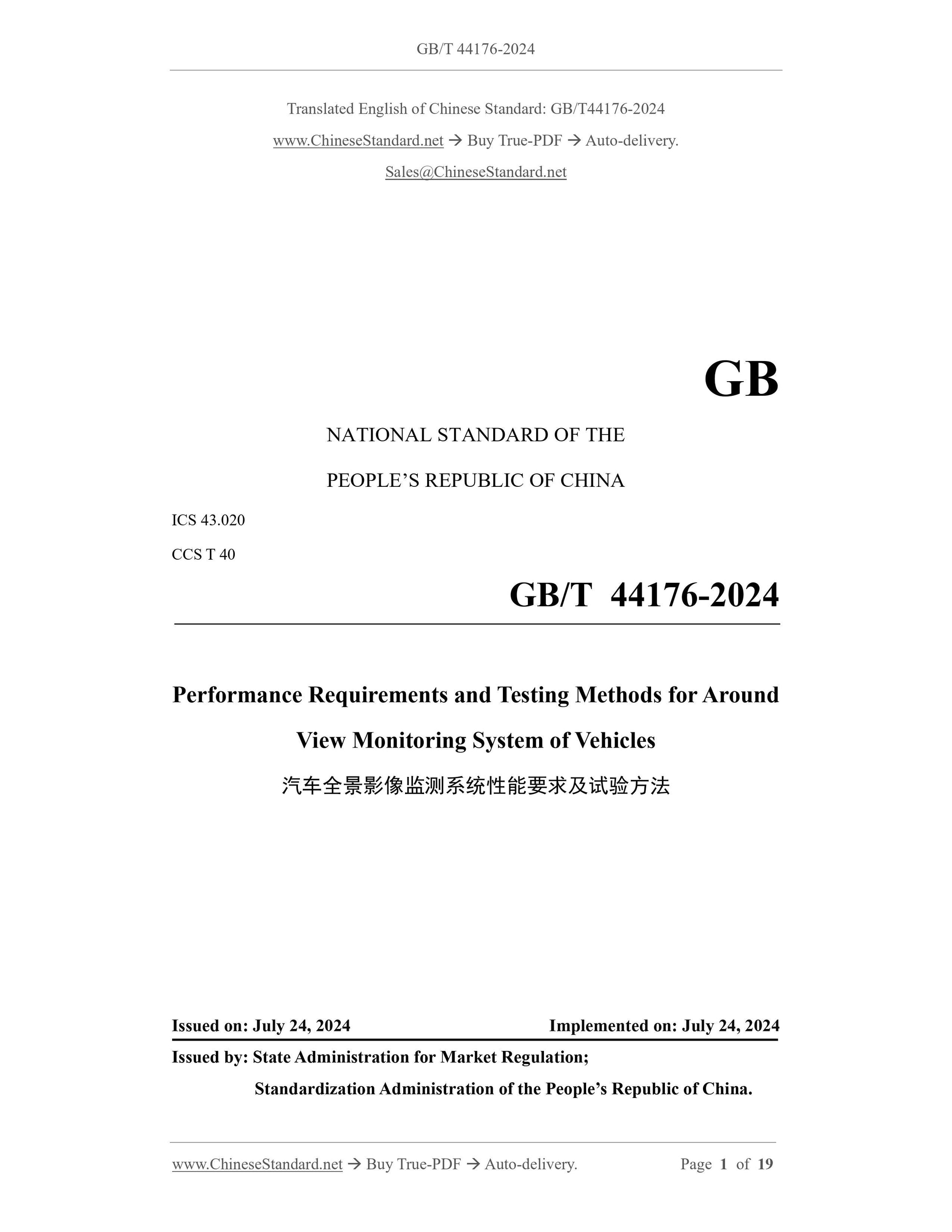
GB/T 44176-2024
GB
NATIONAL STANDARD OF THE
PEOPLE’S REPUBLIC OF CHINA
ICS 43.020
CCS T 40
Performance Requirements and Testing Methods for Around
View Monitoring System of Vehicles
ISSUED ON: JULY 24, 2024
IMPLEMENTED ON: JULY 24, 2024
Issued by: State Administration for Market Regulation;
Standardization Administration of the People’s Republic of China.
Table of Contents
Foreword ... 3
1 Scope ... 4
2 Normative References ... 4
3 Terms and Definitions ... 4
4 General Requirements ... 6
5 Performance Requirements ... 8
6 Test Method ... 11
Performance Requirements and Testing Methods for Around
View Monitoring System of Vehicles
1 Scope
This document specifies the general requirements and performance requirements for around
view monitoring system when the vehicle is stationary and driving at a low speed and describes
the test methods.
This document is applicable to Category-M and Category-N non-articulated vehicles equipped
with the around view monitoring system. Other types of vehicles may take this as a reference.
2 Normative References
The contents of the following documents constitute indispensable clauses of this document
through the normative references in the text. In terms of references with a specified date, only
versions with a specified date are applicable to this document. In terms of references without a
specified date, the latest version (including all the modifications) is applicable to this document.
GB 34660 Road Vehicles - Requirements and Test Methods of Electromagnetic Compatibility
GB/T 39263 Road Vehicles - Advanced Driver Assistance Systems - Terms and Definitions
3 Terms and Definitions
The terms and definitions defined in GB/T 39263, and the following are applicable to this
document.
3.1 around view monitoring system; AVMS
A system that provides the driver with real-time image information of the environment within
a 360 range around the vehicle.
3.2 blind spot of AVMS
Due to camera placement and vehicle structure limitations, the area around the vehicle that
cannot be monitored by the AVMS.
3.3 single view image
A view that separately displays the images collected by a certain camera.
NOTE: single view images are generally divided into front single view images, rear single view
b) The temperature range of the test environment is 20 C ~ +45 C;
c) The horizontal visibility is not less than 1 km;
d) The ambient lighting in the test area is evenly distributed and covers the field of view
of AVMS splicing; the illumination is not lower than 800 lx and not higher than
100,000 lx.
6.2 Measurement Instruments and Equipment
The measurement instruments and equipment used for testing shall satisfy the following
requirements:
a) The accuracy of the test timer is at least 0.01 s;
b) The marker used in the test of field of view of the single view image is a cylinder with
a height of 0.8 m and a diameter of 0.3 m;
c) The marker used in the test of field of view of the splicing view plane is a planar
marker with a width of 15 mm ~ 20 mm and a length of 500 mm;
d) The side length of the checkerboard graphic card cells for the test of the planar
splicing effect is 300 mm;
e) The resolution of the image acquisition equipment is not less than the resolution of
the AVMS effective display area.
6.3 Vehicle Conditions
6.3.1 Vehicle load
The test shall be carried out with the curb weight of the test vehicle plus the total mass of the
driver and the test equipment. The total mass of the driver and the test equipment shall not
exceed 150 kg. After the test starts, no adjustments to the vehicle load shall be made. For
vehicles equipped with components that may affect vehicle height, for example, adjustable air
suspension, the relevant components shall be adjusted to the exit-factory settings set by the
vehicle manufacturer.
6.3.2 Tires
The tire pressure shall be the cold-state inflation pressure recommended by the vehicle
manufacturer.
6.4 AVMS Response Time Test
The test steps are as follows:
a) Lock the vehicle, and make sure all electronic systems are disabled, or ensure that the
vehicle is locked for at least 30 minutes;
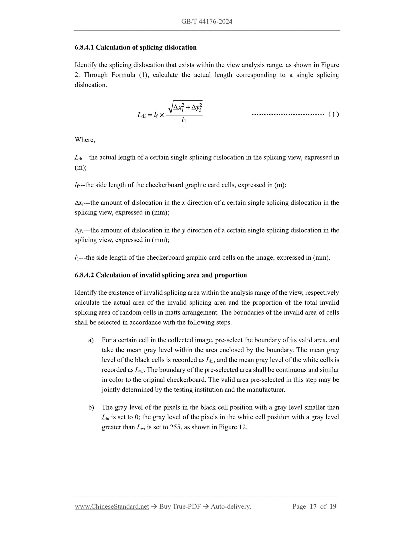
6.6 Test of Field of View of Single View Image
Activate the AVMS and adjust the steering wheel angle to 0. Switch the single view image to
the front single view image screen, at the corresponding positions shown in Figure 6 a),
respectively place the cylindrical marker, and observe whether the marker is fully displayed in
the front single view image screen.
Switch the single view image to the rear single view image, left single view image and right
single view image. At the corresponding positions shown in Figure 6 b), Figure 6 c) and Figure
6 d), respectively place the cylindrical marker, and observe whether the marker is fully
displayed in the rear single view image, left single view image and right single view image.
6.7 Test of Field of View of Splicing View Plane
Activate the AVMS and adjust the steering wheel angle to 0. On the outer edge directly in front
of the central axis of the test vehicle, perpendicular to the longitudinal axis of the test vehicle,
horizontally place a planar marker, as shown in Figure 10. Move the marker in the forward
direction of the vehicle, until the marker is fully displayed in the splicing view plane; measure
the shortest distance from the marker to the outer edge of the front end of the vehicle body at
this moment. Continue to move the marker, until the marker completely disappears in the
splicing view plane; measure the shortest distance from the marker to the outer edge of the front
end of the vehicle body at this moment.
On the outer edge of the left center and the outer edge of the right center of the vehicle parallel
to the longitudinal axis of the test vehicle, respectively place the marker; on the outer edge of
the rear center perpendicular to the longitudinal axis of the test vehicle, horizontally place the
marker. Along the direction shown in Figure 10, move the marker, and measure the shortest
distance between the complete display point and the complete disappearance point of the
marker from the outer edge of the corresponding side of the vehicle body.
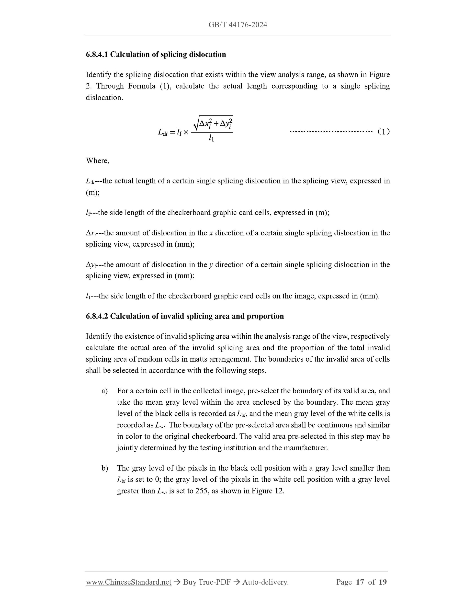
6.8.4.1 Calculation of splicing dislocation
Identify the splicing dislocation that exists within the view analysis range, as shown in Figure
2. Through Formula (1), calculate the actual length corresponding to a single splicing
dislocation.
Where,
Ldi---the actual length of a certain single splicing dislocation in the splicing view, expressed in
(m);
lf---the side length of the checkerboard graphic card cells, expressed in (m);
xi---the amount of dislocation in the x direction of a certain single splicing dislocation in the
splicing view, expressed in (mm);
yi---the amount of dislocation in the y direction of a certain single splicing dislocation in the
splicing view, expressed in (mm);
l1---the side length of the checkerboard graphic card cells on the image, expressed in (mm).
6.8.4.2 Calculation of invalid splicing area and proportion
Identify the existence of invalid splicing area within the analysis range of the view, respectively
calculate the actual area of the invalid splicing area and the proportion of the total invalid
splicing area of random cells in matts arrangement. The boundaries of the invalid area of cells
shall be selected in accordance with the following steps.
a) For a certain cell in the collected image, pre-sele...