www.ChineseStandard.us -- Field Test Asia Pte. Ltd.
GB/T 43526-2023: Technical requirements for connecting user-side electrochemical energy storage system to distribution network
Delivery: 9 seconds. Download (and Email) true-PDF + Invoice.
Get Quotation: Click
GB/T 43526-2023 (Self-service in 1-minute)
Newer / historical versions: GB/T 43526-2023Preview True-PDF
Scope
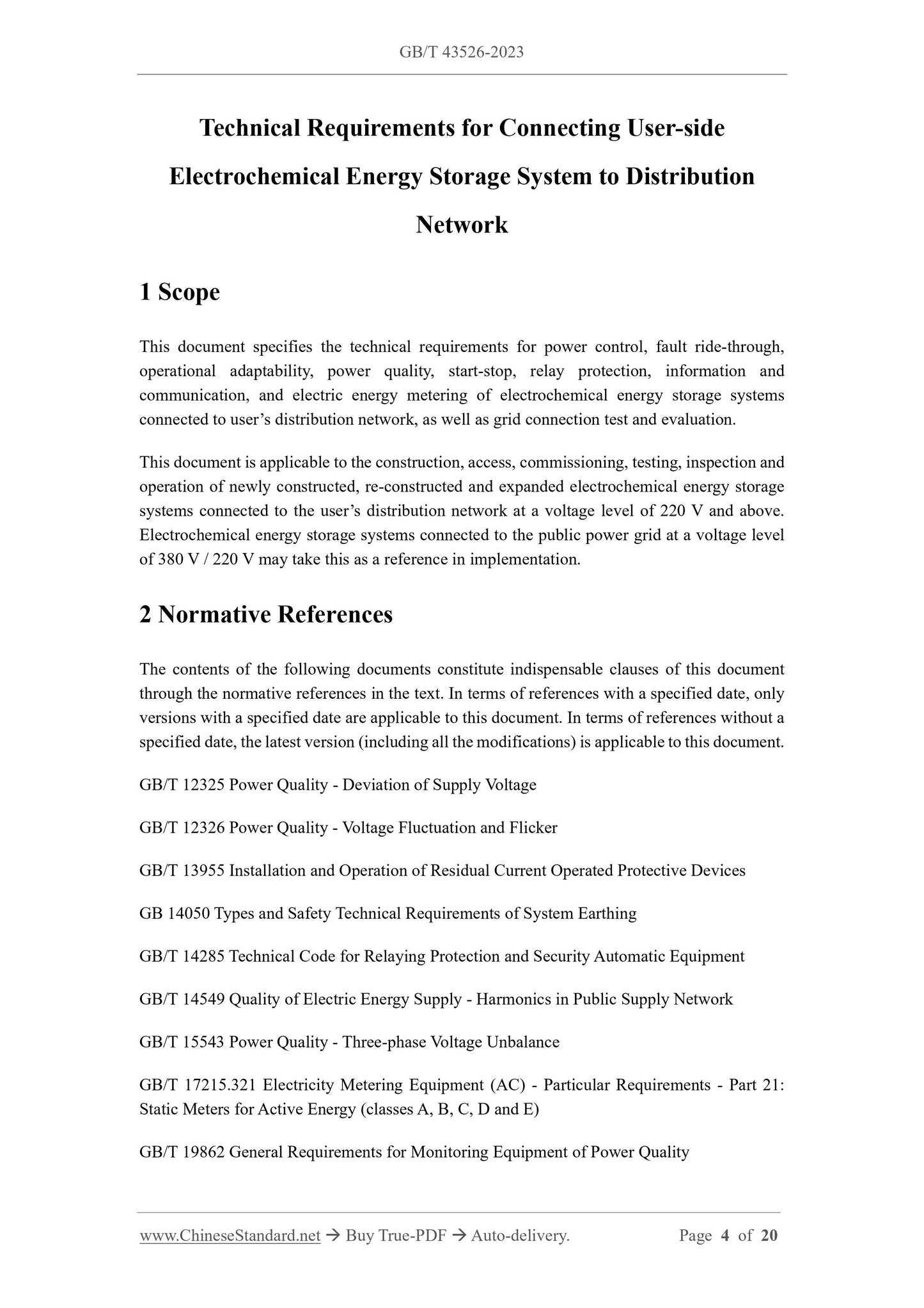
This document specifies the technical requirements for power control, fault ride-through,
operational adaptability, power quality, start-stop, relay protection, information and
communication, and electric energy metering of electrochemical energy storage systems
connected to user’s distribution network, as well as grid connection test and evaluation.
This document is applicable to the construction, access, commissioning, testing, inspection and
operation of newly constructed, re-constructed and expanded electrochemical energy storage
systems connected to the user’s distribution network at a voltage level of 220 V and above.
Electrochemical energy storage systems connected to the public power grid at a voltage level
of 380 V / 220 V may take this as a reference in implementation.
Basic Data
| Standard ID | GB/T 43526-2023 (GB/T43526-2023) |
| Description (Translated English) | Technical requirements for connecting user-side electrochemical energy storage system to distribution network |
| Sector / Industry | National Standard (Recommended) |
| Classification of Chinese Standard | F19 |
| Classification of International Standard | 27.180 |
| Word Count Estimation | 14,113 |
| Date of Issue | 2023-12-28 |
| Date of Implementation | 2024-07-01 |
| Issuing agency(ies) | State Administration for Market Regulation, China National Standardization Administration |