Skip to product information
1 of 8

www.ChineseStandard.us -- Field Test Asia Pte. Ltd.

GB/T 43496-2023 English PDF (GB/T43496-2023)

GB/T 43496-2023 English PDF (GB/T43496-2023)

Regular price $275.00
Regular price Sale price $275.00
Sale Sold out
Shipping calculated at checkout.
GB/T 43496-2023: Test method of thermal cycling and condensation resistance of curtain walls
Delivery: 9 seconds. Download (& Email) true-PDF + Invoice.
Get Quotation: Click GB/T 43496-2023 (Self-service in 1-minute)
Historical versions (Master-website): GB/T 43496-2023
Preview True-PDF (Reload/Scroll-down if blank)

GB/T 43496-2023
GB
NATIONAL STANDARD OF THE
PEOPLE’S REPUBLIC OF CHINA
ICS 91.060.10
CCS P 32
GB/T 43496-2023
Test method of thermal cycling and condensation resistance
of curtain walls
ISSUED ON. DECEMBER 28, 2023
IMPLEMENTED ON. JULY 01, 2024
Issued by. State Administration for Market Regulation;
Standardization Administration of the People’s Republic of China.
Table of Contents
Foreword... 3
1 Scope... 5
2 Normative references... 5
3 Terms and definitions... 5
4 General requirements... 7
5 Test principle... 8
6 Test apparatus... 8
6.1 Composition... 8
6.2 Requirements... 9
7 Test piece and installation... 10
7.1 Test piece... 10
7.2 Installation and inspection... 11
8 Test method... 11
8.1 Test sequence... 11
8.2 Airtightness... 11
8.3 Watertightness... 11
8.4 Thermal cycle... 11
8.5 Condensation... 14
8.6 Repeated airtightness... 15
8.7 Repeated watertightness... 15
8.8 Result evaluation... 15
9 Test report... 16
Test method of thermal cycling and condensation resistance
of curtain walls
1 Scope
This document specifies the general requirements, test principle, test apparatus, test
piece and installation, test method and test report for the test method of thermal cycling
and condensation resistance of curtain walls.
This document applies to the laboratory test of thermal cycle and condensation of
curtain walls. The test objects are limited to the curtain wall test pieces themselves and
the connection structure between them and the structure.
2 Normative references
The following referenced documents are indispensable for the application of this
document. For dated references, only the edition cited applies. For undated references,
the latest edition of the referenced document (including any amendments) applies.
GB/T 15227 Test method of air permeability, watertightness, wind load resistance
performance for curtain walls
GB/T 31433 General specification for building curtain walls, windows and doors
GB/T 34327 Terminology for curtain wall
3 Terms and definitions
For the purpose of this document, the terms and definitions defined in GB/T 34327 and
the following apply.
3.1
thermal cycle
Process of simulating the cyclical changes of specific natural climate conditions outside
the test piece.
NOTE. The simulated conditions include air temperature and solar thermal radiation illumination.
3.2
Key.
1 - outdoor side insulation box;
2 - guide plate;
3 - infrared radiation heating device;
4 - outdoor side air circulation system;
5 - outdoor side air temperature control device;
6 - indoor side air temperature and humidity control device;
7 - indoor side air circulation system;
8 - indoor side insulation box;
9 - test piece;
10 - test piece installation support device;
11 - connection structure.
Figure 1 -- Schematic diagram of test apparatus
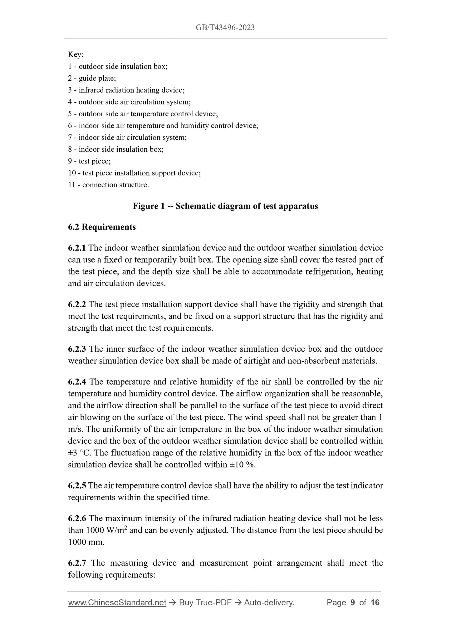
6.2 Requirements
6.2.1 The indoor weather simulation device and the outdoor weather simulation device
can use a fixed or temporarily built box. The opening size shall cover the tested part of
the test piece, and the depth size shall be able to accommodate refrigeration, heating
and air circulation devices.
6.2.2 The test piece installation support device shall have the rigidity and strength that
meet the test requirements, and be fixed on a support structure that has the rigidity and
strength that meet the test requirements.
6.2.3 The inner surface of the indoor weather simulation device box and the outdoor
weather simulation device box shall be made of airtight and non-absorbent materials.
6.2.4 The temperature and relative humidity of the air shall be controlled by the air
temperature and humidity control device. The airflow organization shall be reasonable,
and the airflow direction shall be parallel to the surface of the test piece to avoid direct
air blowing on the surface of the test piece. The wind speed shall not be greater than 1
m/s. The uniformity of the air temperature in the box of the indoor weather simulation
device and the box of the outdoor weather simulation device shall be controlled within
±3 ℃. The fluctuation range of the relative humidity in the box of the indoor weather
simulation device shall be controlled within ±10 %.
6.2.5 The air temperature control device shall have the ability to adjust the test indicator
requirements within the specified time.
6.2.6 The maximum intensity of the infrared radiation heating device shall not be less
than 1000 W/m2 and can be evenly adjusted. The distance from the test piece should be
1000 mm.
6.2.7 The measuring device and measurement point arrangement shall meet the
following requirements.
a) the accuracy of the temperature sensor shall be within ±2 ℃;
b) the accuracy of the humidity sensor shall be within ±5 %;
c) the temperature sensors for the air temperature in the box shall be arranged in
representative areas of the box, at least the four corners and the center of the box
close to the test piece. The sensors shall be shielded from radiation and the
distance from the test piece shall not be less than 80 mm;
d) the humidity sensor for the indoor side air relative humidity shall be arranged near
the return air outlet of the box;
e) the temperature sensors for the internal and external surface temperatures of the
test piece shall be arranged on the surface of the panel and profile, the induction
head together with the lead shall be close to the measured surface, and the lead
length shall not be less than 100 mm; the total hemispherical emissivity of the
adhesive material shall be close to the value of the measured surface;
f) the temperature measurement points on the test piece shall be arranged on the
supporting members and the panel members; for bar members, they shall be
arranged at the two ends and the middle, and for panels, they shall be arranged at
the midpoints of the two long sides and the center of the panel.
7 Test piece and installation
7.1 Test piece
7.1.1 The test piece shall represent the performance of typical parts of the curtain wall,
including typical vertical joints, horizontal joints and openable fields. The proportion
of the openable fields to the total area of the test piece shall be close to the actual project.
7.1.2 The material, specification and model of the test piece shall be consistent with the
corresponding information provided by the test client.
7.1.3 The width of the test piece shall include at least one vertical load-bearing member
that bears the design load. The height of the test piece shall include at least one floor
height, and there shall be two or more vertical connections with the load-bearing
structure.
7.1.4 The full-glass curtain wall test piece shall have a full span height and a width of
at least 3 glass horizontal divisions or 4 glass ribs.
7.1.5 The height of the unitized curtain wall test piece shall not be less than 2 floor
heights, and the width shall not be less than 3 horizontal divisions.
7.1.6 The test piece of double-skin curtain walls shall meet the following requirements.
Within the specified time, by simulating the annual cyclical changes of outdoor weather
air temperature, solar radiation, and indoor temperature and humidity environment,
observe whether there are functional disorders, component damage, and whether
condensation occurs at low temperatures.
8.4.2 Test method and selection
For those with only outdoor air temperature requirements, the “air temperature method”
(method 1) is used; for those with test piece surface temperature requirements, the
“surface temperature method” (method 2) is used.
8.4.3 Air temperature method (method 1)
Before the thermal cycle test, adjust the indoor side air temperature and relative
humidity to the indoor side indicator values and maintained for not less than 1 h. Then
proceed as follows.
a) steadily increase the outdoor side air temperature to the specified outdoor
maximum air temperature Tamax in 0.5 h ~ 1 h, and the maintenance time shall not
be less than 2 h.
b) steadily reduce the outdoor side air temperature to the indoor air temperature Tin
in 0.5 h ~ 1 h.
c) steadily reduce the outdoor side air temperature to the specified outdoor minimum
air temperature Tamin in 0.5 h ~ 1 h, and the maintenance time shall not be less
than 2 h.
d) steadily increase the outdoor side air temperature to the indoor air temperature Tin
in 0.5 h ~ 1 h.
e) repeat steps a) ~ d), the number of cycles shall not be less than 6 times, and the
schematic diagram of thermal cycle test cycle is shown in Figure 2.
f) keep the indoor side air temperature and relative humidity stable during the test.
In each low-temperature and high-temperature holding stage, check whether the
test piece is damaged on the indoor side; after the test is completed, check whether
the test piece has damage or functional disorder.
8.4.5 Requirements for the test process
The test process shall meet the following requirements.
a) in each control stage of a cycle, the fluctuation range of indoor and outdoor air
temperature is not more than 3 ℃, and the fluctuation range of indoor air relative
humidity is not more than 10 %;
b) for the indoor side, the data collection interval of air temperature and relative
humidity is not more than 20 min;
c) for the outdoor side, the data collection interval of air temperature or test piece
surface temperature is not more than 2 min.
8.5 Condensation
8.5.1 Test content
Maintain stable indoor temperature and relative humidity within the specified time,
simulate the low temperature outdoor at the same time, and maintain for 12 h. After the
process is completed, observe whether the test piece has functional disorders,
component damage, condensation, etc.
8.5.2 Test method
The test shall be carried out according to the following steps.
a) adjust the indoor side air temperature and relative humidity to the indicator values
and keep them stable;
b) steadily reduce the outdoor side air temperature to the specified outdoor minimum
air temperature Tamin within 1 h, and maintain it for 12 h;
c) steadily increase the outdoor side air temperature to the indoor air temperature Tin
within 1 h; see Figure 3 for the schematic diagram of condensation test;
d) check whether the test piece has damage or functional disorder on the indoor side,
observe and record the condensation status and location according to Table 1.
GB/T 43496-2023
GB
NATIONAL STANDARD OF THE
PEOPLE’S REPUBLIC OF CHINA
ICS 91.060.10
CCS P 32
GB/T 43496-2023
Test method of thermal cycling and condensation resistance
of curtain walls
ISSUED ON. DECEMBER 28, 2023
IMPLEMENTED ON. JULY 01, 2024
Issued by. State Administration for Market Regulation;
Standardization Administration of the People’s Republic of China.
Table of Contents
Foreword... 3
1 Scope... 5
2 Normative references... 5
3 Terms and definitions... 5
4 General requirements... 7
5 Test principle... 8
6 Test apparatus... 8
6.1 Composition... 8
6.2 Requirements... 9
7 Test piece and installation... 10
7.1 Test piece... 10
7.2 Installation and inspection... 11
8 Test method... 11
8.1 Test sequence... 11
8.2 Airtightness... 11
8.3 Watertightness... 11
8.4 Thermal cycle... 11
8.5 Condensation... 14
8.6 Repeated airtightness... 15
8.7 Repeated watertightness... 15
8.8 Result evaluation... 15
9 Test report... 16
Test method of thermal cycling and condensation resistance
of curtain walls
1 Scope
This document specifies the general requirements, test principle, test apparatus, test
piece and installation, test method and test report for the test method of thermal cycling
and condensation resistance of curtain walls.
This document applies to the laboratory test of thermal cycle and condensation of
curtain walls. The test objects are limited to the curtain wall test pieces themselves and
the connection structure between them and the structure.
2 Normative references
The following referenced documents are indispensable for the application of this
document. For dated references, only the edition cited applies. For undated references,
the latest edition of the referenced document (including any amendments) applies.
GB/T 15227 Test method of air permeability, watertightness, wind load resistance
performance for curtain walls
GB/T 31433 General specification for building curtain walls, windows and doors
GB/T 34327 Terminology for curtain wall
3 Terms and definitions
For the purpose of this document, the terms and definitions defined in GB/T 34327 and
the following apply.
3.1
thermal cycle
Process of simulating the cyclical changes of specific natural climate conditions outside
the test piece.
NOTE. The simulated conditions include air temperature and solar thermal radiation illumination.
3.2
Key.
1 - outdoor side insulation box;
2 - guide plate;
3 - infrared radiation heating device;
4 - outdoor side air circulation system;
5 - outdoor side air temperature control device;
6 - indoor side air temperature and humidity control device;
7 - indoor side air circulation system;
8 - indoor side insulation box;
9 - test piece;
10 - test piece installation support device;
11 - connection structure.
Figure 1 -- Schematic diagram of test apparatus
6.2 Requirements
6.2.1 The indoor weather simulation device and the outdoor weather simulation device
can use a fixed or temporarily built box. The opening size shall cover the tested part of
the test piece, and the depth size shall be able to accommodate refrigeration, heating
and air circulation devices.
6.2.2 The test piece installation support device shall have the rigidity and strength that
meet the test requirements, and be fixed on a support structure that has the rigidity and
strength that meet the test requirements.
6.2.3 The inner surface of the indoor weather simulation device box and ...
View full details