Skip to product information
1 of 12

PayPal, credit cards. Download editable-PDF and invoice in 1 second!

GB/T 43408-2023 English PDF (GBT43408-2023)

GB/T 43408-2023 English PDF (GBT43408-2023)

Regular price $575.00 USD
Regular price Sale price $575.00 USD
Sale Sold out
Shipping calculated at checkout.
Delivery: 3 seconds. Download true-PDF + Invoice.
Get QUOTATION in 1-minute: Click GB/T 43408-2023
Historical versions: GB/T 43408-2023
Preview True-PDF (Reload/Scroll if blank)

GB/T 43408-2023: Road vehicles -- Compressed natural gas (CNG) refuelling connector
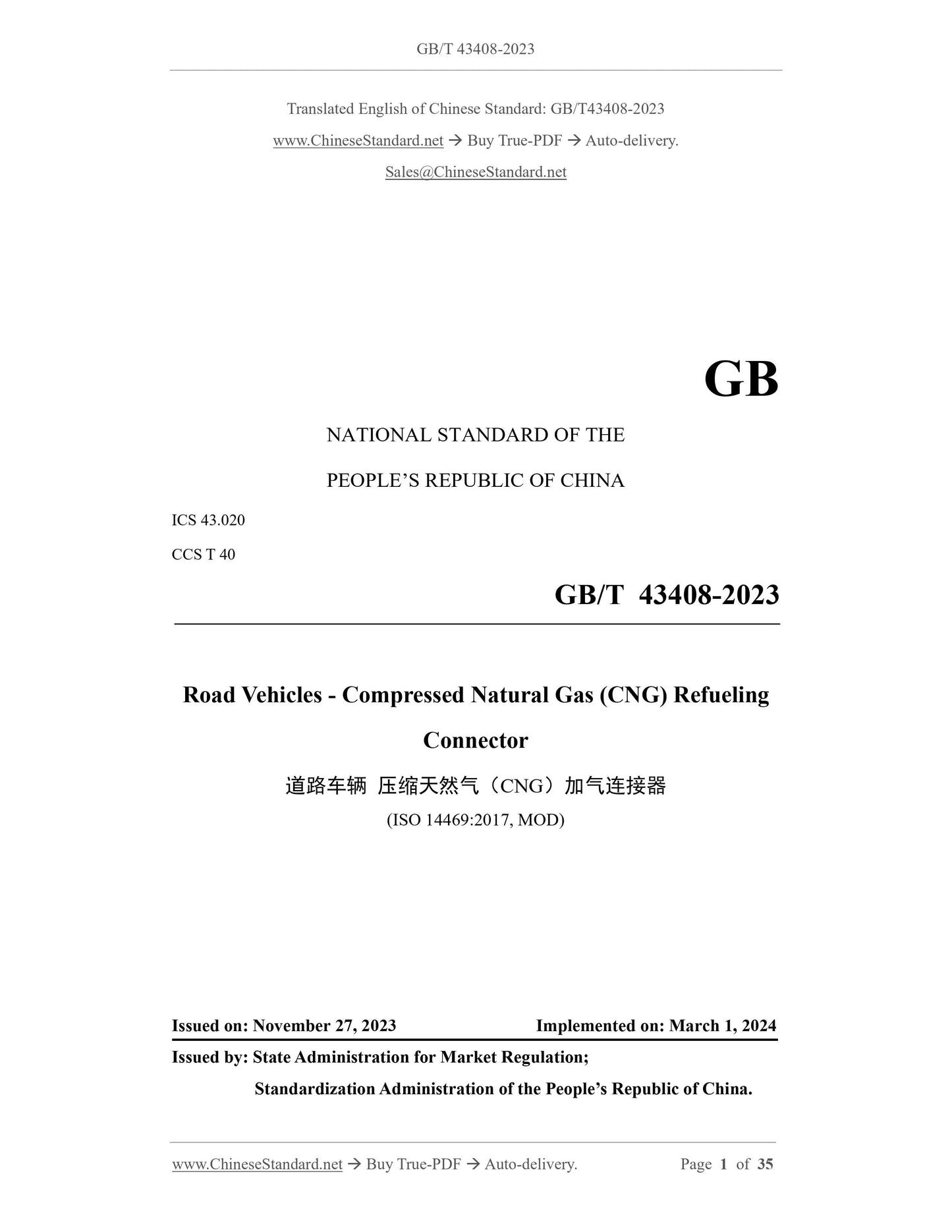
GB/T 43408-2023
GB
NATIONAL STANDARD OF THE
PEOPLE’S REPUBLIC OF CHINA
ICS 43.020
CCS T 40
Road Vehicles - Compressed Natural Gas (CNG) Refueling
Connector
(ISO 14469:2017, MOD)
ISSUED ON: NOVEMBER 27, 2023
IMPLEMENTED ON: MARCH 1, 2024
Issued by: State Administration for Market Regulation;
Standardization Administration of the People’s Republic of China.
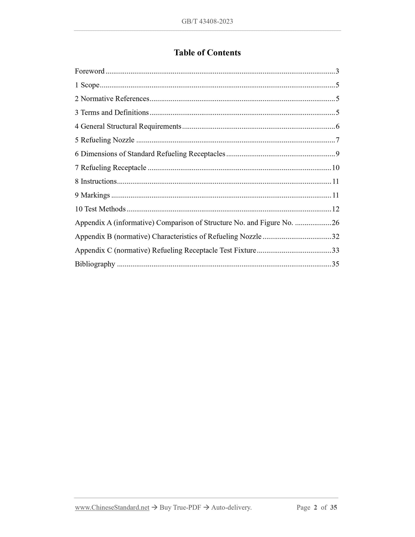
Table of Contents
Foreword ... 3
1 Scope ... 5
2 Normative References ... 5
3 Terms and Definitions ... 5
4 General Structural Requirements ... 6
5 Refueling Nozzle ... 7
6 Dimensions of Standard Refueling Receptacles ... 9
7 Refueling Receptacle ... 10
8 Instructions ... 11
9 Markings ... 11
10 Test Methods ... 12
Appendix A (informative) Comparison of Structure No. and Figure No... 26
Appendix B (normative) Characteristics of Refueling Nozzle ... 32
Appendix C (normative) Refueling Receptacle Test Fixture ... 33
Bibliography ... 35
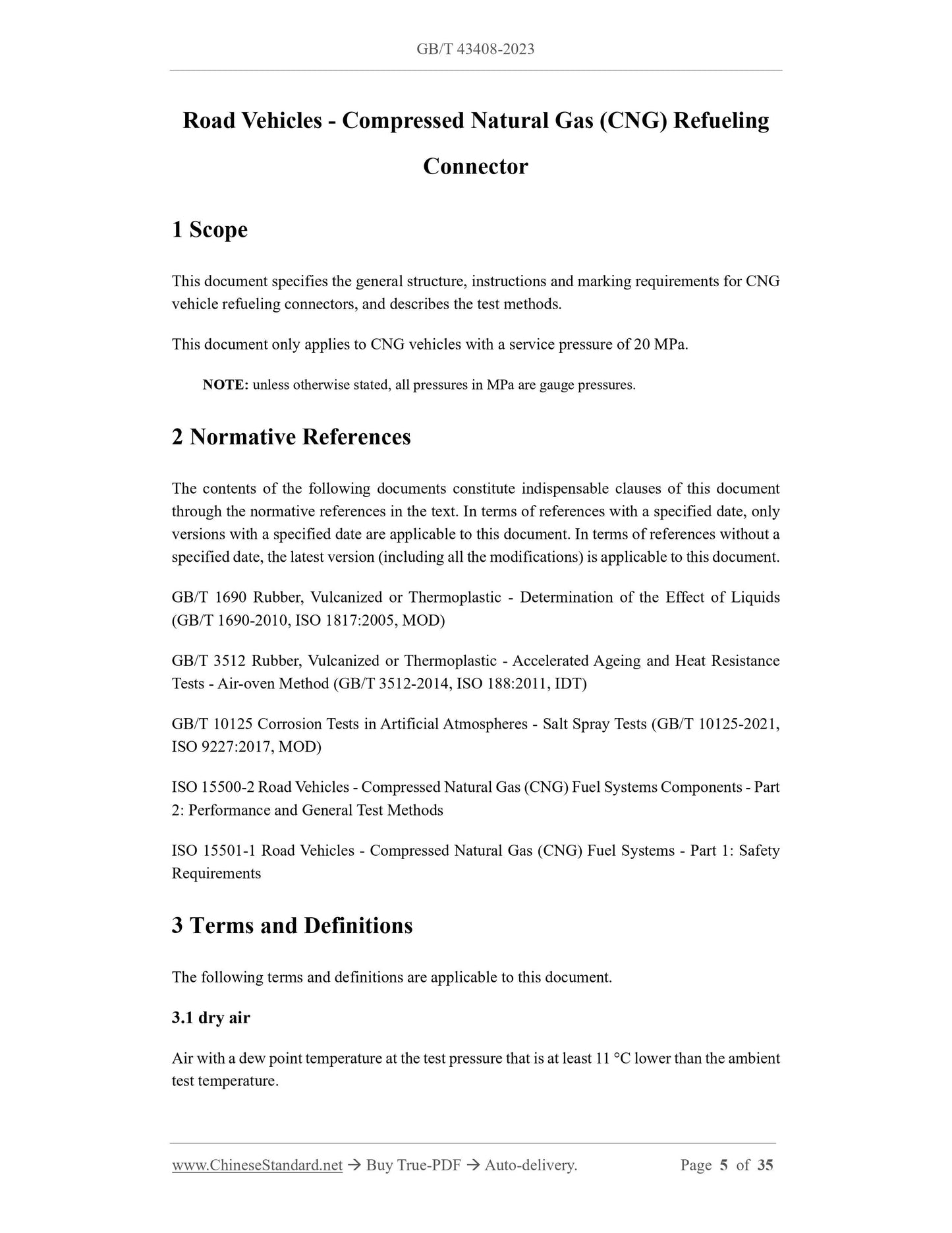
Road Vehicles - Compressed Natural Gas (CNG) Refueling
Connector
1 Scope
This document specifies the general structure, instructions and marking requirements for CNG
vehicle refueling connectors, and describes the test methods.
This document only applies to CNG vehicles with a service pressure of 20 MPa.
NOTE: unless otherwise stated, all pressures in MPa are gauge pressures.
2 Normative References
The contents of the following documents constitute indispensable clauses of this document
through the normative references in the text. In terms of references with a specified date, only
versions with a specified date are applicable to this document. In terms of references without a
specified date, the latest version (including all the modifications) is applicable to this document.
GB/T 1690 Rubber, Vulcanized or Thermoplastic - Determination of the Effect of Liquids
(GB/T 1690-2010, ISO 1817:2005, MOD)
GB/T 3512 Rubber, Vulcanized or Thermoplastic - Accelerated Ageing and Heat Resistance
Tests - Air-oven Method (GB/T 3512-2014, ISO 188:2011, IDT)
GB/T 10125 Corrosion Tests in Artificial Atmospheres - Salt Spray Tests (GB/T 10125-2021,
ISO 9227:2017, MOD)
ISO 15500-2 Road Vehicles - Compressed Natural Gas (CNG) Fuel Systems Components - Part
2: Performance and General Test Methods
ISO 15501-1 Road Vehicles - Compressed Natural Gas (CNG) Fuel Systems - Part 1: Safety
Requirements
3 Terms and Definitions
The following terms and definitions are applicable to this document.
3.1 dry air
Air with a dew point temperature at the test pressure that is at least 11 C lower than the ambient
test temperature.
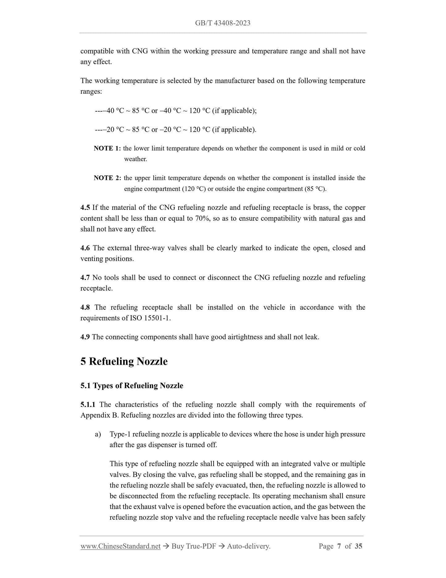
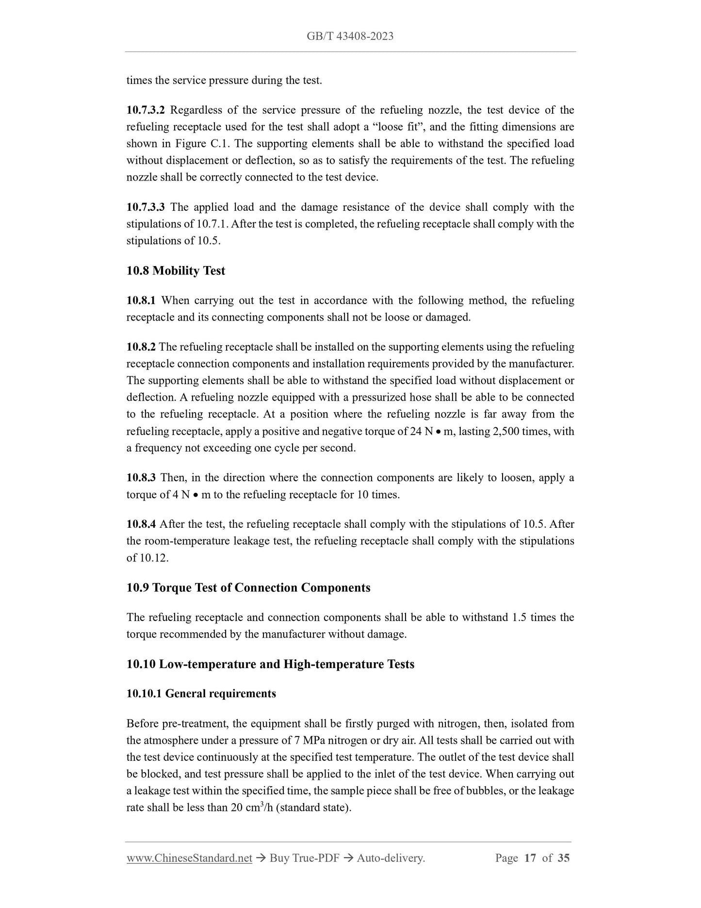
compatible with CNG within the working pressure and temperature range and shall not have
any effect.
The working temperature is selected by the manufacturer based on the following temperature
ranges:
---40 C ~ 85 C or 40 C ~ 120 C (if applicable);
---20 C ~ 85 C or 20 C ~ 120 C (if applicable).
NOTE 1: the lower limit temperature depends on whether the component is used in mild or cold
weather.
NOTE 2: the upper limit temperature depends on whether the component is installed inside the
engine compartment (120 C) or outside the engine compartment (85 C).
4.5 If the material of the CNG refueling nozzle and refueling receptacle is brass, the copper
content shall be less than or equal to 70%, so as to ensure compatibility with natural gas and
shall not have any effect.
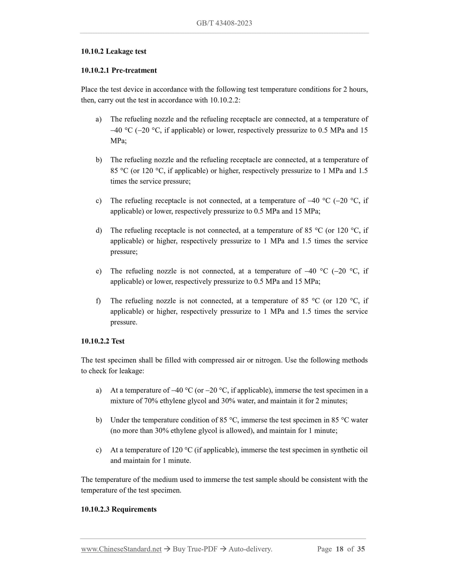
4.6 The external three-way valves shall be clearly marked to indicate the open, closed and
venting positions.
4.7 No tools shall be used to connect or disconnect the CNG refueling nozzle and refueling
receptacle.
4.8 The refueling receptacle shall be installed on the vehicle in accordance with the
requirements of ISO 15501-1.
4.9 The connecting components shall have good airtightness and shall not leak.
5 Refueling Nozzle
5.1 Types of Refueling Nozzle
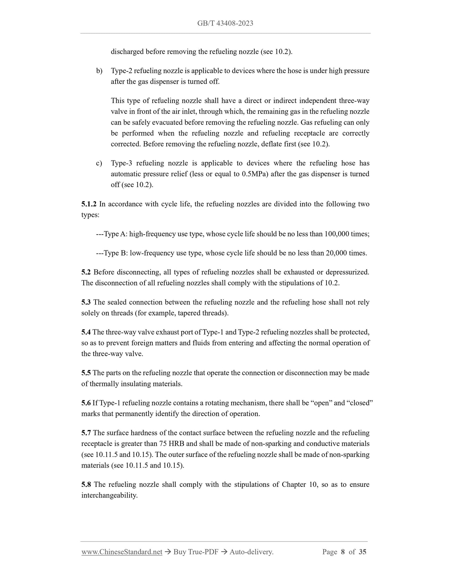
5.1.1 The characteristics of the refueling nozzle shall comply with the requirements of
Appendix B. Refueling nozzles are divided into the following three types.
a) Type-1 refueling nozzle is applicable to devices where the hose is under high pressure
after the gas dispenser is turned off.
This type of refueling nozzle shall be equipped with an integrated valve or multiple
valves. By closing the valve, gas refueling shall be stopped, and the remaining gas in
the refueling nozzle shall be safely evacuated, then, the refueling nozzle is allowed to
be disconnected from the refueling receptacle. Its operating mechanism shall ensure
that the exhaust valve is opened before the evacuation action, and the gas between the
refueling nozzle stop valve and the refueling receptacle needle valve has been safely
discharged before removing the refueling nozzle (see 10.2).
b) Type-2 refueling nozzle is applicable to devices where the hose is under high pressure
after the gas dispenser is turned off.
This type of refueling nozzle shall have a direct or indirect independent three-way
valve in front of the air inlet, through which, the remaining gas in the refueling nozzle
can be safely evacuated before removing the refueling nozzle. Gas refueling can only
be performed when the refueling nozzle and refueling receptacle are correctly
corrected. Before removing the refueling nozzle, deflate first (see 10.2).
c) Type-3 refueling nozzle is applicable to devices where the refueling hose has
automatic pressure relief (less or equal to 0.5MPa) after the gas dispenser is turned
off (see 10.2).
5.1.2 In accordance with cycle life, the refueling nozzles are divided into the following two
types:
---Type A: high-frequency use type, whose cycle life should be no less than 100,000 times;
---Type B: low-frequency use type, whose cycle life should be no less than 20,000 times.
5.2 Before disconnecting, all types of refueling nozzles shall be exhausted or depressurized.
The disconnection of all refueling nozzles shall comply with the stipulations of 10.2.
5.3 The sealed connection between the refueling nozzle and the refueling hose shall not rely
solely on threads (for example, tapered threads).
5.4 The three-way valve exhaust port of Type-1 and Type-2 refueling nozzles shall be protected,
so as to prevent foreign matters and fluids from entering and affecting the normal operation of
the three-way valve.
5.5 The parts on the refueling nozzle that operate the connection or disconnection may be made
of thermally insulating materials.
5.6 If Type-1 refueling nozzle contains a rotating mechanism, there shall be “open” and “closed”
marks that permanently identify the direction of operation.
5.7 The surface hardness of the contact surface between the refueling nozzle and the refueling
receptacle is greater than 75 HRB and shall be made of non-sparking and conductive materials
(see 10.11.5 and 10.15). The outer surface of the refueling nozzle shall be made of non-sparking
materials (see 10.11.5 and 10.15).
5.8 The refueling nozzle shall comply with the stipulations of Chapter 10, so as to ensure
interchangeability.
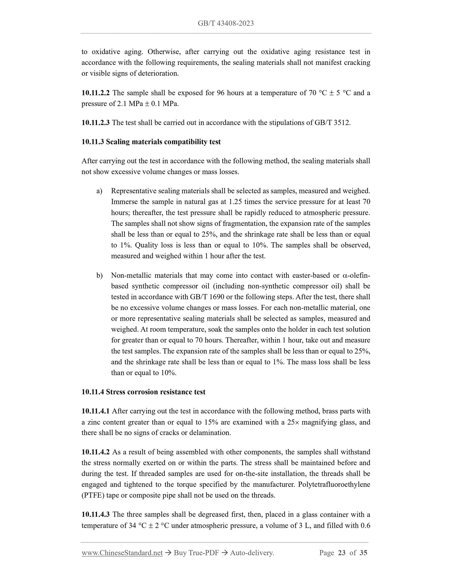
c) B200;
d) Applicable types and categories (see 5.1);
e) Working temperature range.
9.3 The refueling nozzle and refueling receptacle shall be marked with a manufacturing date
code.
9.4 Each system shall have identification consistent with this document, which may be located
on the equipment, on the packaging, or in the documentation included in the equipment’s exit-
factory packaging.
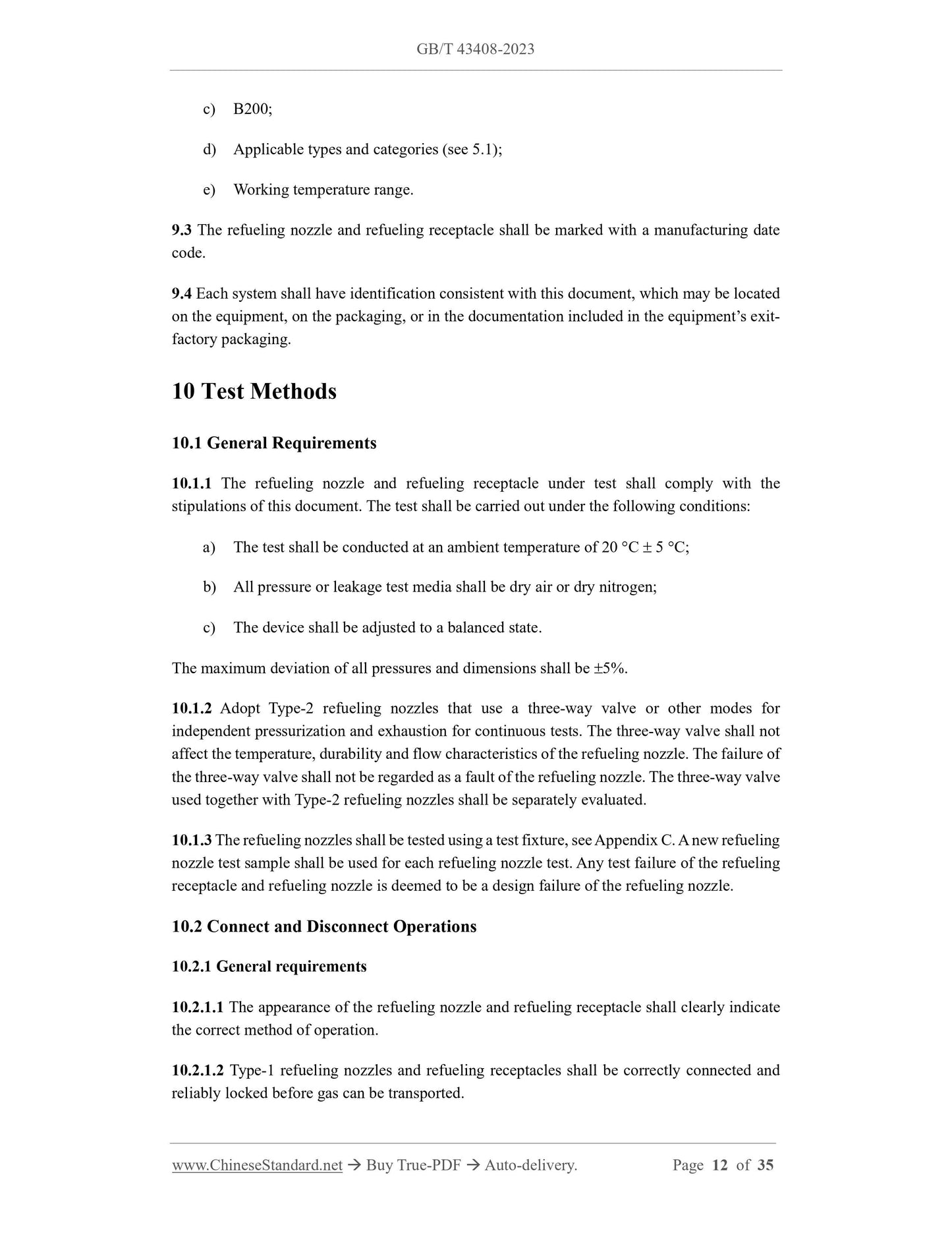
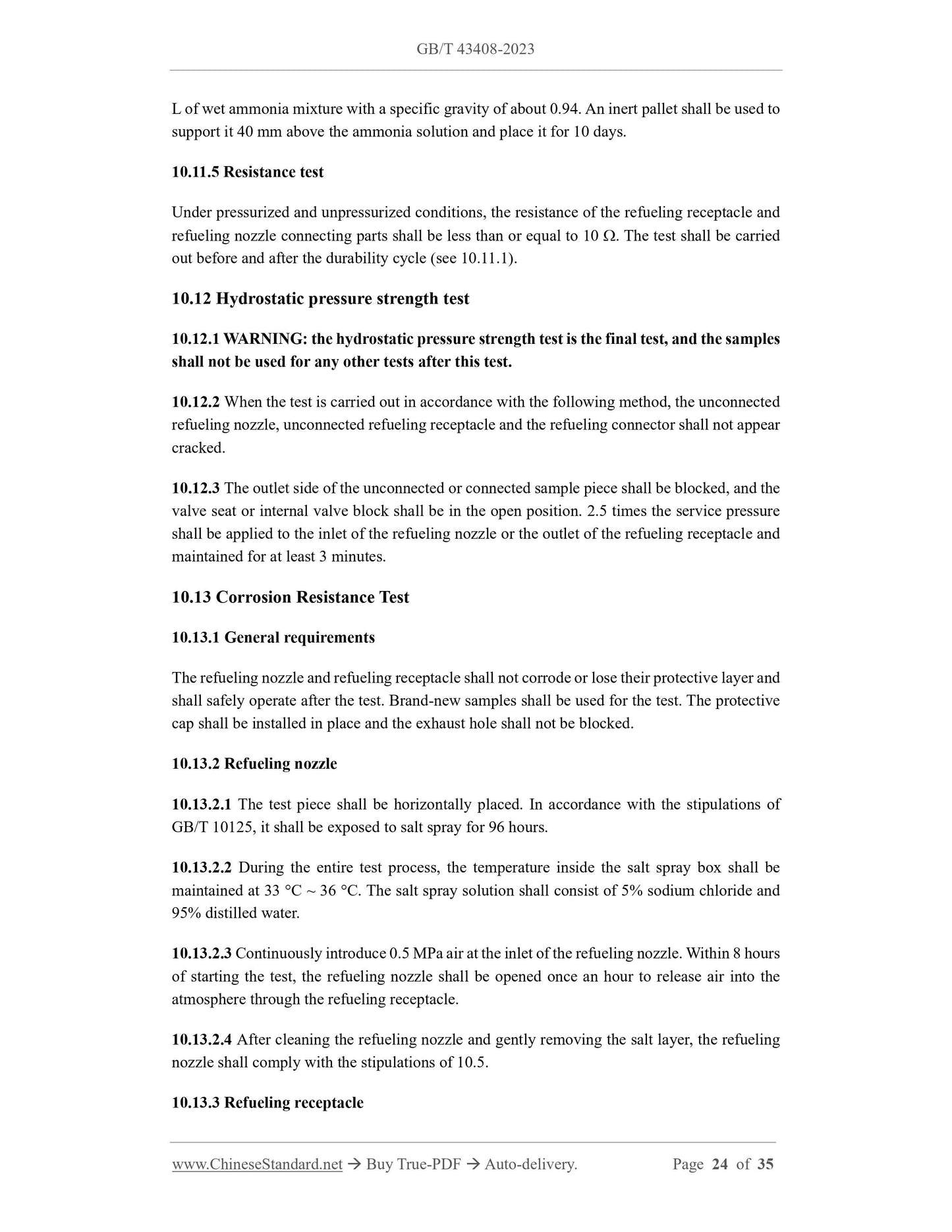
10 Test Methods
10.1 General Requirements
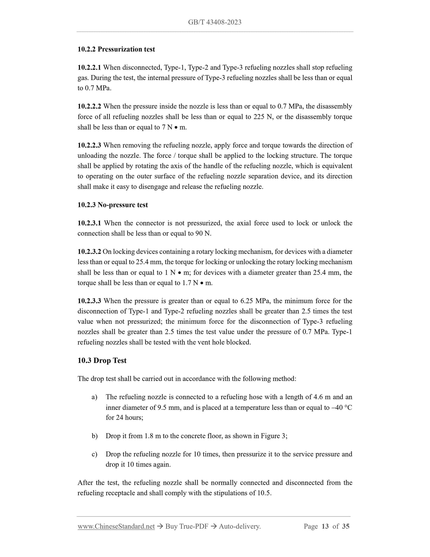
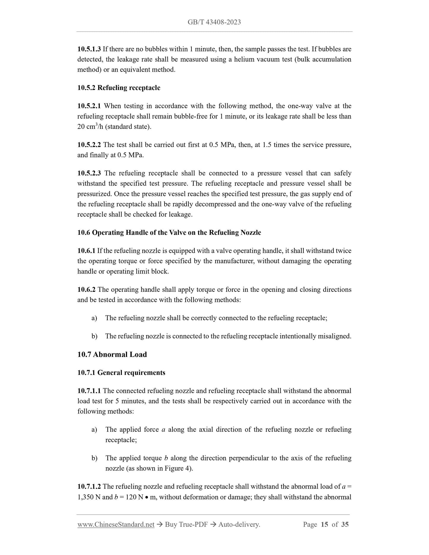
10.1.1 The refueling nozzl...
View full details