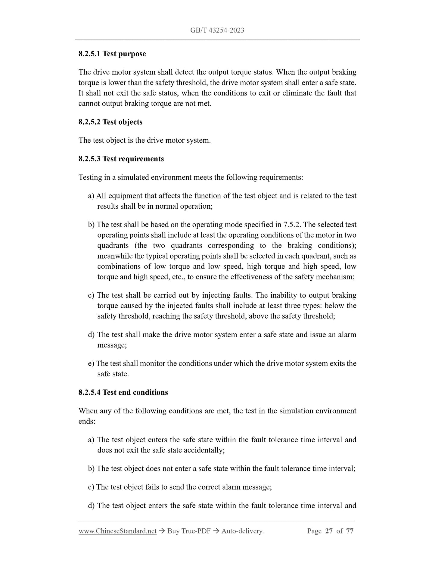
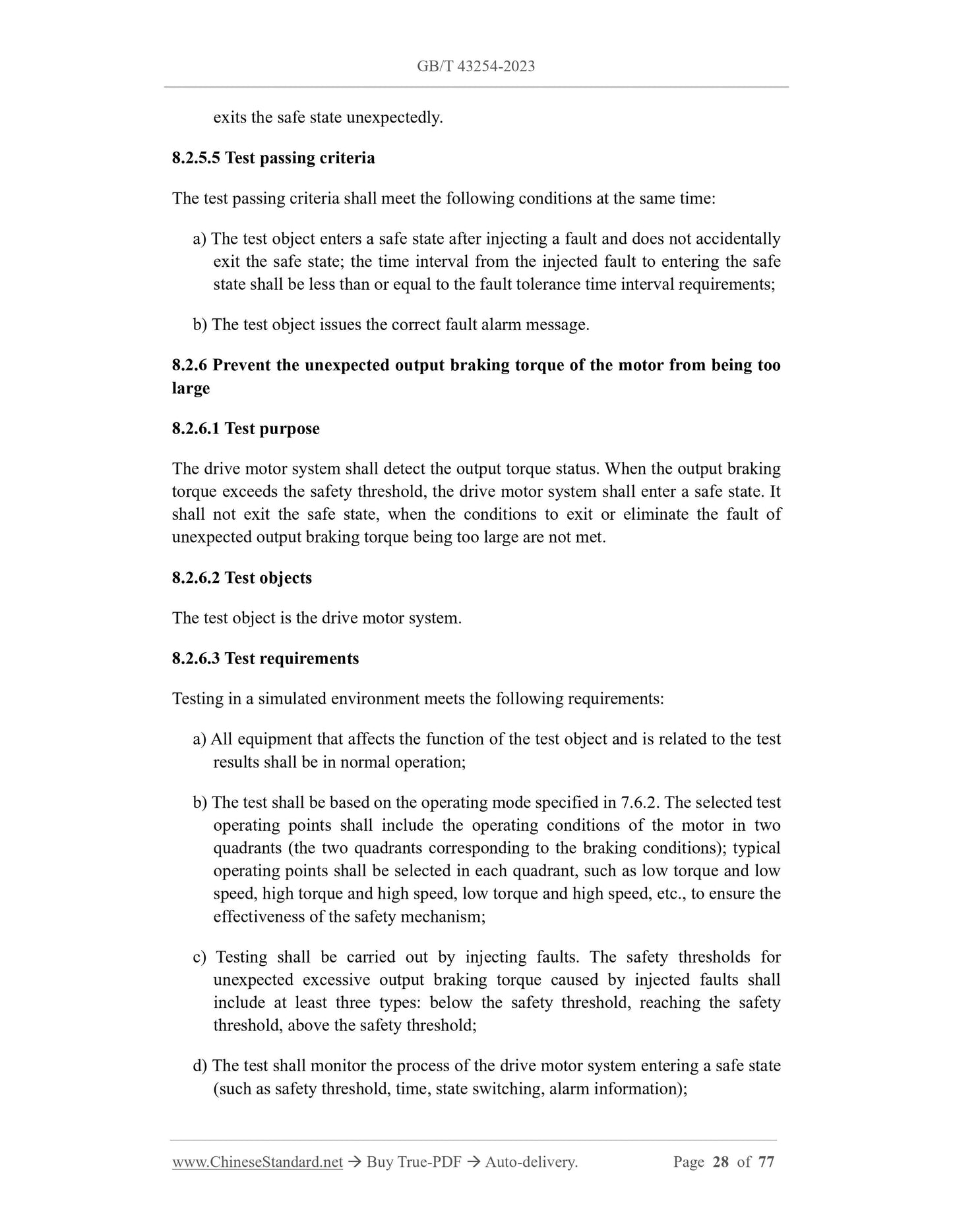
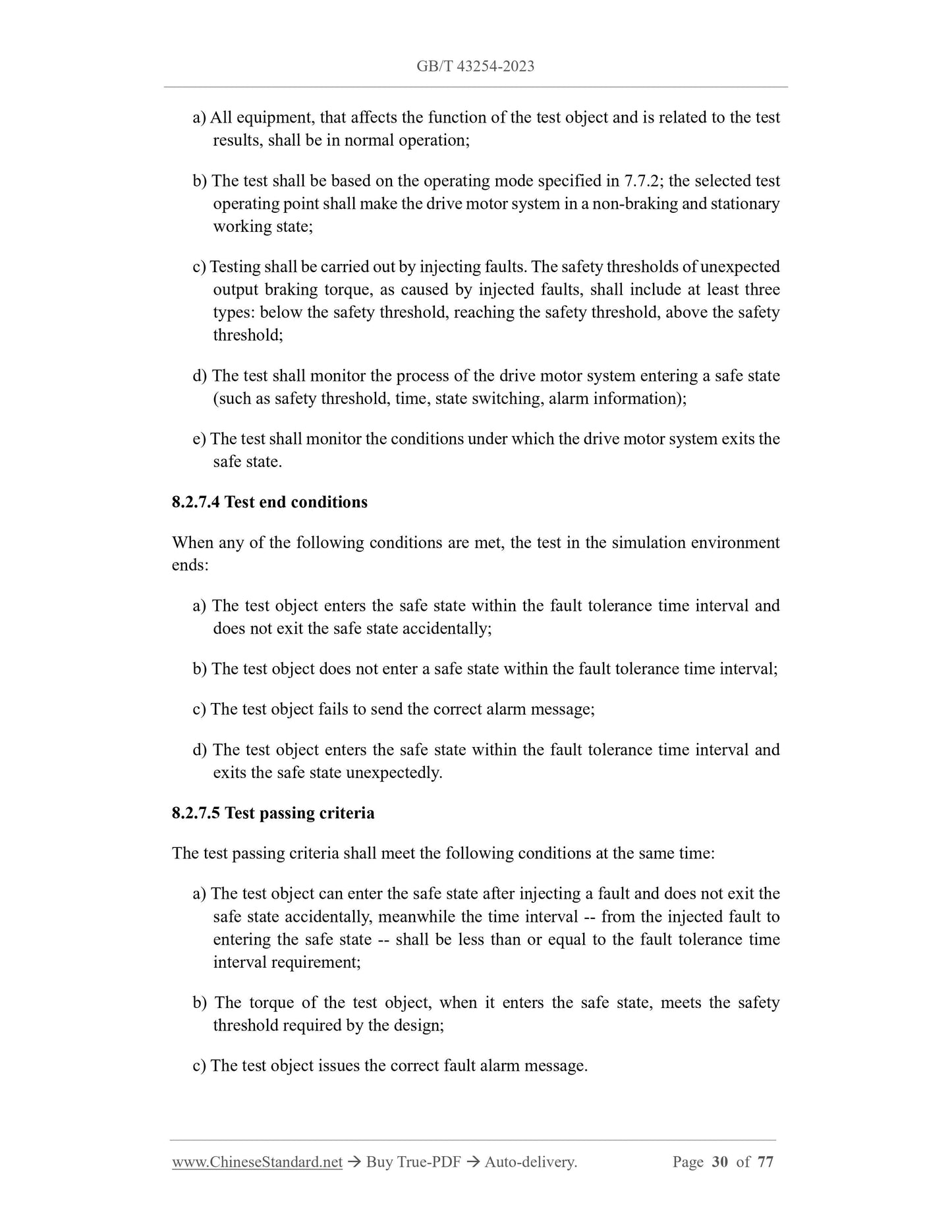
1
/
of
12
www.ChineseStandard.us -- Field Test Asia Pte. Ltd.
GB/T 43254-2023 English PDF (GB/T43254-2023)
Regular price
$860.00
Regular price
Sale price
$860.00
Unit price
/
per
Shipping calculated at checkout.
Couldn't load pickup availability
GB/T 43254-2023: Functional safety requirements and testing methods for drive motor system of electric vehicles
Delivery: 9 seconds. Download (& Email) true-PDF + Invoice.
Get Quotation: Click GB/T 43254-2023 (Self-service in 1-minute)
Historical versions (Master-website): GB/T 43254-2023
Preview True-PDF (Reload/Scroll-down if blank)
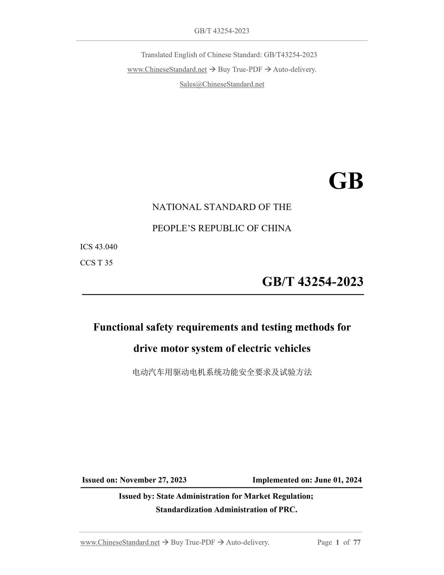
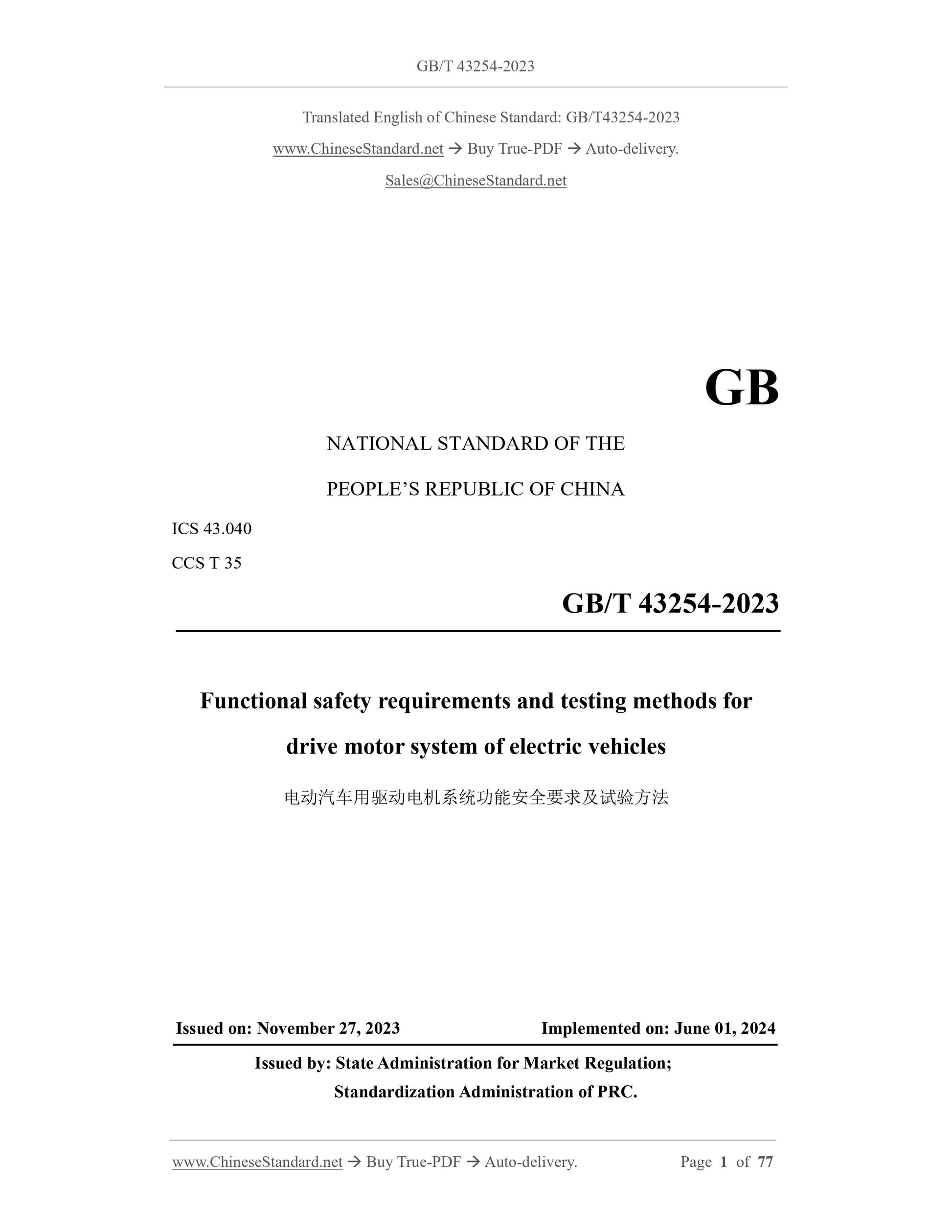
GB/T 43254-2023
GB
NATIONAL STANDARD OF THE
PEOPLE’S REPUBLIC OF CHINA
ICS 43.040
CCS T 35
Functional safety requirements and testing methods for
drive motor system of electric vehicles
ISSUED ON: NOVEMBER 27, 2023
IMPLEMENTED ON: JUNE 01, 2024
Issued by: State Administration for Market Regulation;
Standardization Administration of PRC.
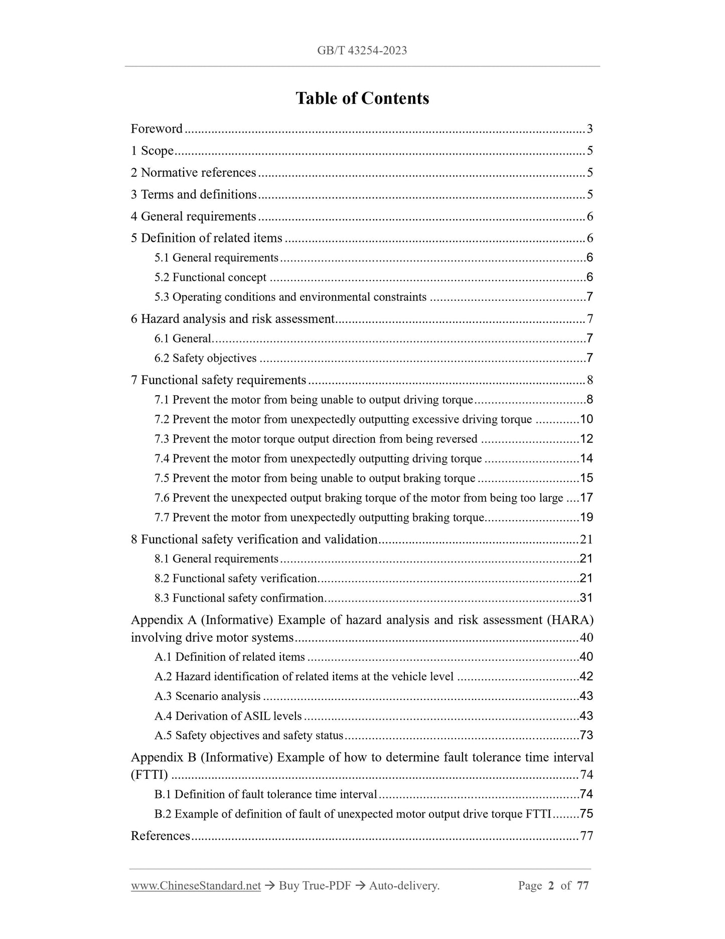
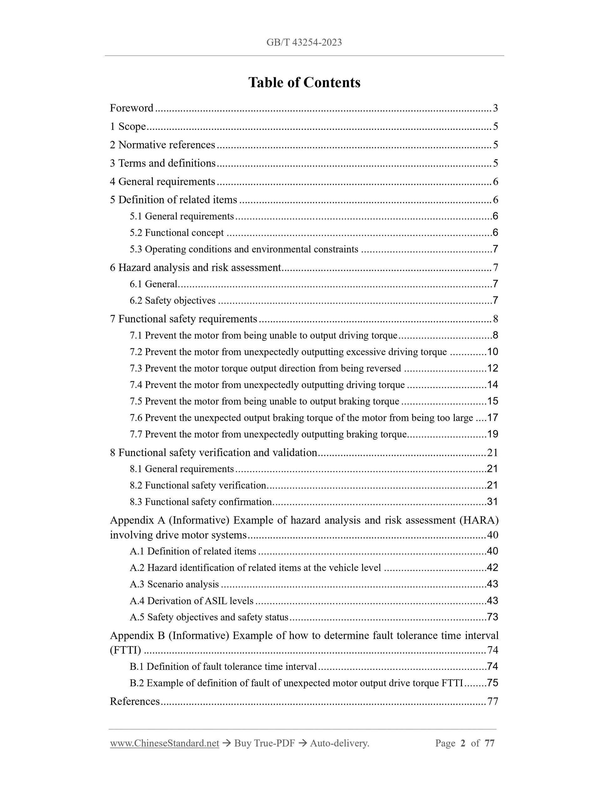
Table of Contents
Foreword ... 3
1 Scope ... 5
2 Normative references ... 5
3 Terms and definitions ... 5
4 General requirements ... 6
5 Definition of related items ... 6
5.1 General requirements ... 6
5.2 Functional concept ... 6
5.3 Operating conditions and environmental constraints ... 7
6 Hazard analysis and risk assessment ... 7
6.1 General... 7
6.2 Safety objectives ... 7
7 Functional safety requirements ... 8
7.1 Prevent the motor from being unable to output driving torque ... 8
7.2 Prevent the motor from unexpectedly outputting excessive driving torque ... 10
7.3 Prevent the motor torque output direction from being reversed ... 12
7.4 Prevent the motor from unexpectedly outputting driving torque ... 14
7.5 Prevent the motor from being unable to output braking torque ... 15
7.6 Prevent the unexpected output braking torque of the motor from being too large ... 17
7.7 Prevent the motor from unexpectedly outputting braking torque ... 19
8 Functional safety verification and validation ... 21
8.1 General requirements ... 21
8.2 Functional safety verification ... 21
8.3 Functional safety confirmation ... 31
Appendix A (Informative) Example of hazard analysis and risk assessment (HARA)
involving drive motor systems ... 40
A.1 Definition of related items ... 40
A.2 Hazard identification of related items at the vehicle level ... 42
A.3 Scenario analysis ... 43
A.4 Derivation of ASIL levels ... 43
A.5 Safety objectives and safety status ... 73
Appendix B (Informative) Example of how to determine fault tolerance time interval
(FTTI) ... 74
B.1 Definition of fault tolerance time interval ... 74
B.2 Example of definition of fault of unexpected motor output drive torque FTTI ... 75
References ... 77
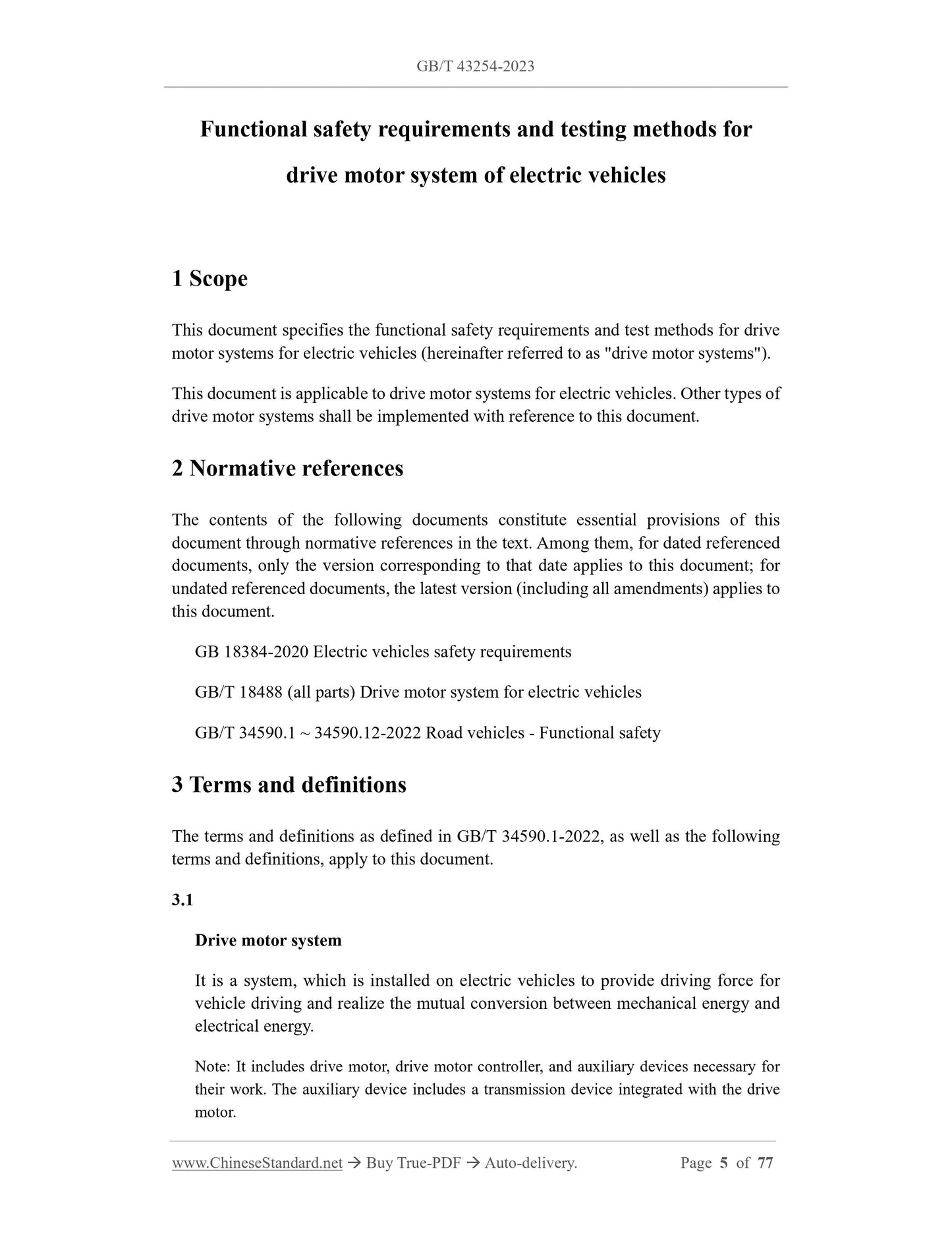
Functional safety requirements and testing methods for
drive motor system of electric vehicles
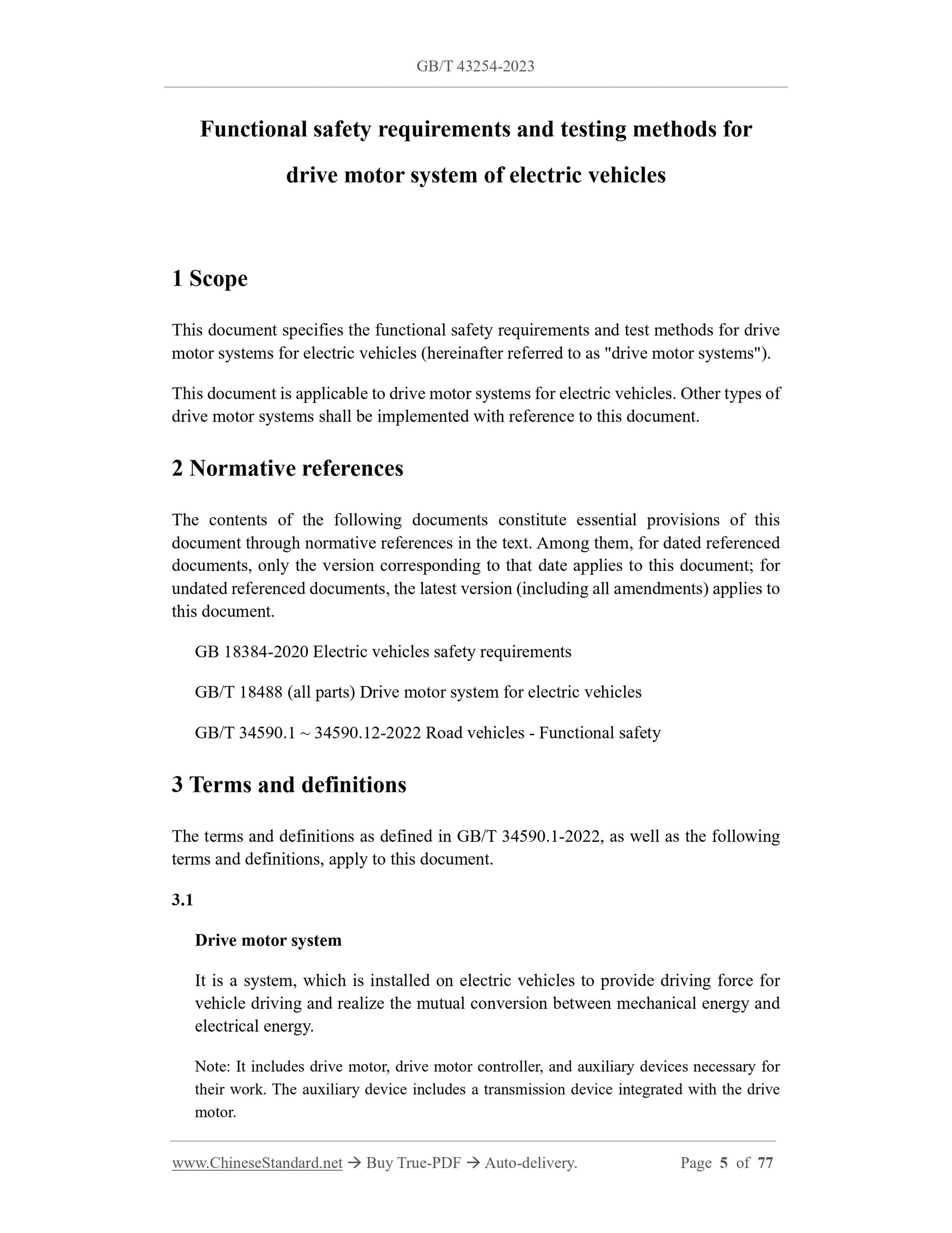
1 Scope
This document specifies the functional safety requirements and test methods for drive
motor systems for electric vehicles (hereinafter referred to as "drive motor systems").
This document is applicable to drive motor systems for electric vehicles. Other types of
drive motor systems shall be implemented with reference to this document.
2 Normative references
The contents of the following documents constitute essential provisions of this
document through normative references in the text. Among them, for dated referenced
documents, only the version corresponding to that date applies to this document; for
undated referenced documents, the latest version (including all amendments) applies to
this document.
GB 18384-2020 Electric vehicles safety requirements
GB/T 18488 (all parts) Drive motor system for electric vehicles
GB/T 34590.1 ~ 34590.12-2022 Road vehicles - Functional safety
3 Terms and definitions
The terms and definitions as defined in GB/T 34590.1-2022, as well as the following
terms and definitions, apply to this document.
3.1
Drive motor system
It is a system, which is installed on electric vehicles to provide driving force for
vehicle driving and realize the mutual conversion between mechanical energy and
electrical energy.
Note: It includes drive motor, drive motor controller, and auxiliary devices necessary for
their work. The auxiliary device includes a transmission device integrated with the drive
motor.
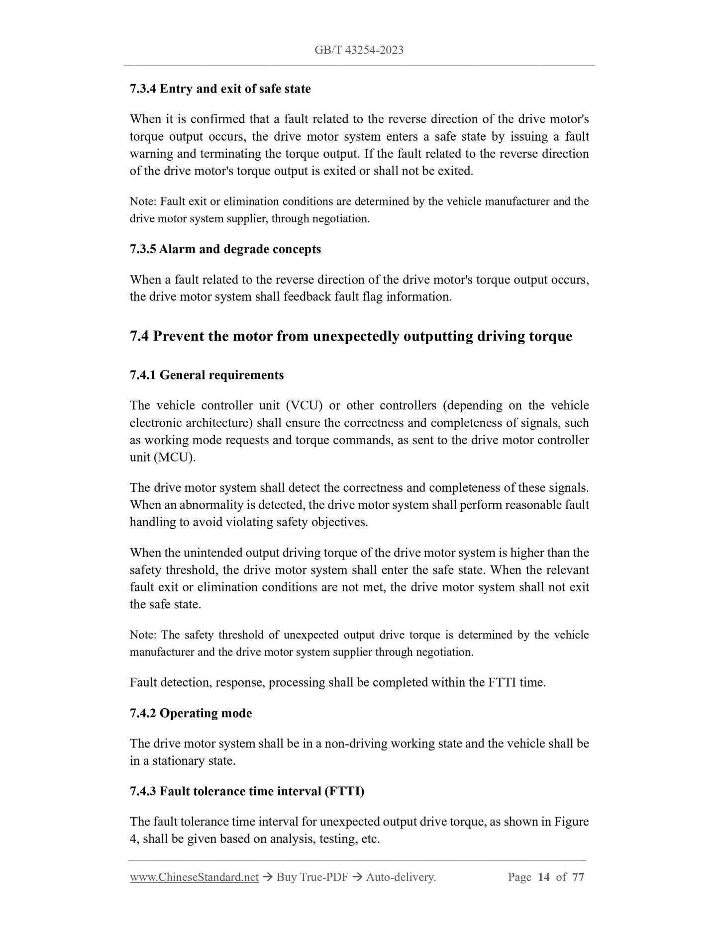
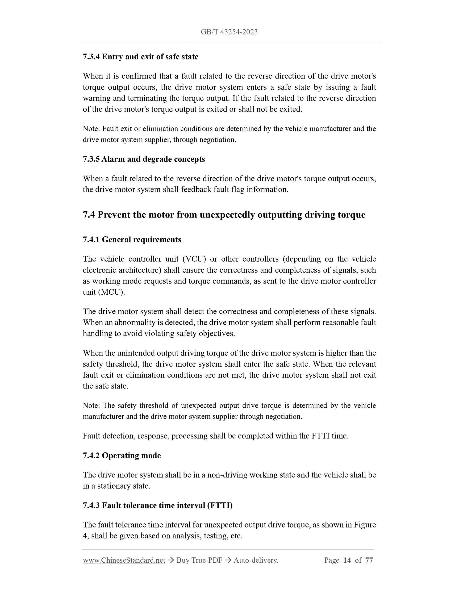
7.3.4 Entry and exit of safe state
When it is confirmed that a fault related to the reverse direction of the drive motor's
torque output occurs, the drive motor system enters a safe state by issuing a fault
warning and terminating the torque output. If the fault related to the reverse direction
of the drive motor's torque output is exited or shall not be exited.
Note: Fault exit or elimination conditions are determined by the vehicle manufacturer and the
drive motor system supplier, through negotiation.
7.3.5 Alarm and degrade concepts
When a fault related to the reverse direction of the drive motor's torque output occurs,
the drive motor system shall feedback fault flag information.
7.4 Prevent the motor from unexpectedly outputting driving torque
7.4.1 General requirements
The vehicle controller unit (VCU) or other controllers (depending on the vehicle
electronic architecture) shall ensure the correctness and completeness of signals, such
as working mode requests and torque commands, as sent to the drive motor controller
unit (MCU).
The drive motor system shall detect the correctness and completeness of these signals.
When an abnormality is detected, the drive motor system shall perform reasonable fault
handling to avoid violating safety objectives.
When the unintended output driving torque of the drive motor system is higher than the
safety threshold, the drive motor system shall enter the safe state. When the relevant
fault exit or elimination conditions are not met, the drive motor system shall not exit
the safe state.
Note: The safety threshold of unexpected output drive torque is determined by the vehicle
manufacturer and the drive motor system supplier through negotiation.
Fault detection, response, processing shall be completed within the FTTI time.
7.4.2 Operating mode
The drive motor system shall be in a non-driving working state and the vehicle shall be
in a stationary state.
7.4.3 Fault tolerance time interval (FTTI)
The fault tolerance time interval for unexpected output drive torque, as shown in Figure
4, shall be given based on analysis, testing, etc.
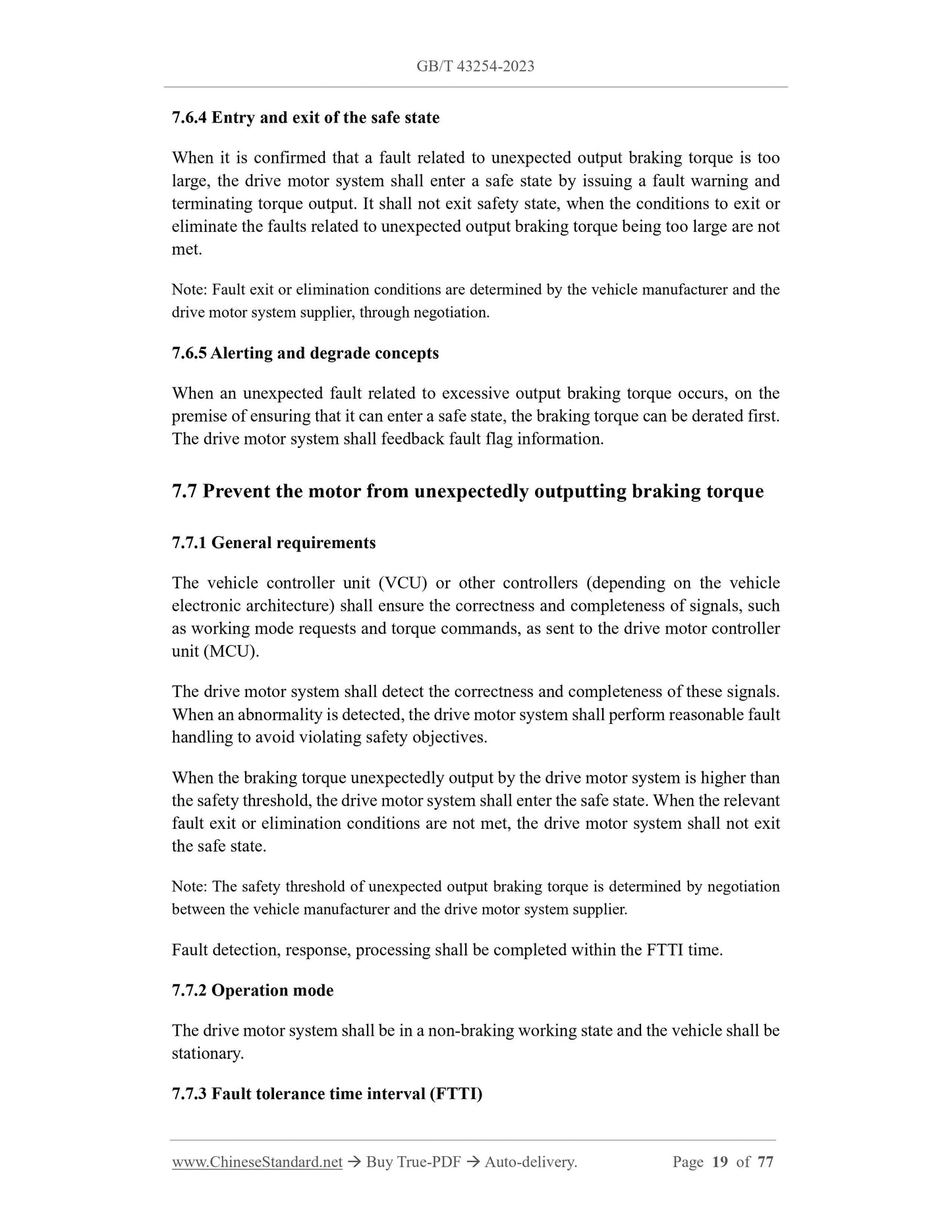
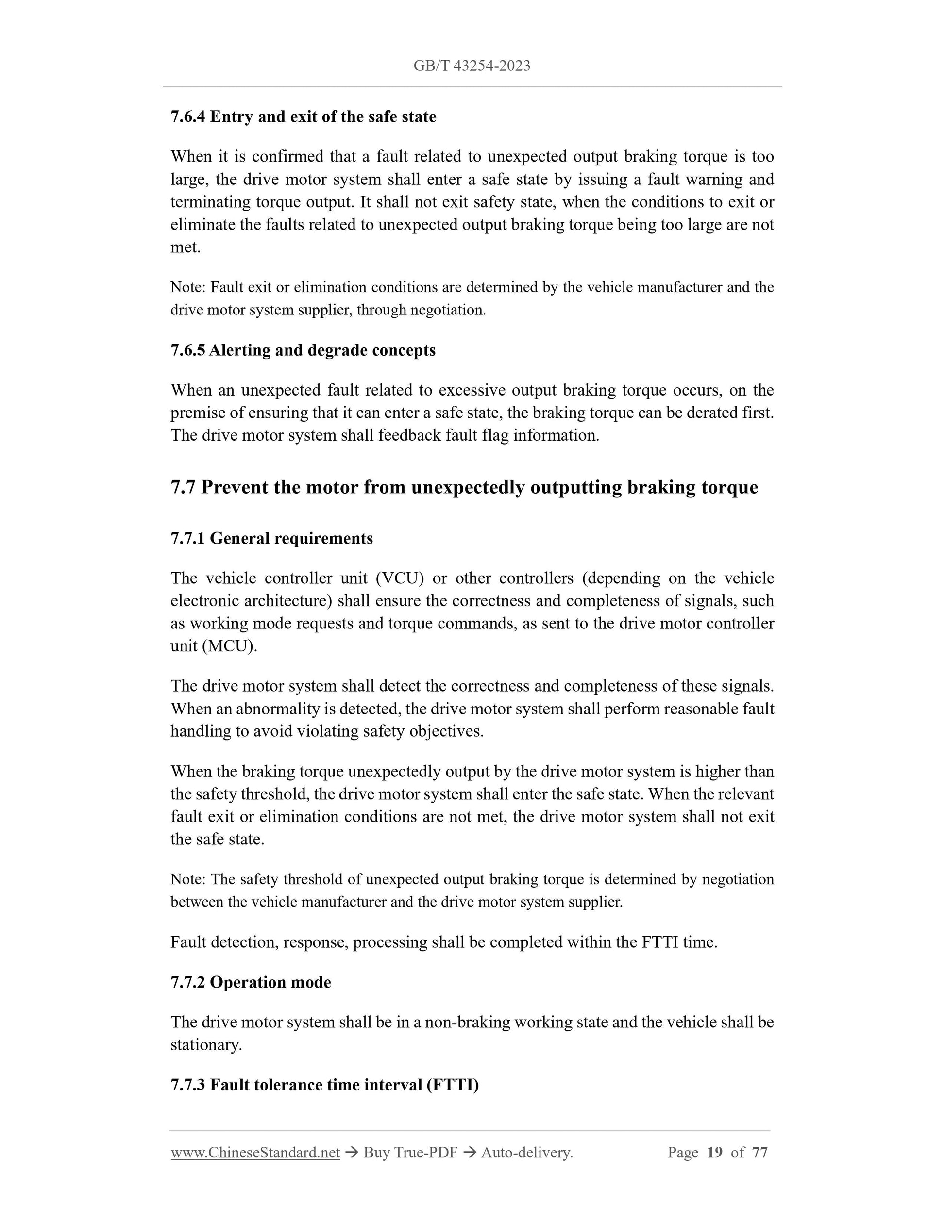
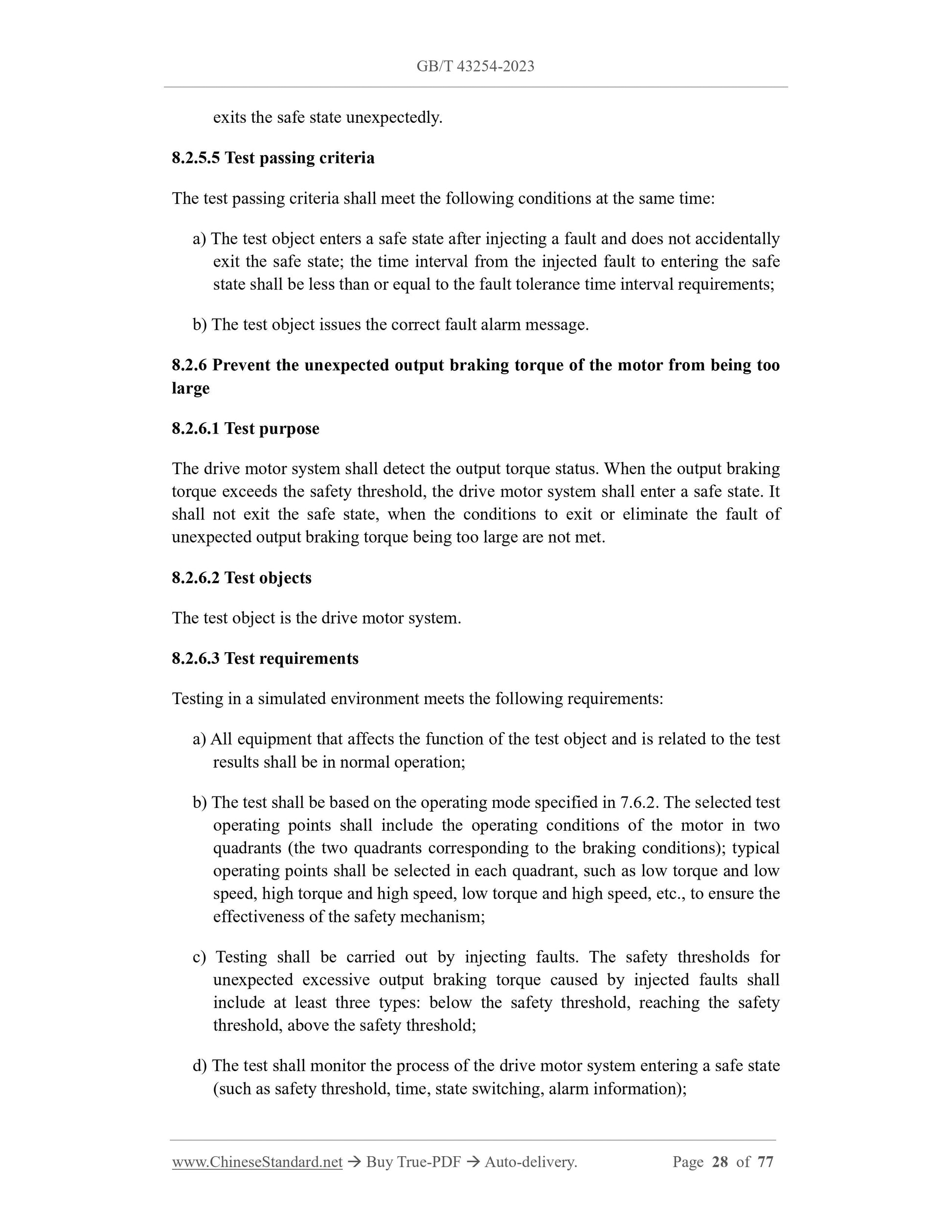
7.6.4 Entry and exit of the safe state
When it is confirmed that a fault related to unexpected output braking torque is too
large, the drive motor system shall enter a safe state by issuing a fault warning and
terminating torque output. It shall not exit safety state, when the conditions to exit or
eliminate the faults related to unexpected output braking torque being too large are not
met.
Note: Fault exit or elimination conditions are determined by the vehicle manufacturer and the
drive motor system supplier, through negotiation.
7.6.5 Alerting and degrade concepts
When an unexpected fault related to excessive output braking torque occurs, on the
premise of ensuring that it can enter a safe state, the braking torque can be derated first.
The drive motor system shall feedback fault flag information.
7.7 Prevent the motor from unexpectedly outputting braking torque
7.7.1 General requirements
The vehicle controller unit (VCU) or other controllers (depending on the vehicle
electronic architecture) shall ensure the correctness and completeness of signals, such
as working mode requests and torque commands, as sent to the drive motor controller
unit (MCU).
The drive motor system shall detect the correctness and completeness of these signals.
When an abnormality is detected, the drive motor system shall perform reasonable fault
handling to avoid violating safety objectives.
When the braking torque unexpectedly output by the drive motor system is higher than
the safety threshold, the drive motor system shall enter the safe state. When the relevant
fault exit or elimination conditions are not met, the drive motor system shall not exit
the safe state.
Note: The safety threshold of unexpected output braking torque is determined by negotiation
between the vehicle manufacturer and the drive motor system supplier.
Fault detection, response, processing shall be completed within the FTTI time.
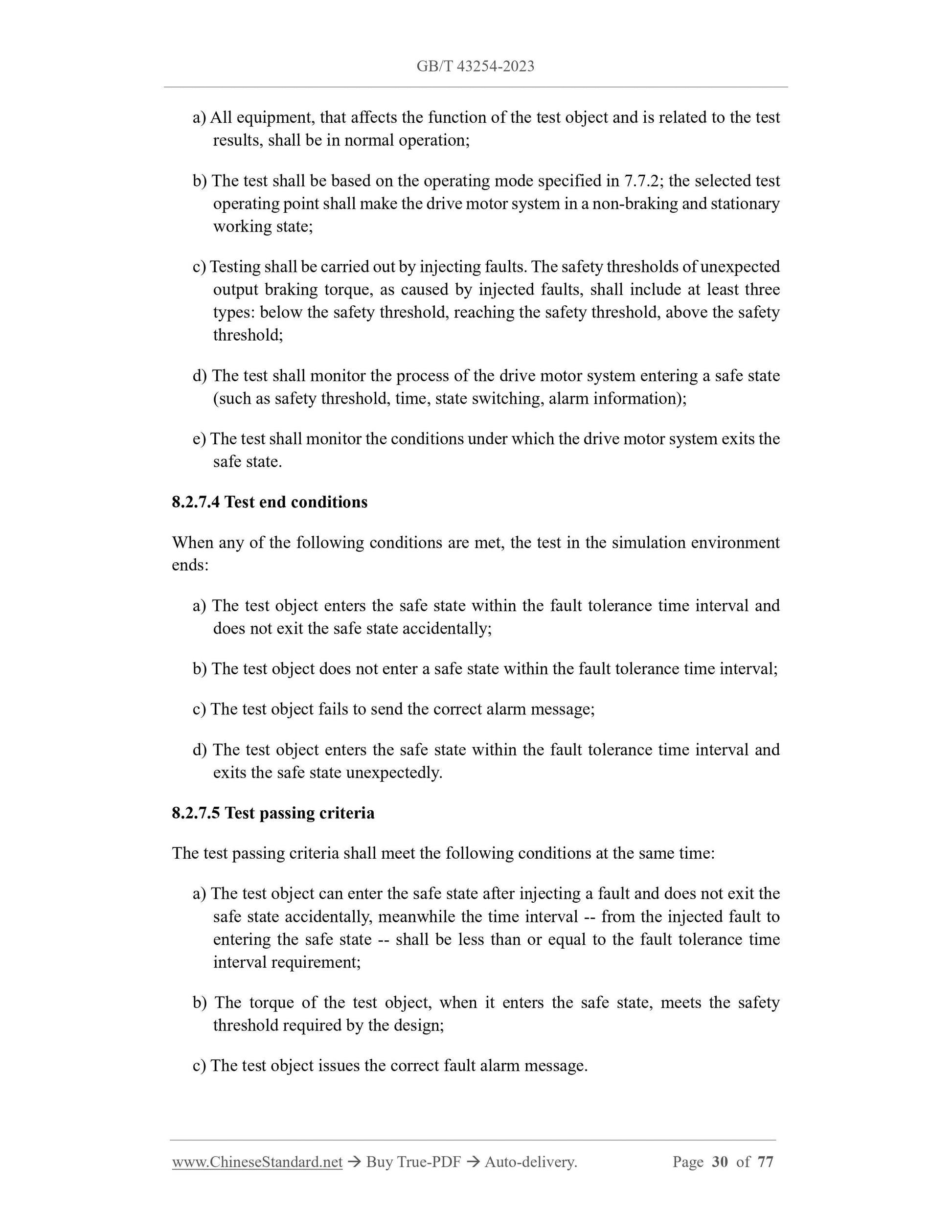
7.7.2 Operation mode
The drive motor system shall be in a non-braking working state and the vehicle shall be
stationary.
7.7.3 Fault tolerance time interval (FTTI)
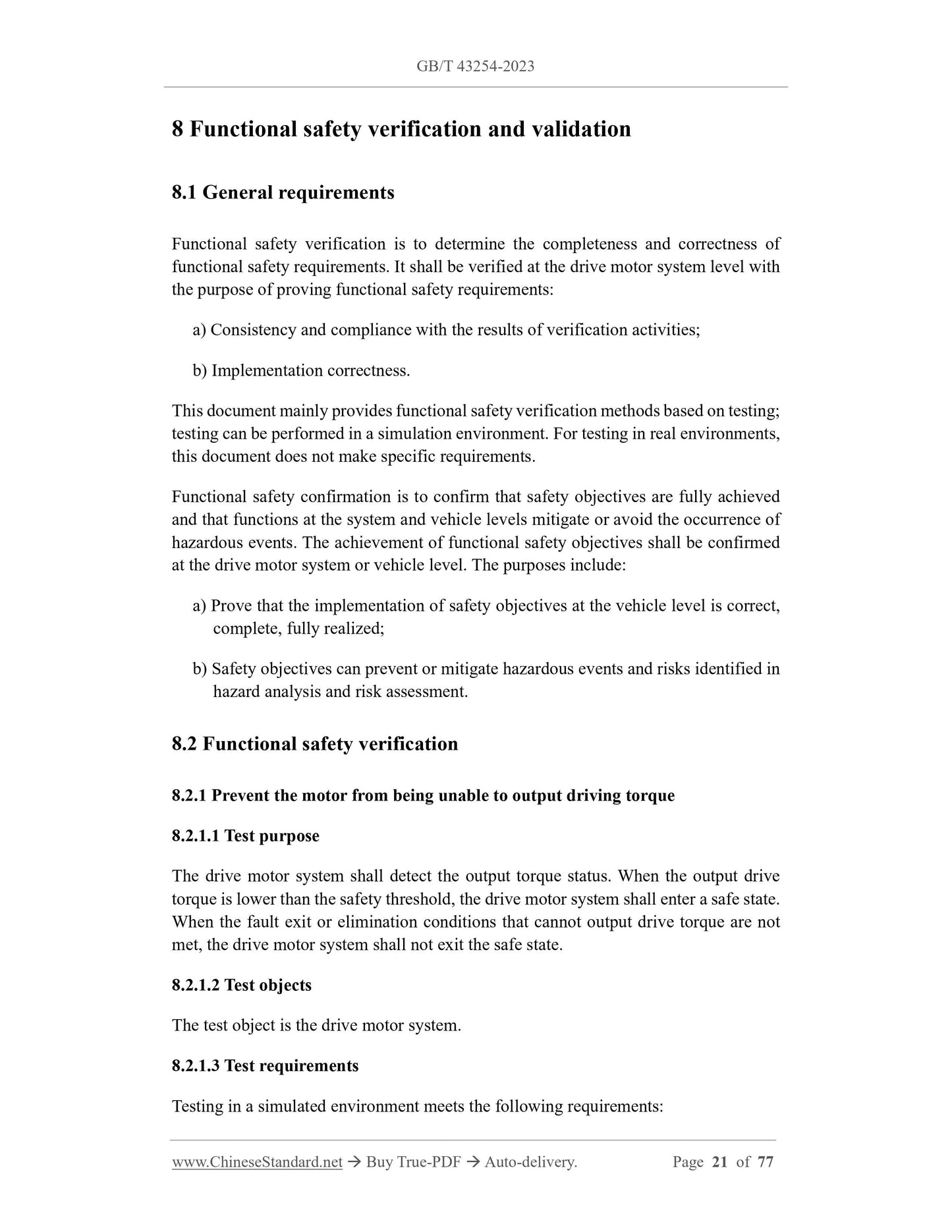
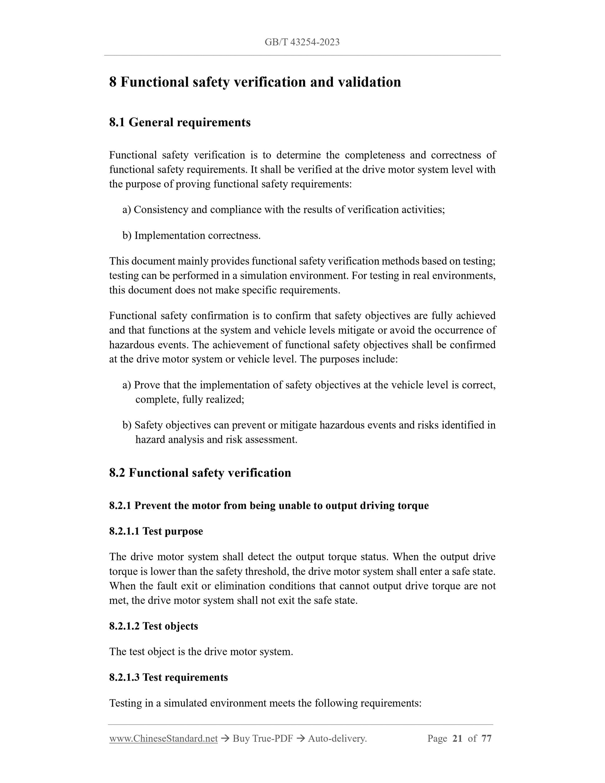
8 Functional safety verification and validation
8.1 General requirements
Functional safety verification is to determine the completeness and correctness of
functional safety requirements. It shall be verified at the drive motor system level with
the purpose of proving functional safety requirements:
a) Consistency and compliance with the results of verification activities;
b) Implementation correctness.
This document mainly provides functional safety verification methods based on testing;
testing can be performed in a simulation environment. For testing in real environments,
this document does not make specific requirements.
Functional safety confirmation is to confirm that safety objectives are fully achieved
and that functions at the system and vehicle levels mitigate or avoid the occurrence of
hazardous events. The achievement of functional safety objectives shall be confirmed
at the drive motor system or vehicle level. The purposes include:
a) Prove that the implementation of safety objectives at the vehicle level is correct,
complete, fully realized;
b) Safety objectives can prevent or mitigate hazardous events and risks identified in
hazard analysis and risk assessment.
8.2 Functional safety verification
8.2.1 Prevent the motor from being unable to output driving torque
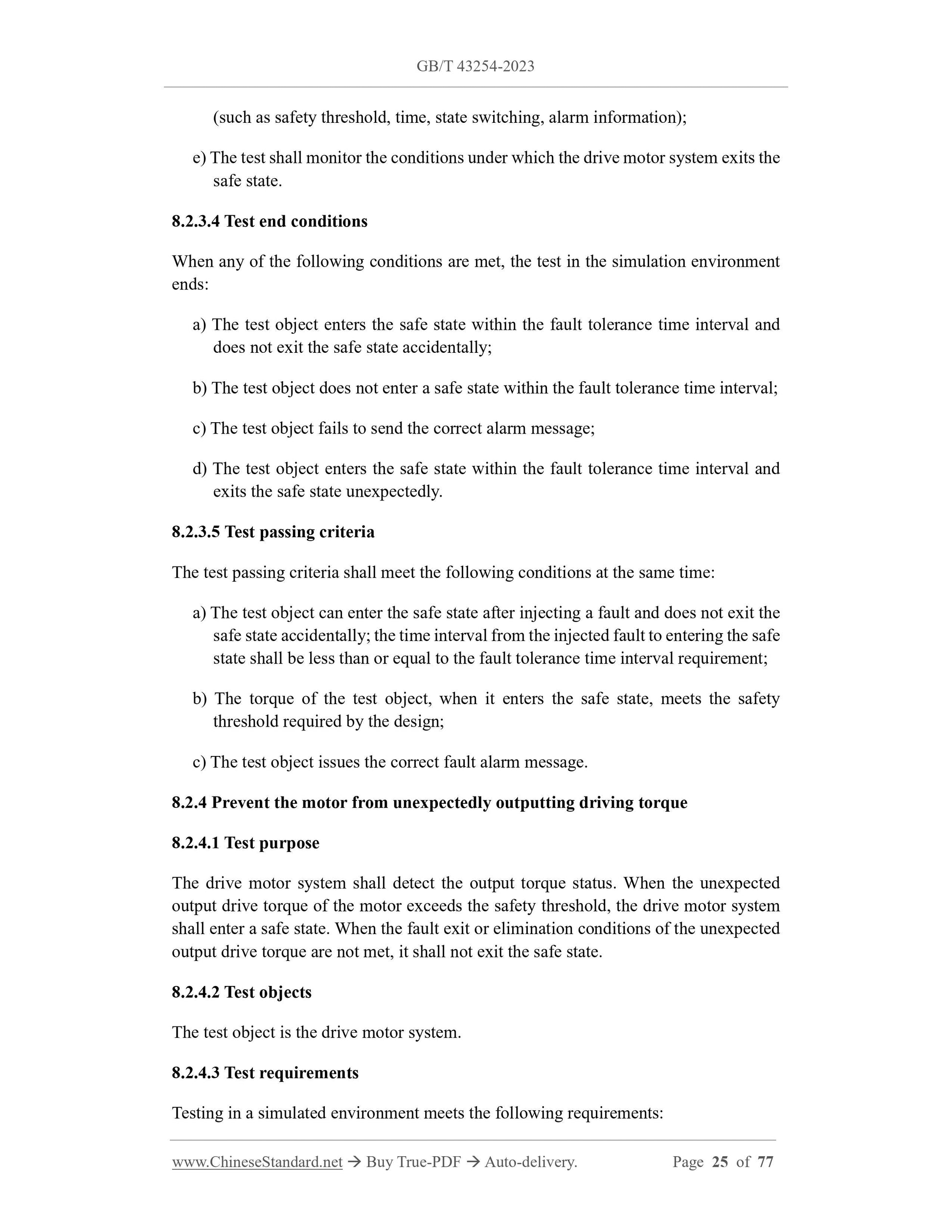
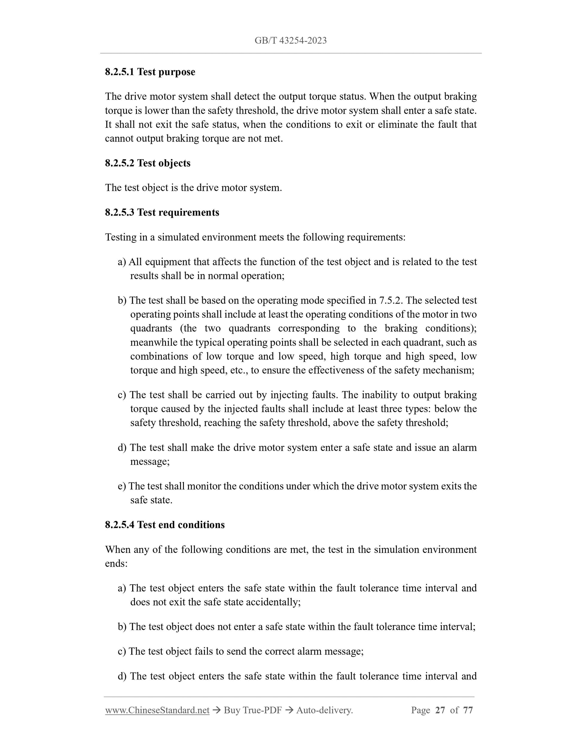
8.2.1.1 Test purpose
The drive motor system shall detect the output torque status. When the output drive
torque is lower than the safety threshold, the drive motor system shall enter a safe state.
When the fault exit or elimination conditions that cannot output drive torque are not
met, the drive motor system shall not exit the safe state.
8.2.1.2 Test objects
The test object is the drive motor system.
8.2.1.3 Test requirements
Testing in a simulated environment meets the following requirements:
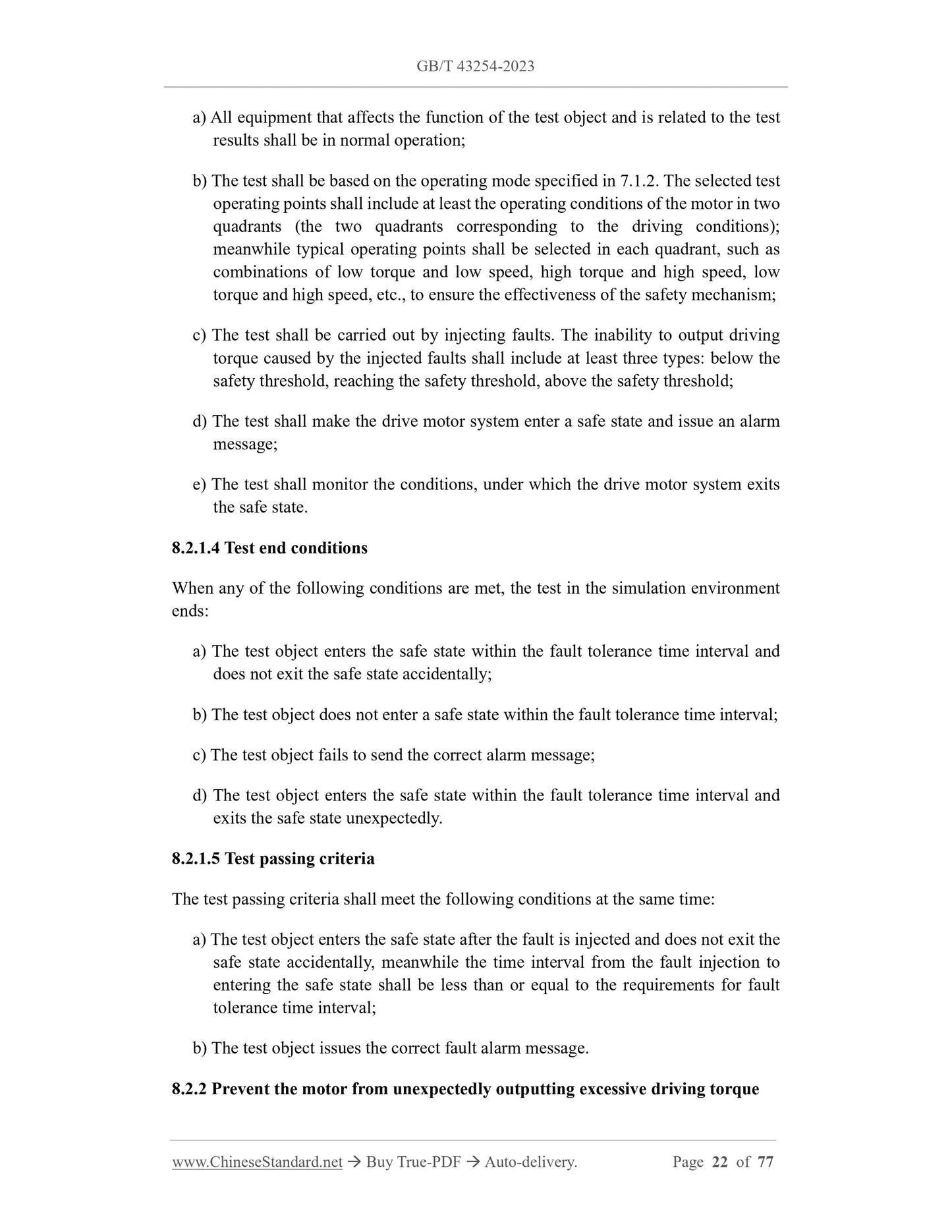
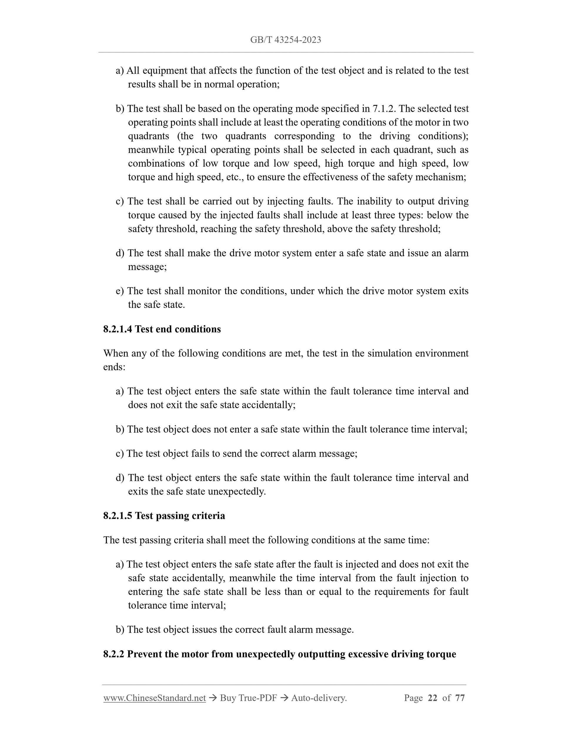
a) All equipment that affects the function of the test object and is related to the test
results shall be in normal operation;
b) The test shall be based on the operating mode specified in 7.1.2. The selected test
operating points shall include at least the operating conditions of the motor in two
quadrants (the two quadrants corresponding to the driving conditions);
meanwhile typical operating points shall be selected in each quadrant, such as
combinations of low torque and low speed, high torque and high speed, low
torque and high speed, etc., to ensure the effectiveness of the safety mechanism;
c) The test shall be carried out by injecting faults. The inability to output driving
torque caused by the injected faults shall include at least three types: below the
safety threshold, reaching the safety threshold, above the safety threshold;
d) The test shall make the drive motor system enter a safe state and issue an alarm
message;
e) The test shall monitor the conditions, under which the drive motor system exits
the safe state.
8.2.1.4 Test end conditions
When any of the following conditions are met, the test in the simulation environment
ends:
a) The test object enters the safe state within the fault tolerance time interval and
does not exit the safe state accidentally;
b) The test object does not enter a safe state within the fault tolerance time interval;
c) The test object fails to send the correct alarm message;
d) The test object enters the safe state within the fault tolerance time interval and
exits the safe state unexpectedly.
8.2.1.5 Test passing criteria
The test passing criteria shall meet the following conditions at the same time:
a) The test object enters the safe state after the fault is injected and does not exit the
safe state accidentally, meanwhile the time interval from the fault injection to
entering the safe state shall be less than or equal to the requirements for fault
tolerance time interval;
b) The test object issues the correct fault alarm message.
8.2.2 Prevent the motor from unexpectedly outputting excessive driving torque
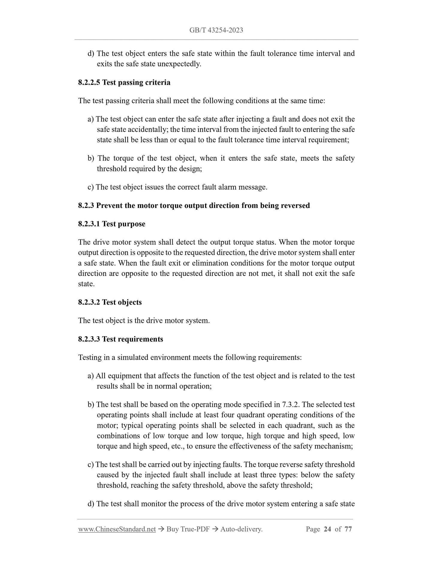
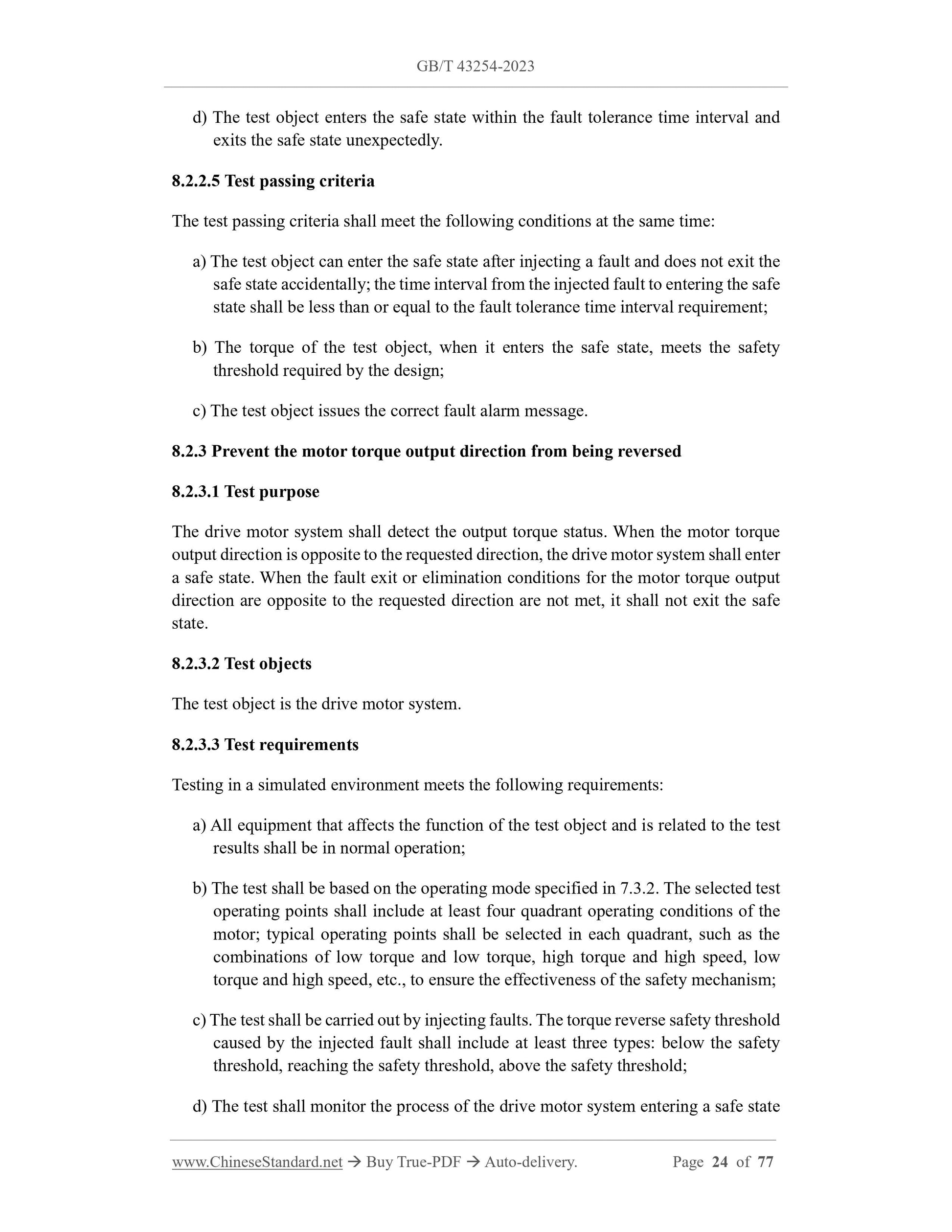
d) The test object enters the safe state within the fault tolerance time interval and
exits the safe state unexpectedly.
8.2.2.5 Test passing criteria
The test passing criteria shall meet the following conditions at the same time:
a) The test object can enter the safe state after injecting a fault and does not exit the
safe state accidentally; the time interval from the injected fault to entering the safe
state shall be less than or equal to the fault tolerance time interval requirement;
b) The torque of the test object, when it enters the safe state, meets the safety
threshold required by the design;
c) The test object issues the correct fault alarm message.
8.2.3 Prevent the motor torque output direction from being reversed
8.2.3.1 Test purpose
The drive motor system shall detect the output torque status. When the motor torque
output direction is opposite to the requested direction, the drive motor system shall enter
a safe state. When the fault exit or elimination conditions for the motor torque output
direction are opposite to the requested direction are not met, it shall not exit the safe
state.
8.2.3.2 Test objects
The test object is the drive motor system.
8.2.3.3 Test requirements
Testing in a simulated environment meets the following requirements:
a) All equipment that affects the function of the test object and is related to the test
results shall be in normal operation;
b) The test shall be based on the operating mode specified in 7.3.2. The selected test
operating points shall include at least four quadrant operating conditions of the
motor; typical operating points shall be selected in each quadrant, such as the
combinations of low torque and low torque, high torque and high speed, low
torque and high speed, etc., to ensure the effectiveness of the safety mechanism;
c) The test shall be carried out by injecting faults. The torque reverse safety threshold
caused by the injected fault shall include at least three types: below the safety
threshold, reaching the safety threshold, above the safety threshold;
d) The test shall monitor the process of the drive motor system entering a safe state
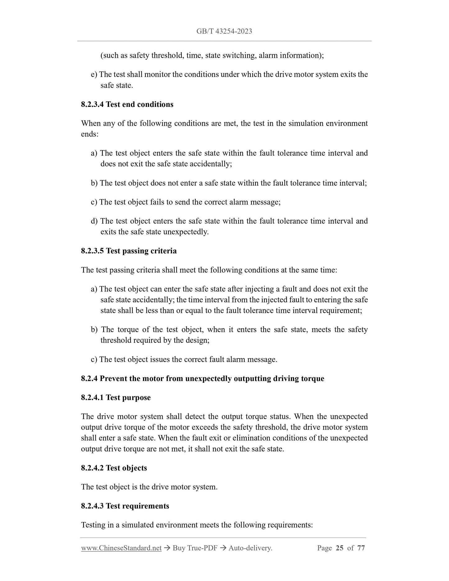
(such as safety threshold, t...
Share