Skip to product information
1 of 10

PayPal, credit cards. Download editable-PDF & invoice in 1 second!

GB/T 42517.2-2023 English PDF (GB/T42517.2-2023)

GB/T 42517.2-2023 English PDF (GB/T42517.2-2023)

Regular price $755.00 USD
Regular price Sale price $755.00 USD
Sale Sold out
Shipping calculated at checkout.
Delivery: 3 seconds. Download true-PDF + Invoice.
Get Quotation: Click GB/T 42517.2-2023 (Self-service in 1-minute)
Historical versions (Master-website): GB/T 42517.2-2023
Preview True-PDF (Reload/Scroll-down if blank)

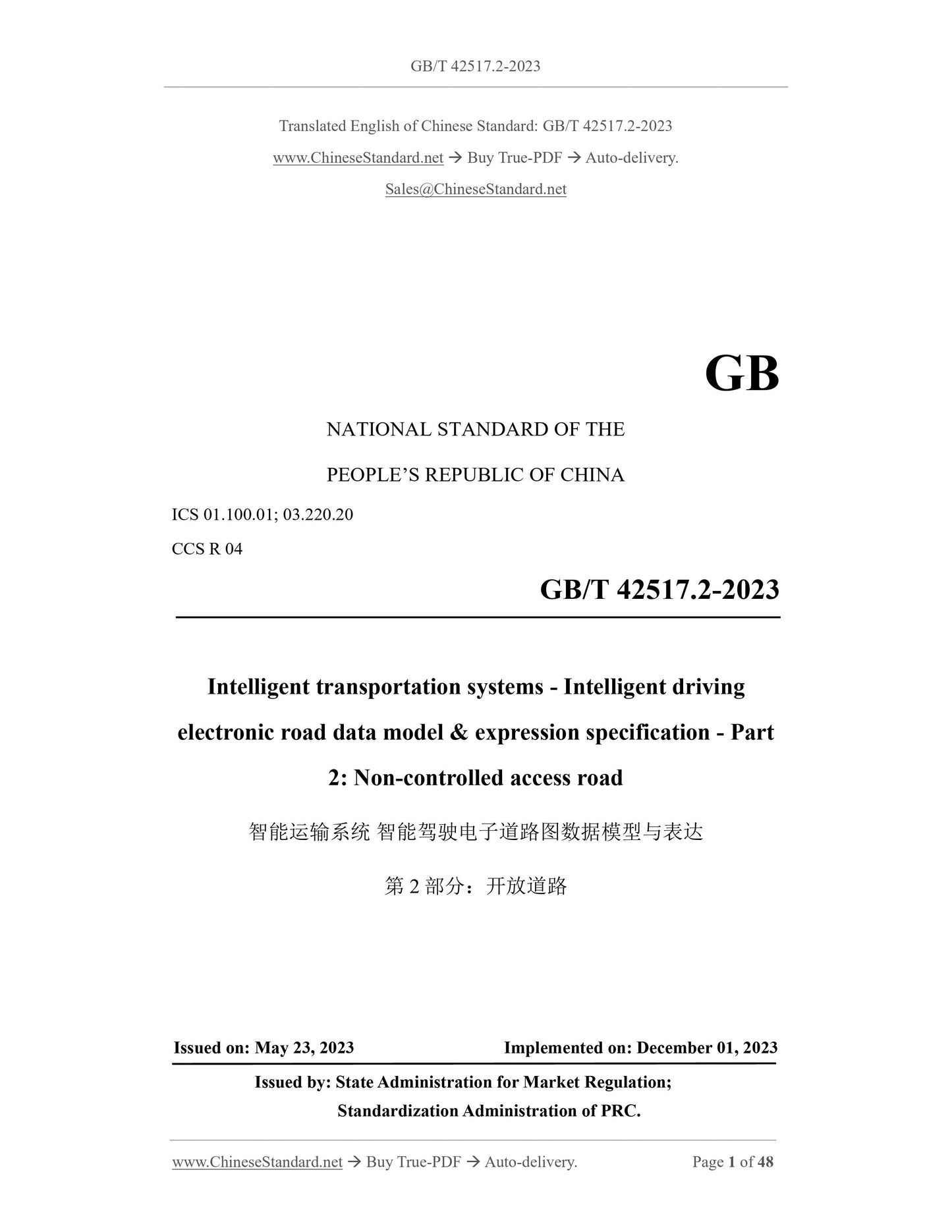
GB/T 42517.2-2023: Intelligent transportation systems - Intelligent driving electronic road data model and expression specification - Part 2: Non-controlled access road
GB/T 42517:2-2023
ICS01:100:01;03:220:20
CCSR04
National Standards of People's Republic of China
Intelligent Transportation System
Intelligent driving electronic road map data model and expression
Part 2: Open Road
Released on 2023-05-23
2023-12-01 Implementation
State Administration for Market Regulation
Released by the National Standardization Management Committee
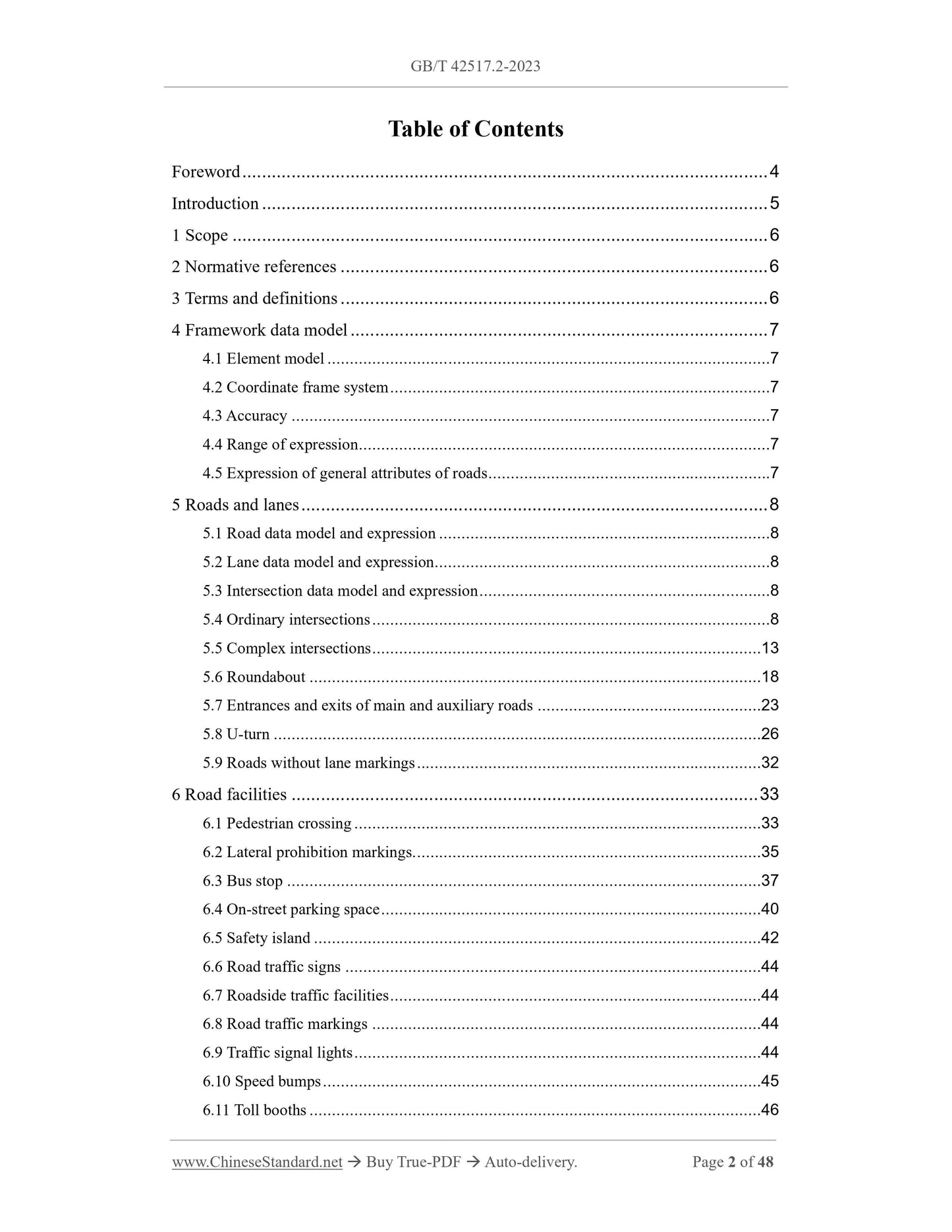
table of contents
Preface V
Introduction VI
1 Range 1
2 Normative references 1
3 Terms and Definitions 1
4 Framework data model 1
4:1 Element model 1
4:2 Coordinate frame system 1
4:3 Accuracy 1
4:4 Range of expression 2
4:5 General attribute expression of road 2
5 Roads and lanes 2
5:1 Road data model and expression 2
5:2 Lane data model and expression 2
5:3 Intersection data model and expression 2
5:4 Ordinary intersection 2
5:5 Complex intersection 6
5:6 Roundabout 11
5:7 Main and auxiliary road entrances and exits 16
5:8 U-turn port 19
5:9 Roads without lane markings 25
6 Road facilities 26
6:1 Crosswalks 26
6:2 Horizontal prohibited marking lines 28
6:3 Bus station 30
6:4 On-street parking 32
6:5 Safety islands 34
6:6 Road traffic signs 35
6:7 Roadside traffic facilities 35
6:8 Road traffic markings 36
6:9 Traffic lights 36
6:10 Speed bumps 37
6:11 Toll booths 37
6:12 Checkpoints 37
6:13 Obstacles above 37
6:14 Roadside structures 37
6:15 Rods 37
6:16 Gantry 37
6:17 Tunnels 37
6:18 Roadside monitoring and communication equipment 37
Reference 38
Figure 1 Normal intersection scene Figure 2
Fig: 2 Schematic diagram of topological connection of virtual road reference line at common intersection 3
Figure 3 Simplified connection diagram of ordinary intersection lanes 4
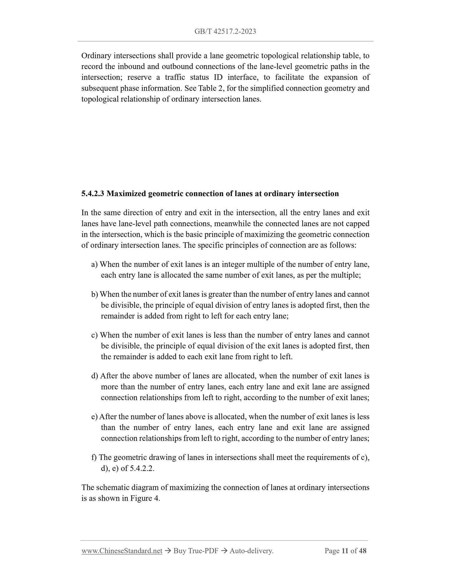
Figure 4 Schematic diagram of lane maximization connection at common intersections 5
Figure 5 Complicated intersection scene Figure 7
Figure 6 Schematic diagram of topological connection of virtual road reference line at complex intersection 8
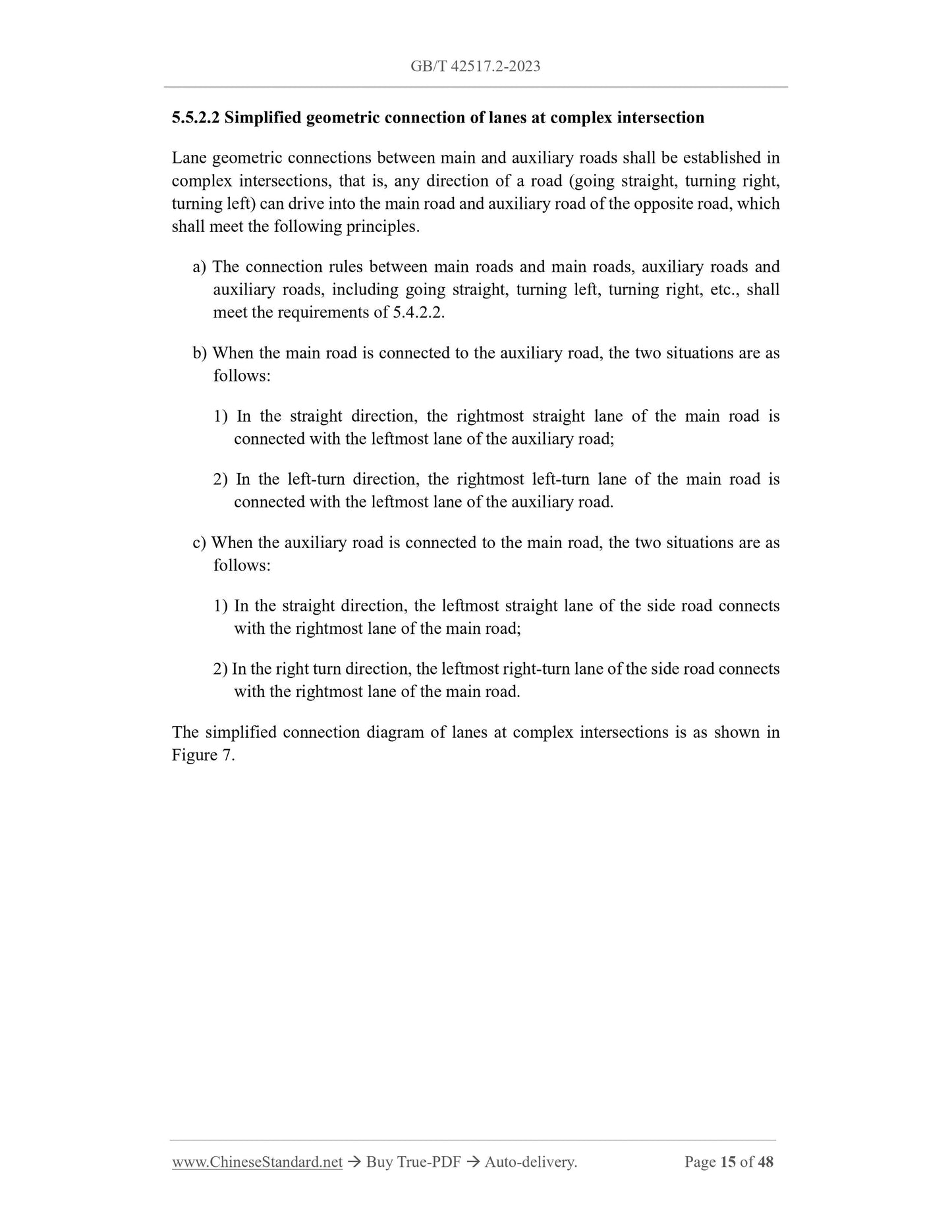
Figure 7 Schematic diagram of simplified connection of lanes at complex intersections9
Figure 8 Schematic diagram of lane maximization connection at complex intersections10
Figure 9 Roundabout scene Figure 12
Figure 10 Roundabout Figure 12
Fig: 11 Schematic diagram of topological connection of virtual road reference line at roundabout intersection 13
Figure 12 Schematic diagram of simplified connection of lanes at roundabout intersections 14
Figure 13 Schematic diagram of maximum connection of lanes at roundabout intersections 15
Figure 14 Schematic diagram of the geometric connection of one-way entrance and exit roads on main and auxiliary roads 17
Figure 15 Schematic diagram of the geometric connection of the two-way entrance and exit roads of the main and auxiliary roads18
Figure 16 Schematic diagram of lane connection at the entrance and exit of main and auxiliary roads 19
Figure 17 Schematic diagram of one-way U-turn road connection 20
Figure 18 Schematic diagram of road connections at two-way U-turns 21
Figure 19 Schematic diagram of simplified geometric connection of one-way U-turn lanes 22
Figure 20 Schematic diagram of maximized geometric connection of one-way U-turn lanes 23
Figure 21 Schematic diagram of simplified geometric connection of two-way U-turn lanes 24
Figure 22 Schematic diagram of maximum geometric connection of two-way U-turn lanes 25
Figure 23 Geometric representation of a two-way road without lane markings 26
Figure 24 Pedestrian crossing data model 26
Figure 25 Pedestrian crossing scene Figure 27
Figure 26 Geometric representation of pedestrian crossings 27
Figure 27 Data model of horizontal prohibition markings 28
Figure 28 Horizontal prohibited marking type 29
Figure 29 Geometric expression of horizontal prohibition markings 29
Figure 30 Bus station data model Figure 30
Figure 31 Linear docking station 31
Figure 32 Harbor-style docking station 31
Figure 33 Geometric representation of the bus station 31
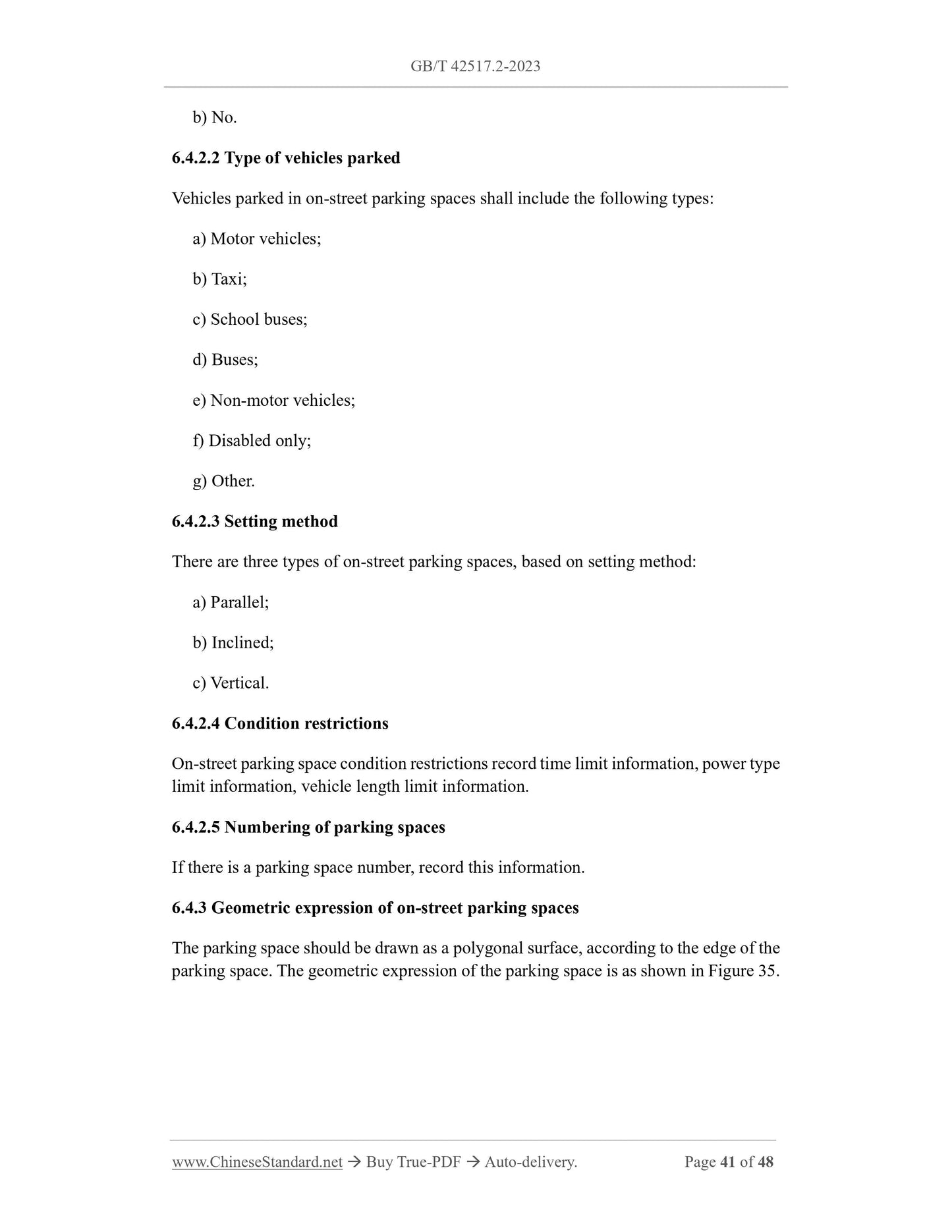
Figure 34 On-street parking space data model 32
Figure 35 Geometric expression of parking space 33
Figure 36 Safe Island Data Model 34
Figure 37 Geometric expression of safety island 35
Figure 38 Schematic diagram of the relationship between traffic lights and entering lanes 36
Table 1 Geometric and topological relationship of road connections at ordinary intersections Table 3
Table 2 Geometric and topological relations of simplified connection lanes at common intersections Table 4
Table 3 Geometric and topological relationship of lane maximization at common intersection Table 5
Table 4 Lane connection full relational topology of common intersection Table 6
Table 5 Geometric and topological relations of road connections at complex intersections Table 8
Table 6 Geometric and topological relationship of lane simplified connection at complex intersection Table 9
Table 7 Geometric and topological relationship of lane maximization at complex intersections Table 10
Table 8 Full-relational topology of lane connections at complex intersections Table 11
Table 9 Geometric and topological relationship of road connections at roundabouts Table 13
Table 10 Geometric and topological relations of simplified connection lanes at roundabout intersections Table 14
Table 11 Geometric and topological relationship of lane maximization at roundabout intersection Table 15
Table 12 Full-relational topology of lane connections at roundabouts Table 16
Table 13 Geometric and topological relationship of one-way entrances and exits of main and auxiliary roads Table 17
Table 14 Geometric and topological relationship of main and auxiliary road two-way traffic entrance and exit road connection Table 18
Table 15 Geometric and topological relationship of main and auxiliary road entrance and exit lane connections Table 19
Table 16 Geometric and topological relationship of one-way U-turn road connections Table 20
Table 17 Two-way U-turn Road Connection Geometric Topological Relationship Table 21
Table 18 One-way U-turn Lane Simplified Connection Geometric Topological Relationship Table 22
Table 19 Geometric and topological relationship of one-way U-turn lane maximization connection Table 23
Table 20 Two-way U-turn Lane Simplified Connection Geometric Topological Relationship Table 24
Table 21 Geometric and topological relations of maximum connection lanes at two-way U-turns Table 25
Table 22 Pedestrian crosswalk table structure 28
Table 23 Structure of Horizontal Prohibited Line Marking Table 30
Table 24 Bus stop table structure 32
Table 25 On-street parking space table structure 34
Table 26 Safety island table structure 35
Table 27 Correlation table between traffic lights at intersections and entering lanes 36
foreword
This document is in accordance with the provisions of GB/T 1:1-2020 "Guidelines for Standardization Work Part 1: Structure and Drafting Rules for Standardization Documents"
drafting:
This document is the second part of GB/T 42517 "Electronic Road Map Data Model and Expression for Intelligent Driving in Intelligent Transportation System":
GB/T 42517 has issued the following parts:
--- Part 1: Closed roads;
--- Part 2: Open road:
Please note that some contents of this document may refer to patents: The issuing agency of this document assumes no responsibility for identifying patents:
This document is proposed and managed by the National Intelligent Transportation System Standardization Technical Committee (SAC/TC268):
This document was drafted by: Beijing NavInfo Technology Co:, Ltd:, Zhongguancun China Communications International Intelligent Transportation Industry Alliance, Autonavi
Co:, Ltd:, Beijing Baidu Netcom Technology Co:, Ltd:, Highway Research Institute of the Ministry of Transport, Wuhan Zhonghaiting Data Technology Co:, Ltd:,
SAIC Motor Corporation Limited, Beijing University of Civil Engineering and Architecture:
The main drafters of this document: Zhu Dawei, Tian Ye, Gu Xiaofeng, Jiao Weiyun, Li Ru, Meng Decui, Luo Yuejun, Zeng Jia, Liu Lili, Wang Jian, Wang Chunhong,
Yin Wei, Bao Chen, Huang He, Yi Pengjun, Wang Miao, Guo Linxi, Wei Tao, Yu Pei, Lu Weina, Peng Wei, Zhang Mingang:
introduction
With the development of autonomous driving and vehicle-road collaboration technology, the electronic road map for intelligent driving is an important way to improve vehicle perception and promote vehicle-road information sharing:
Sharing and eliminating accident risks in blind spots provides road basic information guarantee: Data Model and Expression of Electronic Road Map Elements for Promoting Intelligent Driving
Standardization and standardization of design to improve the efficiency of road information sharing services, GB/T 42517 "Intelligent Transportation System Intelligent Driving Electronic Road
"Road Map Data Model and Expression" provides the requirements and methods for road data model and element expression, and is intended to be composed of two parts:
--- Part 1: Closed roads: The purpose is to specify the framework data model of closed roads, roads and
Data model and representation of lanes and road facilities:
--- Part 2: Open road: The purpose is to specify the framework data model, road and
Data model and representation of lanes and road facilities:
Intelligent Transportation System
Intelligent driving electronic road map data model and expression
Part 2: Open Road
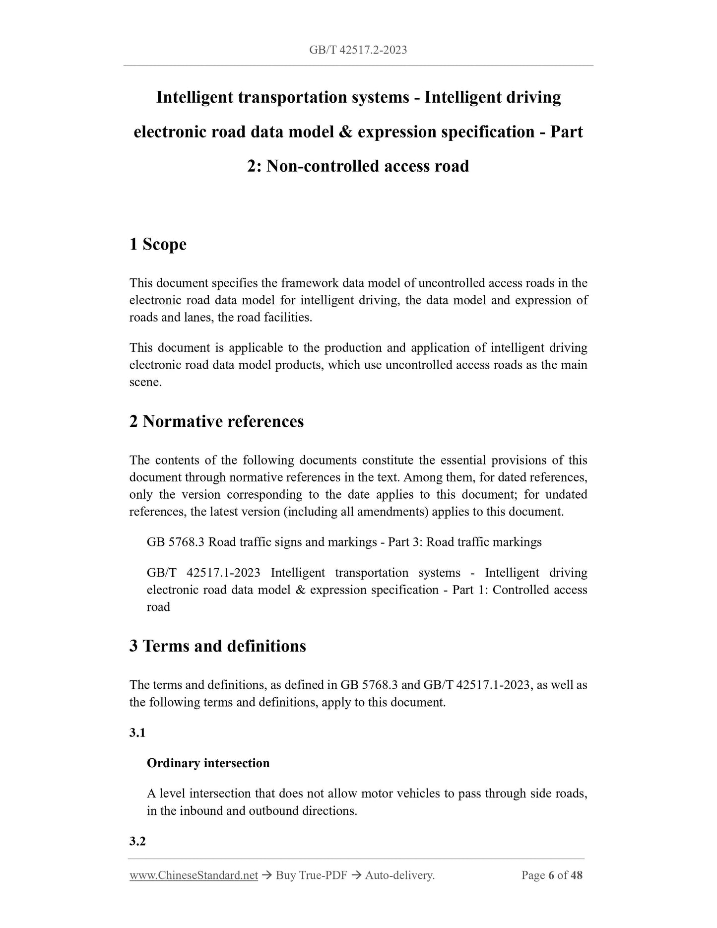
1 Scope
This document specifies the framework data model of open roads in the electronic road map for intelligent driving, the data of roads and lanes, and road facilities
Models and representations:
This document is applicable to the production and application of intelligent driving electronic road map products with open roads as the main scene:
2 Normative references
The contents of the following documents constitute the essential provisions of this document through normative references in the text: Among them, dated references
For documents, only the version corresponding to the date is applicable to this document; for undated reference documents, the latest version (including all amendments) is applicable to
this document:
GB 5768:3 Road traffic signs and markings Part 3: Road traffic markings
GB/T 42517:1-2023 Intelligent Transportation System Intelligent Driving Electronic Road Map Data Model and Expression Part 1: Closed
the way
3 Terms and Definitions
GB 5768:3, GB/T 42517:1-2023 and the following terms and definitions apply to this document:
3:1
Ordinary intersection ordinaryintersection
There are no at-grade intersections that allow motor vehicles to pass through side roads in the inbound and outbound directions:
3:2
complex intersection complexintersection
In at least one direction of entry or exit there is a level intersection that allows motor vehicles to pass through the side road:
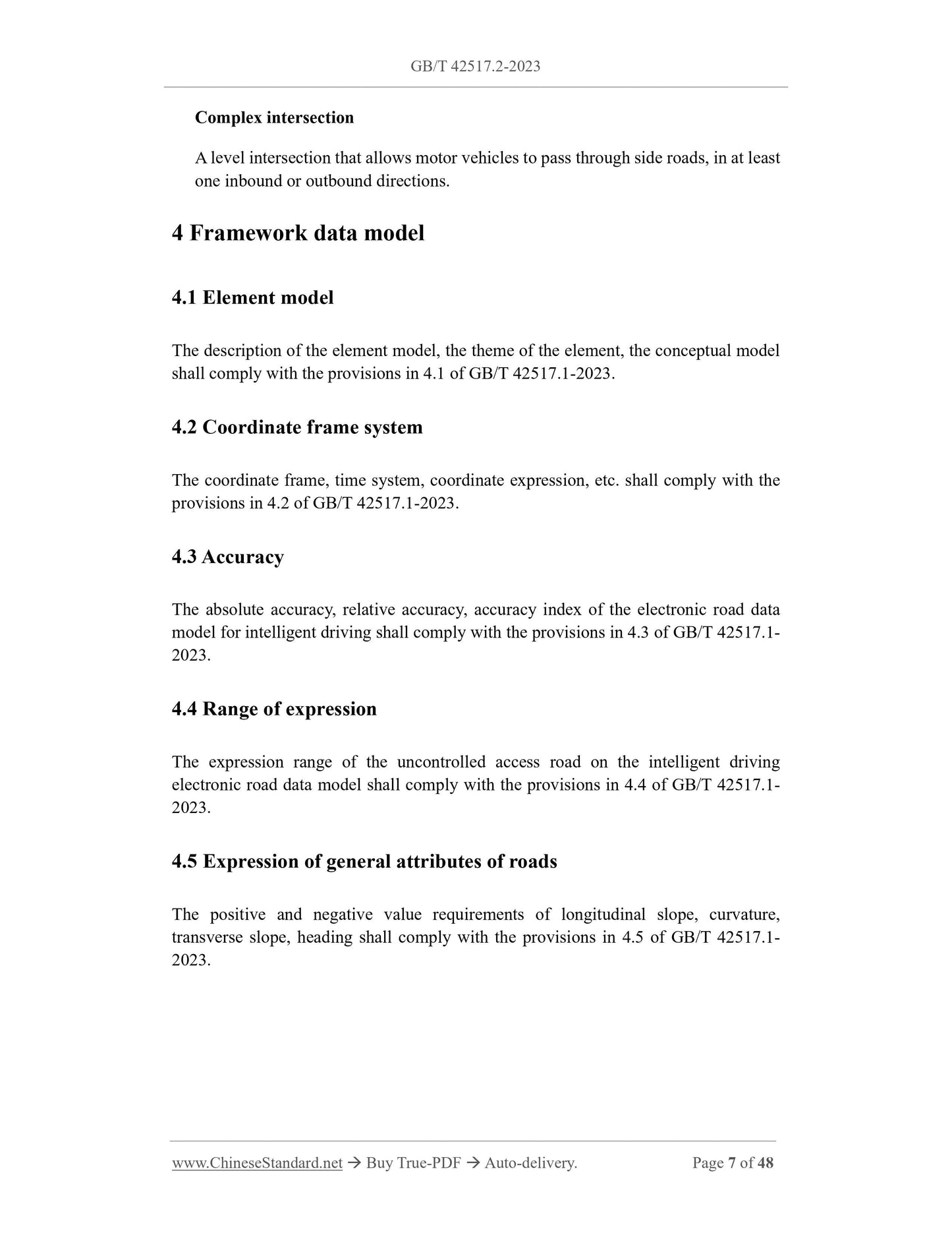
4 Framework data model
4:1 Element model
The description of the element model, the theme of the element and the conceptual model shall comply with the provisions in 4:1 of GB/T 42517:1-2023:
4:2 Coordinate frame system
The coordinate frame, time system, coordinate expression, etc: shall comply with the provisions in 4:2 of GB/T 42517:1-2023:
4:3 Accuracy
The absolute accuracy, relative accuracy and accuracy indicators of the electronic road map for intelligent driving shall comply with the provisions in 4:3 of GB/T 42517:1-2023

View full details