1
/
of
7
www.ChineseStandard.us -- Field Test Asia Pte. Ltd.
GB/T 4206-1984 English PDF (GB/T4206-1984)
GB/T 4206-1984 English PDF (GB/T4206-1984)
Regular price
$125.00
Regular price
Sale price
$125.00
Unit price
/
per
Shipping calculated at checkout.
Couldn't load pickup availability
GB/T 4206-1984: Silicone resin glass laminated sheets
Delivery: 9 seconds. Download (and Email) true-PDF + Invoice.Get Quotation: Click GB/T 4206-1984 (Self-service in 1-minute)
Newer / historical versions: GB/T 4206-1984
Preview True-PDF
Scope
1.1 AppearanceThe edges of the laminated sheets shall be cut in order; and there shall be no
delamination and crack in the cross section.
There shall be no bubbles, wrinkles, or pockmarks on the surface of the laminated sheets;
slight scratches, pits and color difference are allowed; and a small amount of splashes
are allowed.
1.2 Dimensions and deviations
1.2.1 Width and length:
The scope of the width and the length of the laminated sheets and the deviation of the
corresponding size shall be in accordance with the provisions of Table 1.
2.2 Appearance
The appearance shall be evaluated by eye observation.
2.3 Machining
The machining shall be carried out through negotiation by the supplier and the buyer.
2.4 Determination of bending strength of vertical sheet
The bending strength of vertical sheet shall be tested according to the test method for
bending strength in GB 1304-77 "General Test Method for Electrical Insulation and
Thermosetting Laminated Products".
The samples shall be cut from the test sheet, 5 samples longitudinally and 5 samples
transversely. If the thickness of the test sheet h is more than 10mm, the samples shall be
processed to be 10 ± 0.5mm from one side of the sheet. The size of the samples shall be:
Length: L = 20hmm 2 (h shall be accurate to 0.02mm)
Width: b = 1.5 ± 0.5mm
Adjust the support span (L1), to make the L1 = 16hmm, and measure the span to be
accurate to be within 0.5%.
Place the samples under the conditions of 23 ± 2°C and 45%~55% relative humidity for at
least 24 hours; start the test within 3 minutes after taking the samples out of the
environment. Apply load to the vertical sheet. Calculate the average values of the
longitudinal and transverse directions respectively; take the smaller value as the test
result.
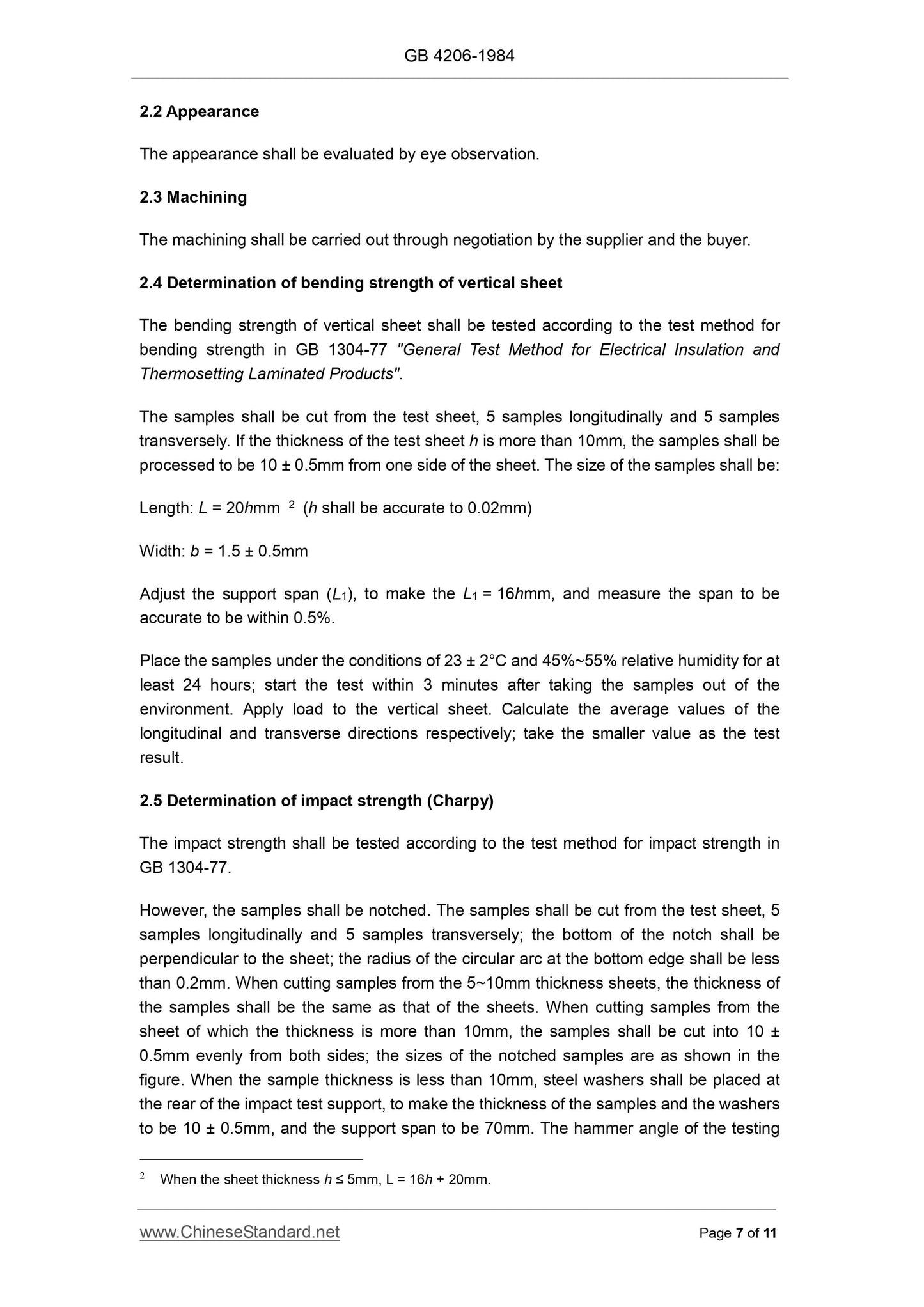
2.5 Determination of impact strength (Charpy)
The impact strength shall be tested according to the test method for impact strength in
GB 1304-77.
However, the samples shall be notched. The samples shall be cut from the test sheet, 5
samples longitudinally and 5 samples transversely; the bottom of the notch shall be
perpendicular to the sheet; the radius of the circular arc at the bottom edge shall be less
than 0.2mm. When cutting samples from the 5~10mm thickness sheets, the thickness of
the samples shall be the same as that of the sheets. When cutting samples from the
sheet of which the thickness is more than 10mm, the samples shall be cut into 10 ±
0.5mm evenly from both sides; the sizes of the notched samples are as shown in the
figure. When the sample thickness is less than 10mm, steel washers shall be placed at
the rear of the impact test support, to make the thickness of the samples and the washers
to be 10 ± 0.5mm, and the support span to be 70mm. The hammer angle of the testing
2 When the sheet thickness h ≤ 5mm, L = 16h + 20mm.
Method for Solid Electrical Insulation Materials".
The samples length shall be 100mm; the width shall be 25 ± 0.2mm; and the thickness
shall be the same as the test sheet. Take three samples; cut the two long sides of the
samples into two parallel planes perpendicular to the surface of the material. Place the
samples between two parallel metal plate electrodes; apply voltage to the 25mm wide
samples between the two electrodes. For thin material, two samples can be properly
placed (that is, to form a proper angle with their long sides) to support the electrodes. The
electrodes shall be sufficiently large in size, so as to cover at least 15mm of each side of
the samples.
The samples shall be treated under the conditions of 50 ± 2°C and relative humidity less
than 20% for 24 hours; after the samples cool to room temperature, immerse the samples
into the 90 ± 2°C transformer oil for 0.5~1 hour; then carry out the voltage resistance test
immediately in the oil for 1 minute. The test result is qualified only when none of the three
samples is broken down, expressed in kV.
2.7 Determination of insulation resistance in parallel after immersion
The insulation resistance in parallel after immersion shall be tested according to GB
1410-78 "Test Method for Insulation Resistance, Volume Resistance and Surface
Resistance Coefficient of Solid Electrical Insulation Materials".
The samples length shall be ; the width shall be ; and the thickness
shall be the same as the test sheet. Take 4 samples, 2 longitudinal and 2 transverse. The
samples shall be treated under the conditions of 50 ± 2°C and relative humidity less than
20% for 24 hours; after the samples cool to room temperature, immerse the samples into
23 ± 2°C distilled water for 24 ± 1 hours. Take out the samples from the water; dry the
samples with clean cloth or filter paper; insert the electrodes; the electrodes distance
shall be 25 ± 1mm; measure the insulation resistance under the conditions of relative
humidity not more than 75% and 15 ~ 35°C; apply external voltage 500 ± 12V; the
determination shall be completed within 1.5 ~ 2 minutes after the samples are taken from
the water. Calculate the average values of the longitudinal and transverse directions
respectively; take the smaller value as the test result.
2.8 Determination of 1MHz dielectric loss angle tangent and relative dielectric
coefficient after immersion
The 1MHz dielectric loss angle tangent and relative dielectric coefficient after immersion
shall be tested according to GB 1409-78 "Test Methods for Dielectric Coefficient and
Dielectric Loss Angle Tangent of Solid Electrical Insulating Materials at Power Frequency,
Audio Frequency, and High Frequency".
The samples size shall be 55mm x 55mm; two samples shall be tested. The diameter of
the oil aluminum foil electrodes used in the test shall be 50 ± 0.1mm. The samples shall
be treated under the conditions of 50 ± 2°C and relative humidity less than 20% for 24
hours; after the samples are cooled to room temperature; immerse the samples into 23 ±
2°C distilled water for 24 hours; then take out the samples from the water; dry the
samples with clean cloth, blotter or filter paper. Add the electrodes into the samples after
immersion; complete the test and reading at 1MHz within 20 minutes after taking out the
samples. The test environment shall be at temperature of 23 ± 2°C and relative humidity
of 45%~55%. Take two average values of the dielectric loss angle tangent and two
average values of the relative dielectric coefficient as the test results.
2.9 Determination of water absorption
2.9.1 Instruments
a. Balance, sensibility is not more than 1mg;
b. Oven, controllable temperature of 50 ± 2°C;
c. Container, with a controllable temperature of 23 ± 0.5°C;
d. Drier.
2.9.2 Samples
50 ± 1mm square, take 3. The thickness of the samples shall be the same as that of the
test sheet, and the section shall be smooth.
2.9.3 Test procedures
Dry the samples in 50 ± 2°C oven for 24 ± 1 hours; cool the samples in the oven; weigh
every sample, accurate to 1mg; then place the samples into the container with distilled
water; control the water temperature at 23 ± 0.5°C; after 24 ± 1 hours, take the samples
out of the water; wipe all the surface moisture with a piece of clean cloth or filter paper;
and reweigh the samples within 1 minute.
Note: The samples can be weighted in the weighing bottles when necessary.
2.9.4 Expression of calculation and results
m = m2 - m1
Where:
m — Water absorption of samples, mg;
m1 — Weight of samples before immersion, mg;
m2 — Weight of samples after immersion, mg.
Take three arithmetic mean values of the samples as the test results.
Basic Data
| Standard ID | GB/T 4206-1984 (GB/T4206-1984) |
| Description (Translated English) | Silicone resin glass laminated sheets |
| Sector / Industry | National Standard (Recommended) |
| Classification of Chinese Standard | K15 |
| Classification of International Standard | 29.040.20 |
| Word Count Estimation | 7,738 |
| Date of Issue | 3/19/1984 |
| Date of Implementation | 12/1/1984 |
| Adopted Standard | ISO 1642-1979, MOD |
| Regulation (derived from) | Announcement of Newly Approved National Standards 2009 No. 8 (No. 148 overall) |
| Issuing agency(ies) | National Bureau of Standards |
Share