Skip to product information
1 of 7

PayPal, credit cards. Download editable-PDF and invoice in 1 second!

GB/T 41722-2022 English PDF (GBT41722-2022)

GB/T 41722-2022 English PDF (GBT41722-2022)

Regular price $155.00 USD
Regular price Sale price $155.00 USD
Sale Sold out
Shipping calculated at checkout.
Quotation: In 1-minute, 24-hr self-service. Click here GB/T 41722-2022 to get it for Purchase Approval, Bank TT...

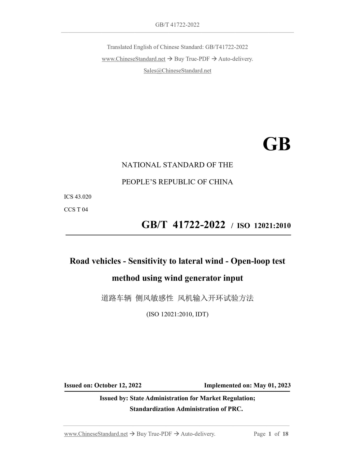
GB/T 41722-2022: Road vehicles -- Sensitivity to lateral wind -- Open-loop test method using wind generator input

This document specifies an open-loop test method for lateral wind susceptibility testing of vehicles, as produced by wind generator. This document is applicable to M1 and N1 category vehicles. It also applies to passenger car combinations. Other types of vehicles can be implemented with reference to this document. Note: The test conditions, which are specified in this document, do not represent the real driving conditions; it can be used to quantitatively test the response of the vehicle to the lateral wind. The lateral wind conditions, which are specified in this document, are not directly simulating natural wind conditions; the specified wind speeds are equivalent to harsher conditions under natural conditions.
GB/T 41722-2022
GB
NATIONAL STANDARD OF THE
PEOPLE’S REPUBLIC OF CHINA
ICS 43.020
CCS T 04
GB/T 41722-2022 / ISO 12021:2010
Road vehicles - Sensitivity to lateral wind - Open-loop test
method using wind generator input
(ISO 12021:2010, IDT)
ISSUED ON: OCTOBER 12, 2022
IMPLEMENTED ON: MAY 01, 2023
Issued by: State Administration for Market Regulation;
Standardization Administration of PRC.
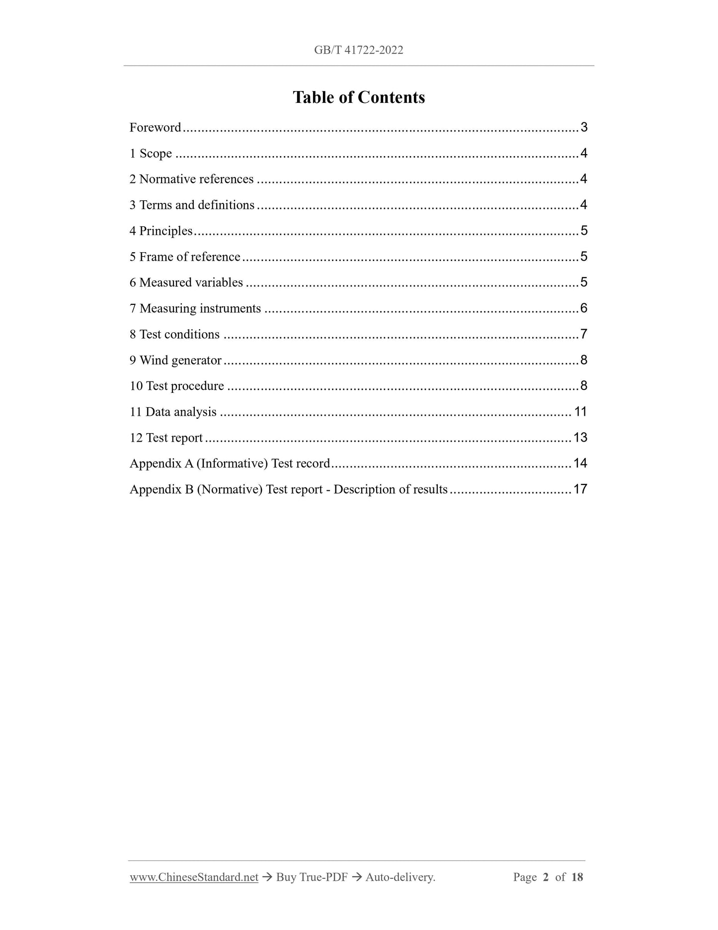
Table of Contents
Foreword ... 3
1 Scope ... 4
2 Normative references ... 4
3 Terms and definitions ... 4
4 Principles ... 5
5 Frame of reference ... 5
6 Measured variables ... 5
7 Measuring instruments ... 6
8 Test conditions ... 7
9 Wind generator ... 8
10 Test procedure ... 8
11 Data analysis ... 11
12 Test report ... 13
Appendix A (Informative) Test record ... 14
Appendix B (Normative) Test report - Description of results ... 17
Road vehicles - Sensitivity to lateral wind - Open-loop test
method using wind generator input
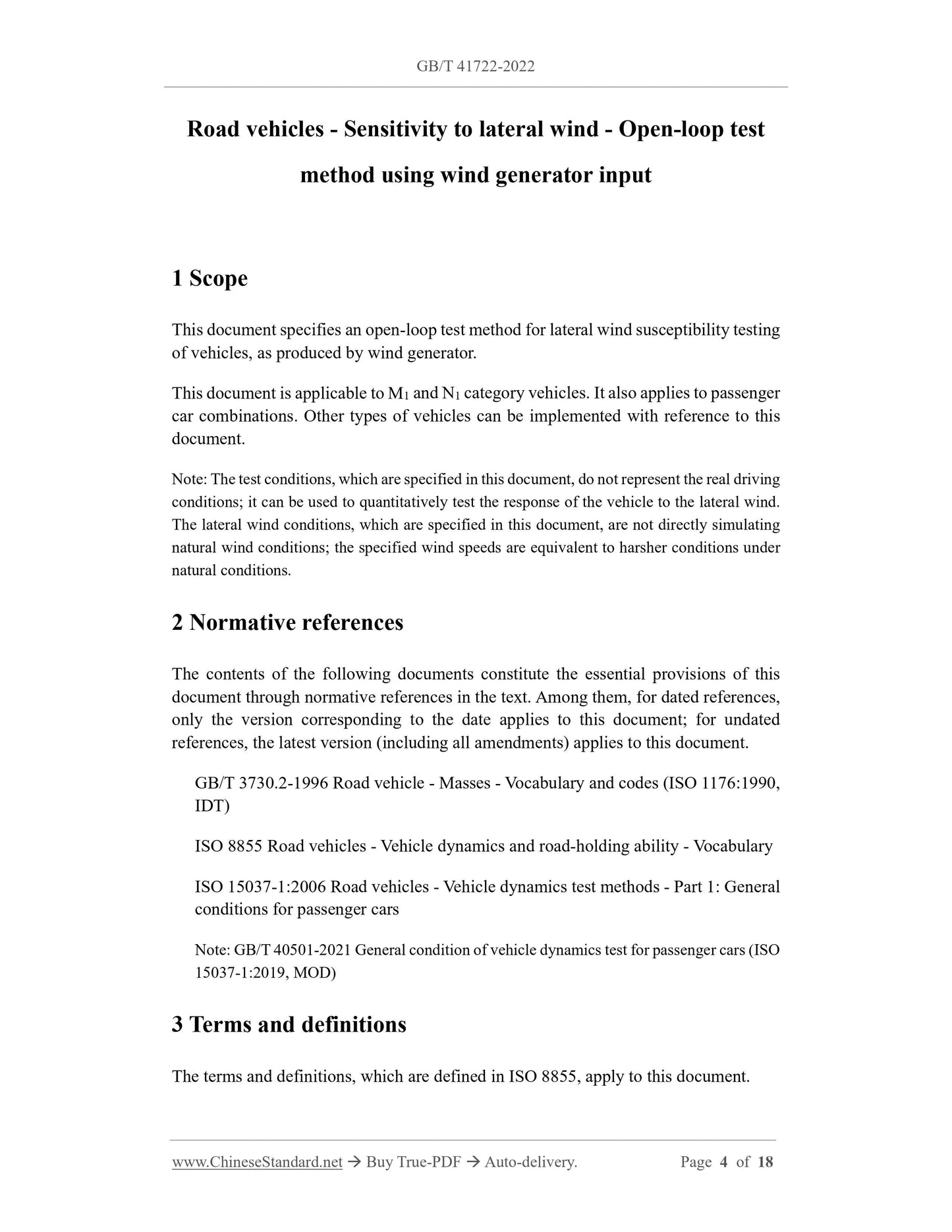
1 Scope
This document specifies an open-loop test method for lateral wind susceptibility testing of vehicles, as produced by wind generator.
This document is applicable to M1 and N1 category vehicles. It also applies to passenger car combinations. Other types of vehicles can be implemented with reference to this document.
Note: The test conditions, which are specified in this document, do not represent the real driving conditions; it can be used to quantitatively test the response of the vehicle to the lateral wind. The lateral wind conditions, which are specified in this document, are not directly simulating natural wind conditions; the specified wind speeds are equivalent to harsher conditions under natural conditions.
2 Normative references
The contents of the following documents constitute the essential provisions of this document through normative references in the text. Among them, for dated references, only the version corresponding to the date applies to this document; for undated references, the latest version (including all amendments) applies to this document. GB/T 3730.2-1996 Road vehicle - Masses - Vocabulary and codes (ISO 1176:1990, IDT)
ISO 8855 Road vehicles - Vehicle dynamics and road-holding ability - Vocabulary ISO 15037-1:2006 Road vehicles - Vehicle dynamics test methods - Part 1: General conditions for passenger cars
Note: GB/T 40501-2021 General condition of vehicle dynamics test for passenger cars (ISO 15037-1:2019, MOD)
3 Terms and definitions
The terms and definitions, which are defined in ISO 8855, apply to this document. 4 Principles
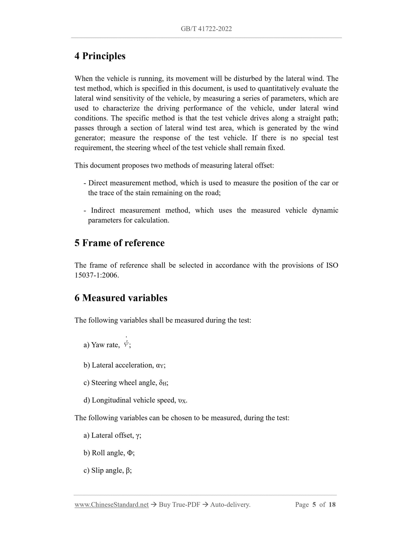
When the vehicle is running, its movement will be disturbed by the lateral wind. The test method, which is specified in this document, is used to quantitatively evaluate the lateral wind sensitivity of the vehicle, by measuring a series of parameters, which are used to characterize the driving performance of the vehicle, under lateral wind conditions. The specific method is that the test vehicle drives along a straight path; passes through a section of lateral wind test area, which is generated by the wind generator; measure the response of the test vehicle. If there is no special test requirement, the steering wheel of the test vehicle shall remain fixed. This document proposes two methods of measuring lateral offset:
- Direct measurement method, which is used to measure the position of the car or the trace of the stain remaining on the road;
- Indirect measurement method, which uses the measured vehicle dynamic
parameters for calculation.
5 Frame of reference
The frame of reference shall be selected in accordance with the provisions of ISO 15037-1:2006.
6 Measured variables
The following variables shall be measured during the test:
a) Yaw rate, ;
b) Lateral acceleration, αY;
c) Steering wheel angle, δH;
d) Longitudinal vehicle speed, υX.
The following variables can be chosen to be measured, during the test:
a) Lateral offset, γ;
b) Roll angle, Φ;
c) Slip angle, β;
The location of the sprinkler installation point shall be close to the Z axis of the intermediate coordinate system. If it cannot be realized, it can be corrected, to obtain the lateral acceleration data within the tolerance range.
7.3 Data processing
It shall comply with the recording system and data processing requirements contained in 4.3 of ISO 15037-1:2006.
8 Test conditions
8.1 General requirements
The test conditions shall be carried out, in accordance with 5.1 of ISO 15037-1:2006 AND 8.2 and 8.3 of this document. Any test deviations shall be recorded in the test report (see Appendix A) and a chart describing the respective results (see Appendix B). 8.2 Test road
The test shall be carried out on a clean and pollution-free road pavement, which has uniform hardness. The transverse gradient of the test road and the longitudinal gradient between any 50 m shall be less than 2.5%.
The pavement of the test road shall be a flat asphalt or concrete surface or other high friction surface.
The test road pavement shall be within the range from at least 100 m in front of the lateral wind area to 100 m behind the lateral wind area; the width shall not be less than 5 m; the width of the test road, behind the lateral wind area, shall not be less than 7 m. In addition to the specified test road pavement conditions, the test road shall have a sufficient buffer zone.
8.3 Climatic conditions
The ambient wind speed should be as small as possible during the test; the wind speed in any direction shall not exceed 3 m/s. Under the standard test conditions, dry pavement should be used; wet pavement without obvious water accumulation can also be used.
Climatic conditions shall be recorded in the test report (see Appendix A). 8.4 Test vehicle
It shall meet the requirements of 5.4 in ISO 15037-1:2006.
8.5 Vehicle load status
8.5.1 General requirements
The test shall be carried out under the minimum load state defined in 8.5.2 and the maximum load state defined in 8.5.3. It may also be carried out under other load states as required.
It shall not exceed the maximum allowable total mass and maximum allowable axle load, which are defined in 4.8 and 4.13 of GB/T 3730.2-1996.
During the test, the vehicle load shall be reasonably arranged, so that the position of the center of gravity and the moment of inertia do not shift as far as possible, as compared with the normal load state. The wheel load shall be measured during the test AND recorded in the test report (see Appendix A).
8.5.2 Minimum load state
Under the minimum load state, the total mass of the test vehicle shall include the curb mass of the vehicle, the mass of the driver, the instruments and equipment. The total mass of the driver and equipment should not exceed 150 kg.
8.5.3 Maximum load state
Under the maximum load state, the total mass of the test vehicle shall be the maximum allowable total mass.
9 Wind generator
The lateral wind of the test is generated by the wind generator. the average wind speed of the lateral wind shall reach 20 m/s ± 3 m/s (under the condition that the wind speed of the surrounding environment is less than 1 m/s). The profile for calculating the average wind speed shall be along the reference driving line, covering the length of the lateral wind area and the height of the test vehicle. The nominal wind direction angle, as relative to the reference travel line, AND the wind speed profile, which covers the length and height range of the entire lateral wind area, shall be recorded in the test report (see Appendix A). The nominal length of the lateral wind area is generally determined by the wind generator array; the nominal length shall not be less than 15 m, preferably greater than 25 m. The nominal length of the lateral wind area shall be recorded in the test report (see Appendix A).
10 Test procedure
10.1 Warm-up
It shall meet the requirements of 6.1 in ISO 15037-1:2006.
11 Data analysis
11.1 General requirements
Test results shall be recorded in the form of peak or pulse values (see Figure 2). If the peak value is used, the bandwidth of the measurement system shall be considered; a small bandwidth is recommended.
11.2 Yaw rate and lateral acceleration
See Appendix B for the record form of yaw rate and lateral acceleration. If it is required to calculate the pulse value of yaw rate and lateral acceleration, the method is as follows. The pulse value is defined as the average signal value, during the period when the signal value exceeds 50% of the peak value (see Figure 2). First, take the signal zero value as the initial reference value, to define the maximum output time tpeak and the initial peak value (see Figure 2). The time point t0 shall first be defined as the point in time, which goes back along the time axis, when the signal value starts to drop below 0.15 times the peak value. Because the steering wheel will be fixed, from 40 m before the starting point of the lateral wind area (see 10.3), the reference value of the output signal is the average value -- of the signal value which is calculated from 0.2 s after the time point t-40 to 0.2 s before the time point t0. Note that the speed value, at time point t-40, depends on the longitudinal vehicle speed; however, it can also be calculated using the test vehicle speed.
The following parameters can be iteratively calculated, using this reference value: - Peak value;
- t0;
- New reference value.
It is until the difference -- between two consecutive reference values -- is less than 0.5% of the peak value. The final reference value will be used in the calculation of the final peak and pulse values.
If there are other measured variables, the signal peak value and pulse value of this variable shall be calculated together.

View full details