Skip to product information
1 of 7

www.ChineseStandard.us -- Field Test Asia Pte. Ltd.

GB/T 41607-2022 English PDF (GB/T41607-2022)

GB/T 41607-2022 English PDF (GB/T41607-2022)

Regular price $260.00
Regular price Sale price $260.00
Sale Sold out
Shipping calculated at checkout.
GB/T 41607-2022: Test method for inertia absorption durability of friction elements in wet automatic transmission
Delivery: 9 seconds. Download (& Email) true-PDF + Invoice.
Get Quotation: Click GB/T 41607-2022 (Self-service in 1-minute)
Historical versions (Master-website): GB/T 41607-2022
Preview True-PDF (Reload/Scroll-down if blank)

GB/T 41607-2022
NATIONAL STANDARD OF THE
PEOPLE’S REPUBLIC OF CHINA
ICS 43.040.40
CCS Q 69
Test method for inertia absorption durability of friction
elements in wet automatic transmission
ISSUED ON: JULY 11, 2022
IMPLEMENTED ON: FEBRUARY 01, 2023
Issued by: State Administration for Market Regulation;
Standardization Administration of the People’s Republic of China.
Table of Contents
Foreword ... 3 
1 Scope ... 4 
2 Normative references ... 4 
3 Terms and definitions... 4 
4 Test equipment and preparation ... 7 
5 Test procedures ... 12 
6 Test data ... 13 
7 Precision ... 15 
8 Test report ... 15 
Appendix A (Normative) Size and requirements of friction plate and dual plate ... 16 
Appendix B (Informative) Test report sample form ... 18 
References ... 20 
Test method for inertia absorption durability of friction
elements in wet automatic transmission
1 Scope
This document specifies the test equipment and preparation, test procedures, test data,
precision and test report of the test method for the inertia absorption durability of
friction elements in wet automatic transmission.
This document applies to the determination of the inertia absorption durability
performance of friction elements in automatic transmissions for passenger cars and
commercial vehicles. It can be used as a reference for other types of friction elements
in automatic transmissions.
2 Normative references
The following documents, in whole or in part, are normatively referenced in this
document and are indispensable for its application. For dated references, only the
version corresponding to that date is applicable to this document; for undated references,
the latest version (including all amendments) is applicable to this document.
GB/T 8170, Rules of rounding off for numerical values and expression and judgment
of limiting values
3 Terms and definitions
The following terms and definitions are applicable to this document.
3.1
Friction characteristics
The unique intrinsic properties of friction materials (friction elements) shown in the
friction process.
Note: In this document, dynamic and static friction tests are used to evaluate the friction
characteristics of friction elements in automatic transmissions.
3.2
Friction coefficient
The ratio of the friction force generated TO the force exerted on the friction element
when there is relative movement or relative movement tendency between the friction
plate and the dual plate.
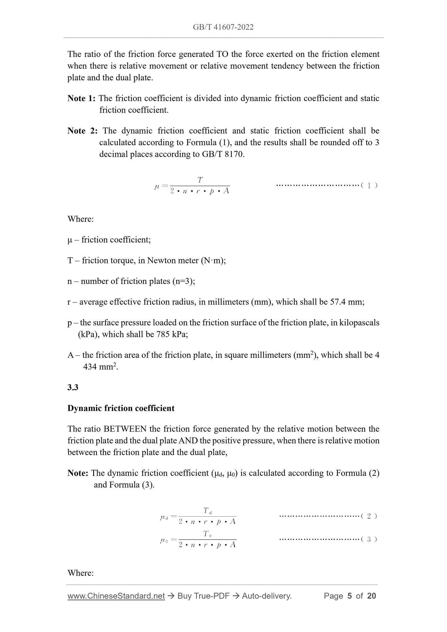
Note 1: The friction coefficient is divided into dynamic friction coefficient and static
friction coefficient.
Note 2: The dynamic friction coefficient and static friction coefficient shall be
calculated according to Formula (1), and the results shall be rounded off to 3
decimal places according to GB/T 8170.
Where:
μ – friction coefficient;
T – friction torque, in Newton meter (N·m);
n – number of friction plates (n=3);
r – average effective friction radius, in millimeters (mm), which shall be 57.4 mm;
p – the surface pressure loaded on the friction surface of the friction plate, in kilopascals
(kPa), which shall be 785 kPa;
A – the friction area of the friction plate, in square millimeters (mm2), which shall be 4
434 mm2.
3.3
Dynamic friction coefficient
The ratio BETWEEN the friction force generated by the relative motion between the
friction plate and the dual plate AND the positive pressure, when there is relative motion
between the friction plate and the dual plate,
Note: The dynamic friction coefficient (μd, μ0) is calculated according to Formula (2)
and Formula (3).
Where:
4.2 Test preparation
4.2.1 Friction plate preparation
The size of the friction plate shall meet the requirements of A.1 in Appendix A.
Soak the friction plate which is stored in the desiccator in the test oil for more than 2 h;
take it out and wipe the test oil. Then, use a micrometer to measure the thickness of the
friction plate at four points every 90°, accurate to 0.001 mm. Mark test points on
surfaces that are not rubbed.
4.2.2 Dual plate preparation
The size of the dual plate shall meet the requirements of A.2.
The dual plate used shall be cleaned of oil on the surface using ultrasonic waves in a
solvent such as hexane, wiped with lint-free paper, and dried at room temperature.
4.2.3 Testing machine preparation
After each test, the test oil chamber and each oil pipe shall be thoroughly cleaned and
dried with a solvent such as hexane. When measuring the oil temperature, the
thermocouple shall be fixed at a position 2 mm from the end face and horizontal to the
test oil chamber.
4.2.4 Installation of friction components
Install the friction plate and the dual plate one by one; pay attention to adjusting the
friction gap at the position of 0.8 mm ± 0.2 mm.
The dual plate and friction plate shall be installed as shown in Figure 5; pay attention
to the installation direction (A, B and A’, B’ in Figure 5); the clearance between the
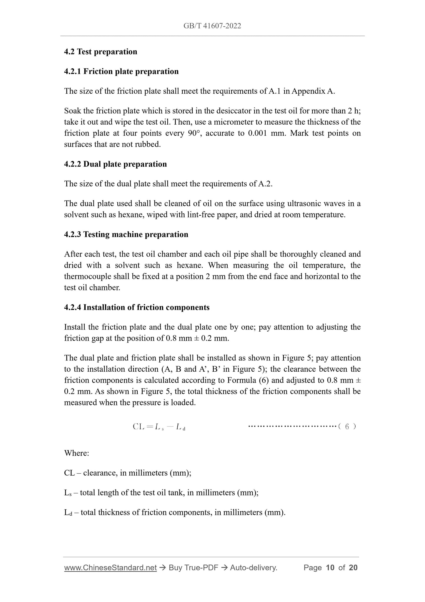
friction components is calculated according to Formula (6) and adjusted to 0.8 mm ±
0.2 mm. As shown in Figure 5, the total thickness of the friction components shall be
measured when the pressure is loaded.
Where:
CL – clearance, in millimeters (mm);
Ls – total length of the test oil tank, in millimeters (mm);
Ld – total thickness of friction components, in millimeters (mm).
6.2.1 Friction plate
After 5 000 times of braking, observe the 6 faces of the friction plate, observe and record
the following conditions:
a) Wear and tear of the friction plate;
b) Discoloration or ablation on the surface of the friction plate;
c) Whether there is material peeling on the friction surface;
d) Whether there is blocking on the surface of the friction material.
6.2.2 Dual plate
After 5 000 times of braking, observe the 8 faces of the dual plate, observe and record
the following conditions:
a) Wear and tear of the dual plate;
b) Discoloration on the surface of the dual plate, and whether there is a high
temperature ablation point.
6.3 Record
6.3.1 Test curve
Curves of torque, revolutions and pressure generated in the 1st, 50th, 200th, 500th, 1 000th,
3 000th, and 5 000th test cycles of the dynamic friction test and the static friction test.
6.3.2 Calculation results
6.3.2.1 Calculate Rd according to Formula (7), round off the result to 2 decimal places
according to GB/T8170.
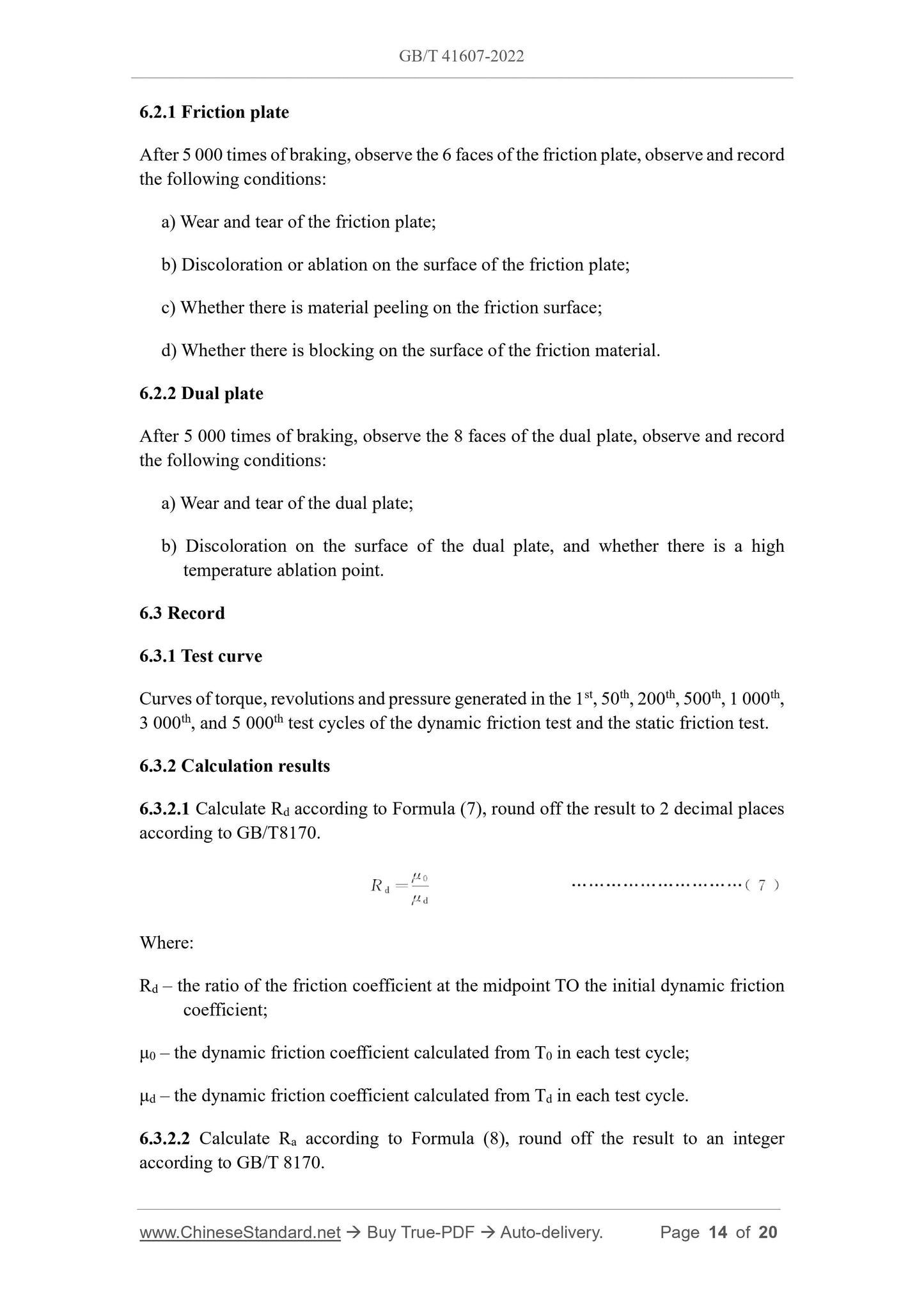
Where:
Rd – the ratio of the friction coefficient at the midpoint TO the initial dynamic friction
coefficient;
μ0 – the dynamic friction coefficient calculated from T0 in each test cycle;
μd – the dynamic friction coefficient calculated from Td in each test cycle.
6.3.2.2 Calculate Ra according to Formula (8), round off the result to an integer
according to GB/T 8170.
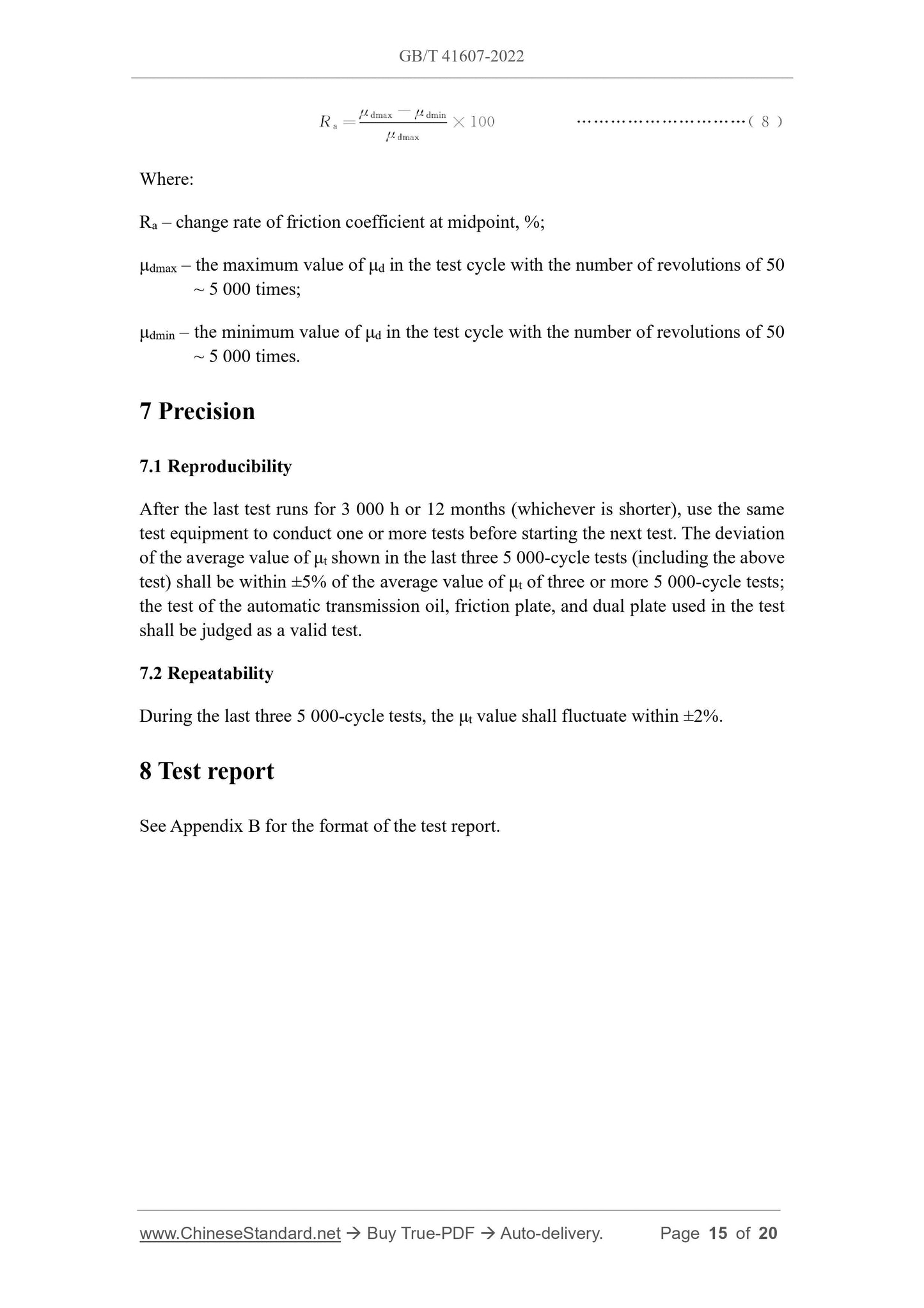
Where:
Ra – change rate of friction coefficient at midpoint, %;
μdmax – the maximum value of μd in the test cycle with the number of revolutions of 50
~ 5 000 times;
μdmin – the minimum value of μd in the test cycle with the number of revolutions of 50
~ 5 000 times.
7 Precision
7.1 Reproducibility
After the last test runs for 3 000 h or 12 months (whichever is shorter), use the same
test equipment to conduct one or more tests before starting the next test. The deviation
of the average value of μt shown in the last three 5 000-cycle tests (including the above
test) shall be within ±5% of the average value of μt of three or more 5 000-cycle tests;
the test of the automatic transmission oil, friction plate, and dual plate used in the test
shall be judged as a valid test.
7.2 Repeatability
During the last three 5 000-cycle tests, the μt value shall fluctuate within ±2%.
8 Test report
See Appendix B for the format of the test report.
GB/T 41607-2022
NATIONAL STANDARD OF THE
PEOPLE’S REPUBLIC OF CHINA
ICS 43.040.40
CCS Q 69
Test method for inertia absorption durability of friction
elements in wet automatic transmission
ISSUED ON: JULY 11, 2022
IMPLEMENTED ON: FEBRUARY 01, 2023
Issued by: State Administration for Market Regulation;
Standardization Administration of the People’s Republic of China.
Table of Contents
Foreword ... 3 
1 Scope ... 4 
2 Normative references ... 4 
3 Terms and definitions... 4 
4 Test equipment and preparation ... 7 
5 Test procedures ... 12 
6 Test data ... 13 
7 Precision ... 15 
8 Test report ... 15 
Appendix A (Normative) Size and requirements of friction plate and dual plate ... 16 
Appendix B (Informative) Test report sample form ... 18 
References ... 20 
Test method for inertia absorption durability of friction
elements in wet automatic transmission
1 Scope
This document specifies the test equipment and preparation, test procedures, test data,
precision and test report of the test method for the inertia absorption durability of
friction elements in wet automatic transmission.
This document applies to the determination of the inertia absorption durability
performance of friction elements in automatic transmissions for passenger cars and
commercial vehicles. It can be used as a reference for other types of friction elements
in automatic transmissions.
2 Normative references
The following documents, in whole or in part, are normatively referenced in this
document and are indispensable for its application. For dated references, only the
version corresponding to that date is applicable to this document; for undated references,
the latest version (including all amendments) is applicable to this document.
GB/T 8170, Rules of rounding off for numerical values and expression and judgment
of limiting values
3 Terms and definitions
The following terms and definitions are applicable to this document.
3.1
Friction characteristics
The unique intrinsic properties of friction materials (friction elements) shown in the
friction process.
Note: In this document, dynamic and static friction tests are used to evaluate the friction
characteristics of friction elements in automatic transmissions.
3.2
Friction coefficient
The ratio of the friction force generated TO the force exerted on the friction element
when there is relative movement or relative movement tendency between the friction
plate and the dual plate.
Note 1: The friction coefficient is divided into dynamic friction coefficient and static
friction coefficient.
Note 2: The dynamic friction coefficient and static friction coefficient shall be
calculated according to Formula (1), and the results shall be rounded off to 3
decimal places according to GB/T 8170.
Where:
μ – friction coefficient;
T – friction torque, in Newton meter (N·m);
n – number of friction plates (n=3);
r – average effective friction radius, in millimeters (mm), which shall be 57.4 mm;
p – the surface pressure loaded on the friction surface of the friction plate, in kilopascals
(kPa), which shall be 785 kPa;
A – the friction area of the friction plate, in square millimeters (mm2), which shall be 4
434 mm2.
3.3
Dynamic friction coefficient
The ratio BETWEEN the friction force generated by the relative motion between the
friction plate and the dual plate AND the positive pressure, when there is relative motion
between the friction plate and the dual plate,
Note: The dynamic friction coefficient (μd, μ0) is calculated according to Formula (2)
and Formula (3).
Where:
4.2 Test preparation
4.2.1 Friction plate preparation
The size of the friction plate shall meet the requirements of A.1 in Appendix A.
Soak the friction plate which is stored in the desiccator in the test oil for more than 2 h;
take it out and wipe the test oil. Then, use a micrometer to measure the thickness of the
friction plate at four points every 90°, accurate to 0.001 mm. Mark test points on
surfaces that are not rubbed.
4.2.2 Dual plate preparation
The size of the dual plate shall meet the requirements of A.2.
The dual plate used shall be cleaned of oil on the surface using ultrasonic waves in a
solvent such as hexane, wiped with lint-free paper, and dried at room temperature.
4.2.3 Testing machine preparation
After each test, the test oil chamber and each oil pipe shall be thoroughly cleaned and
dried with a solvent such as hexane. When measuring the oil temperature, the
thermocouple shall be fixed at a position 2 mm from the end face and horizontal to the
test oil chamber.
4.2.4 Installation of friction components
Install the friction plate and the dual plate one by one; pay attention to adjusting the
friction gap at the position of 0.8 mm ± 0.2 mm.
The dual plate and friction plate shall be installed as shown in Figure 5; pay attention
to the installation direction (A, B and A’, B’ in Figure 5); the clearance between the
friction components is calculated according to Formula (6) and adjusted to 0.8 mm ±
0.2 mm. As shown in Figure 5, the total thickness of the friction components shall be
measured when the pressure is loaded.
Where:
CL – clearance, in millimeters (mm);
Ls – total length of the test oil tank, in millimeters (mm);
Ld – total thickness of friction components, in millimeters (mm).
6.2.1 Friction plate
After 5 000 times of braking, observe the 6 faces of the friction plate, observe and record
the following conditions:
a) Wear and tear of the friction plate;
b) Discoloration or ablation on the surface of the friction plate;
c) Whether there is material peeling on the friction surface;
d) Whether there is blocking on the surface of the friction material.
6.2.2 Dual plate
After 5 000 times of braking, observe the 8 faces of the dual plate, observe and record
the following conditions:
a) Wear and tear of the dual plate;
b) Discoloration on the surface of the dual plate, and whether there is a high
temperature ablation point.
6.3 Record
6.3.1 Test curve
Curves of torque, revolutions and pressure generated in the 1st, 50th, 200th, 500th, 1 000th,
3 000th, and 5 000th test cycles of...
View full details