Skip to product information
1 of 9

PayPal, credit cards. Download editable-PDF and invoice in 1 second!

GB/T 41310-2022 English PDF (GBT41310-2022)

GB/T 41310-2022 English PDF (GBT41310-2022)

Regular price $335.00 USD
Regular price Sale price $335.00 USD
Sale Sold out
Shipping calculated at checkout.
Delivery: 3 seconds. Download true-PDF + Invoice.
Get QUOTATION in 1-minute: Click GB/T 41310-2022
Historical versions: GB/T 41310-2022
Preview True-PDF (Reload/Scroll if blank)

GB/T 41310-2022: Image-based test method for vision module photoelectric performance
GB/T 41310-2022
NATIONAL STANDARD OF THE
PEOPLE’S REPUBLIC OF CHINA
ICS 31.260
CCS L 50
Image-based test method for vision module photoelectric
performance
ISSUED ON: MARCH 09, 2022
IMPLEMENTED ON: JANUARY 01, 2023
Issued by: State Administration for Market Regulation;
Standardization Administration of PRC.
Table of Contents
Foreword ... 3 
1 Scope ... 4 
2 Normative references ... 4 
3 Terms and definitions... 4 
4 Fundamentals ... 7 
5 Testing conditions ... 8 
6 Instruments and equipment ... 8 
7 Samples under testing ... 9 
8 Testing procedures ... 10 
8.1 Establish a testing environment ... 10 
8.2 Testing of basic photoelectric parameters ... 11 
8.3 Testing of spatial non-uniformity ... 12 
8.4 Testing of dark current characteristics ... 13 
8.5 Testing of spectral sensitivity ... 13 
9 Data processing ... 14 
9.1 Data processing of basic optoelectronic parameters ... 14 
9.2 Data processing of spatial non-uniformity ... 23 
9.3 Data processing of dark current ... 26 
9.4 Data processing of spectral sensitivity ... 28 
10 Test report ... 29 
References ... 30 
Image-based test method for vision module photoelectric
performance
1 Scope
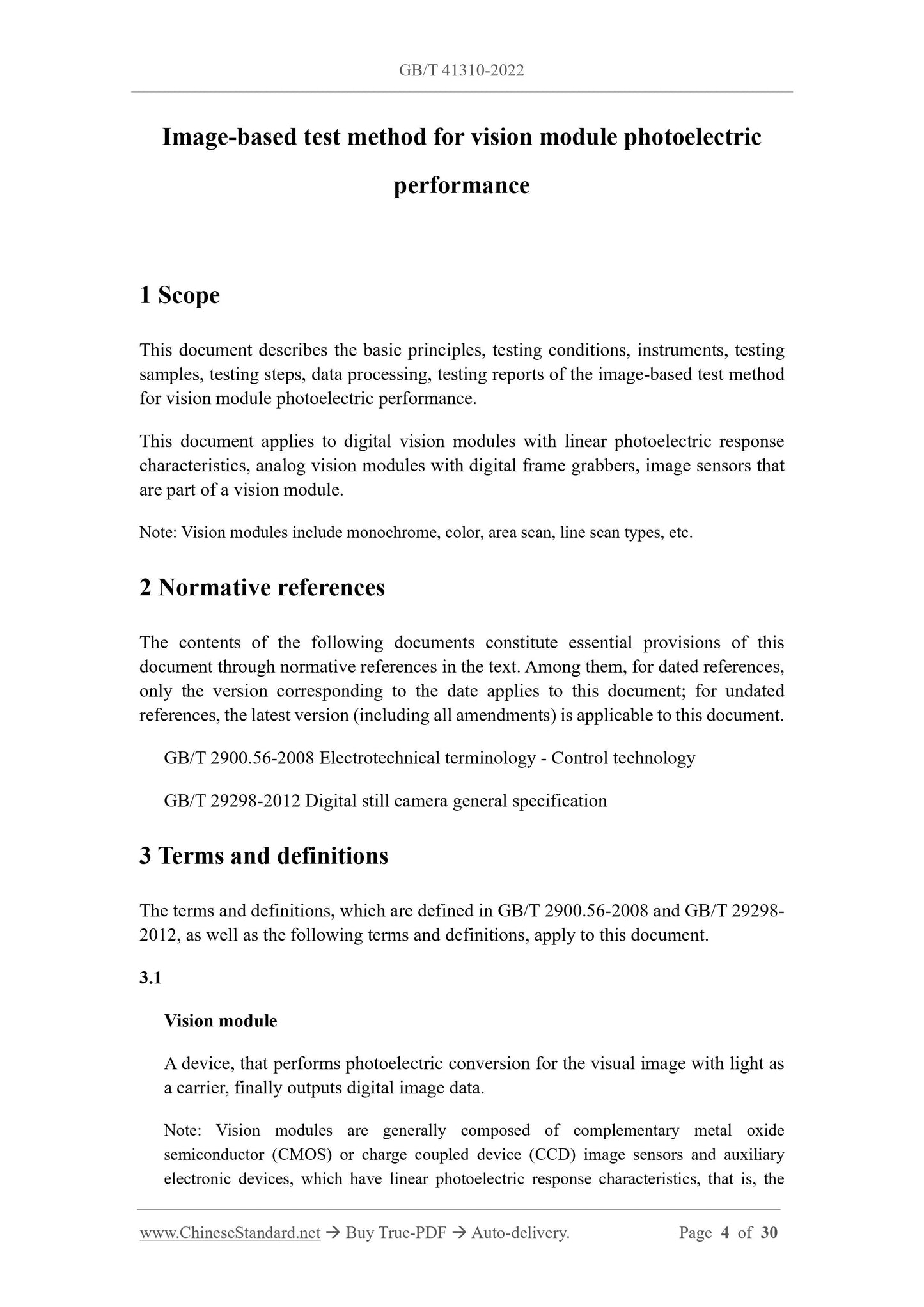
This document describes the basic principles, testing conditions, instruments, testing
samples, testing steps, data processing, testing reports of the image-based test method
for vision module photoelectric performance.
This document applies to digital vision modules with linear photoelectric response
characteristics, analog vision modules with digital frame grabbers, image sensors that
are part of a vision module.
Note: Vision modules include monochrome, color, area scan, line scan types, etc.
2 Normative references
The contents of the following documents constitute essential provisions of this
document through normative references in the text. Among them, for dated references,
only the version corresponding to the date applies to this document; for undated
references, the latest version (including all amendments) is applicable to this document.
GB/T 2900.56-2008 Electrotechnical terminology - Control technology
GB/T 29298-2012 Digital still camera general specification
3 Terms and definitions
The terms and definitions, which are defined in GB/T 2900.56-2008 and GB/T 29298-
2012, as well as the following terms and definitions, apply to this document.
3.1
Vision module
A device, that performs photoelectric conversion for the visual image with light as
a carrier, finally outputs digital image data.
Note: Vision modules are generally composed of complementary metal oxide
semiconductor (CMOS) or charge coupled device (CCD) image sensors and auxiliary
electronic devices, which have linear photoelectric response characteristics, that is, the
the light source shall be selected, as the maximum response wavelength of the
tested sample;
b) When the sample to be tested is a color vision module, light sources with different
wavelengths shall be selected, where each wavelength is close to the maximum
response wavelength of the different color channels of the sample to be tested.
Instruments and equipment, such as light sources, irradiance meters, thermometers,
incubators, shall be regularly calibrated, to ensure the accuracy of data.
7 Samples under testing
During the testing process, the parameter settings of the vision module under testing
meet the following requirements:
a) Temperature: The temperature of the vision module under testing shall be kept
stable, during the testing process;
b) Digital resolution: The pixel bit depth of the vision module under testing shall be
set to the maximum value, to reduce the influence of quantization noise in the test;
c) Gain: Set the gain of the vision module under testing, so that the saturation value
of each pixel reaches the full well and the signal does not overflow;
d) Offset: Set the offset of the vision module under test, so that the number of pixels
with cut-off (gray level is zero value) in the dark signal, which is output by the
vision module under testing, is less than 0.5%;
e) Number of collected lines: A single image of the line array sensor vision module
shall not be less than 100 rows; the calculation formula of the area array sensor is
used, to evaluate the parameters;
f) Radiation exposure: The radiation exposure of the tested sample is controlled, by
the following three methods:
1) Change of exposure time under constant illumination: The brightness of the
light source is fixed; the radiation exposure shall be changed, by adjusting the
exposure time of the tested sample;
2) Illumination change under constant exposure time: The exposure time of the
tested sample is fixed; the radiation exposure shall be changed, by adjusting
the brightness of the light source;
3) Using pulse illumination under constant exposure time: The exposure time of
the sample to be tested is fixed; the radiation exposure shall be changed, by
adjusting the pulse width of the LED light source. The selected exposure time
record the ambient temperature; record the radiation exposure conditions.
c) Follow the steps below for image acquisition:
1) The vision module under test starts to collect images. Turn on the light source.
Increases the radiation exposure, at equal intervals from 0, until the output of
the tested sample is saturated. At this time, the average gray level of the
collected images will not increase. It shall collect at least 10 sets of images
with different radiation exposure levels;
2) Collect two brightfield images, under each radiation exposure condition.
Record the irradiance E, which is measured by the irradiance meter;
3) Turn off the light source. Collect two dark-field images without illumination,
corresponding to the exposure time of each radiation exposure;
4) Turn off the light source. Collect two dark-field images without illumination,
at the shortest exposure time, that can be set for the sample to be tested.
d) Calculate the responsivity, total system gain, quantum efficiency, time-domain
dark noise, absolute sensitivity threshold, saturation capacity, dynamic range,
signal-to-noise ratio, linearity, according to the calculation method of basic
optoelectronic parameters in 9.1.
8.3 Testing of spatial non-uniformity
Carry out testing as follows.
a) Power on all instruments and equipment in the testing environment.
b) Set up the sample to be tested, according to the requirements of Chapter 7. Record
the ambient temperature.
c) Follow the steps below, for image acquisition:
1) The measured vision module starts to collect images. Turn on the light source.
Adjust the radiation exposure, to make the output image of the tested sample
reach 50% of the saturated gray level. At this time, the average gray level of
the collected image is half of the average gray level of the saturated output.
Collect L (L ≥ 16) brightfield images. Record the irradiance E, which is
measured by the irradiance meter;
2) Turn off the light source. Keep the exposure time of the tested sample in step
1) unchanged. Turn off the light source. Collect L dark field images without
illumination.
d) Calculate the spatial non-uniformity, according to the calculation method in 9.2.
8.4 Testing of dark current characteristics
8.4.1 Testing of dark current
Carry out testing, as follows:
a) Power on all instruments and equipment in the testing environment. Turn off the
light so...
View full details