Skip to product information
1 of 12

www.ChineseStandard.us -- Field Test Asia Pte. Ltd.

GB/T 41295.2-2022 English PDF (GB/T41295.2-2022)

GB/T 41295.2-2022 English PDF (GB/T41295.2-2022)

Regular price $320.00
Regular price Sale price $320.00
Sale Sold out
Shipping calculated at checkout.
GB/T 41295.2-2022: Application guide of functional safety - Part 2: Design and realisation
Delivery: 9 seconds. Download (& Email) true-PDF + Invoice.
Get Quotation: Click GB/T 41295.2-2022 (Self-service in 1-minute)
Historical versions (Master-website): GB/T 41295.2-2022
Preview True-PDF (Reload/Scroll-down if blank)

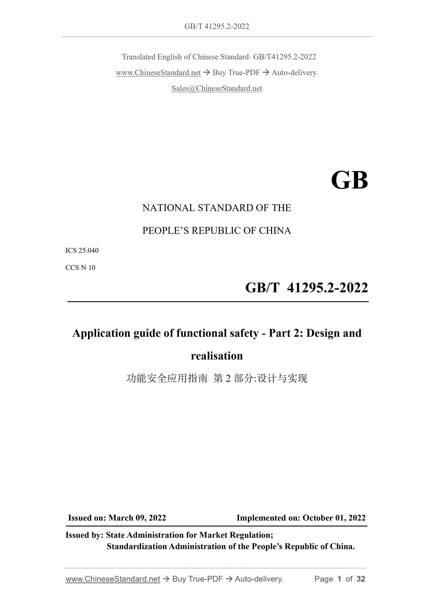
GB/T 41295.2-2022
NATIONAL STANDARD OF THE
PEOPLE’S REPUBLIC OF CHINA
ICS 25.040
CCS N 10
Application guide of functional safety - Part 2: Design and
realisation
ISSUED ON: MARCH 09, 2022
IMPLEMENTED ON: OCTOBER 01, 2022
Issued by: State Administration for Market Regulation;
Standardization Administration of the People’s Republic of China.
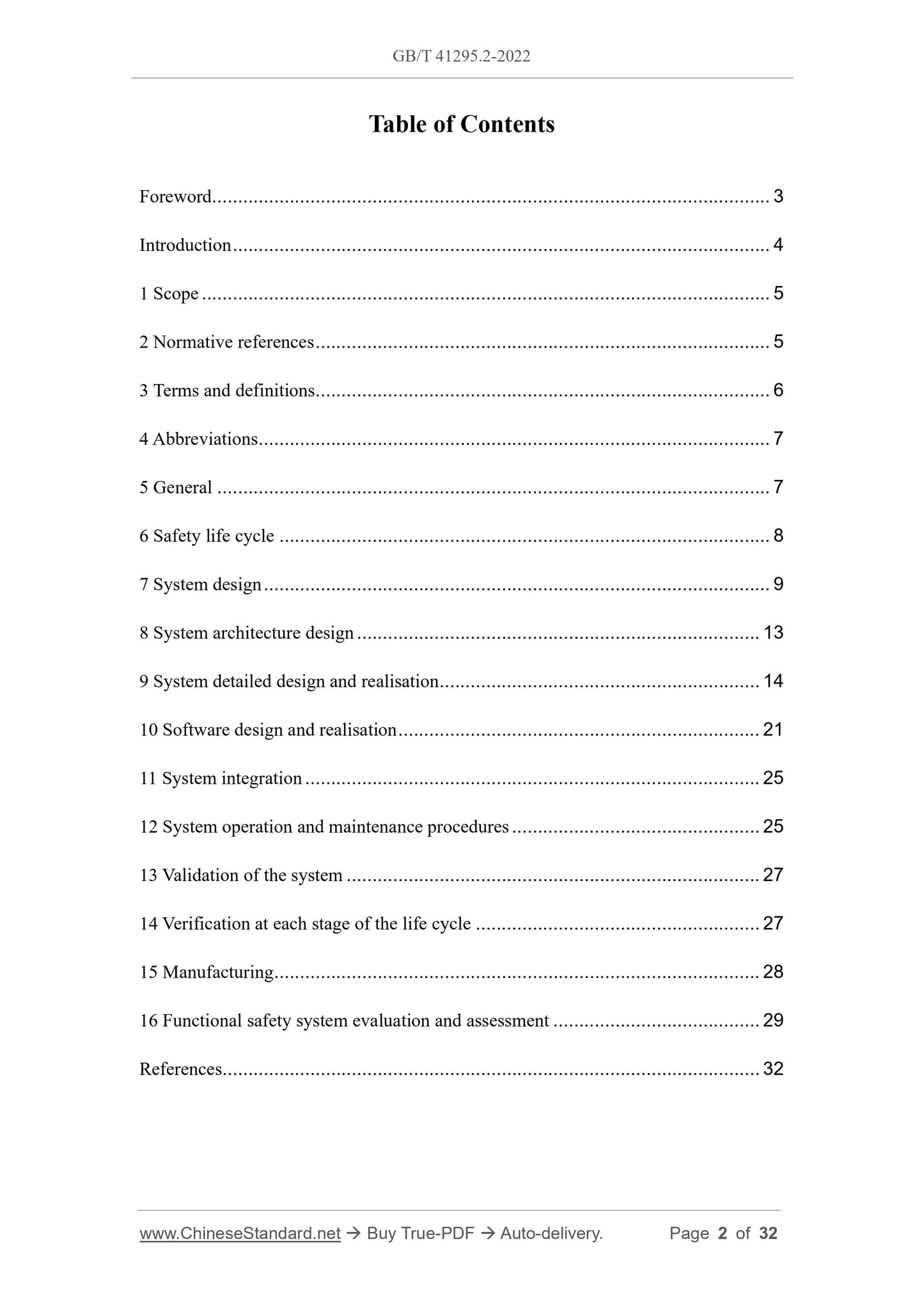
Table of Contents
Foreword ... 3 
Introduction ... 4 
1 Scope ... 5 
2 Normative references ... 5 
3 Terms and definitions... 6 
4 Abbreviations ... 7 
5 General ... 7 
6 Safety life cycle ... 8 
7 System design ... 9 
8 System architecture design ... 13 
9 System detailed design and realisation ... 14 
10 Software design and realisation ... 21 
11 System integration ... 25 
12 System operation and maintenance procedures ... 25 
13 Validation of the system ... 27 
14 Verification at each stage of the life cycle ... 27 
15 Manufacturing ... 28 
16 Functional safety system evaluation and assessment ... 29 
References ... 32 
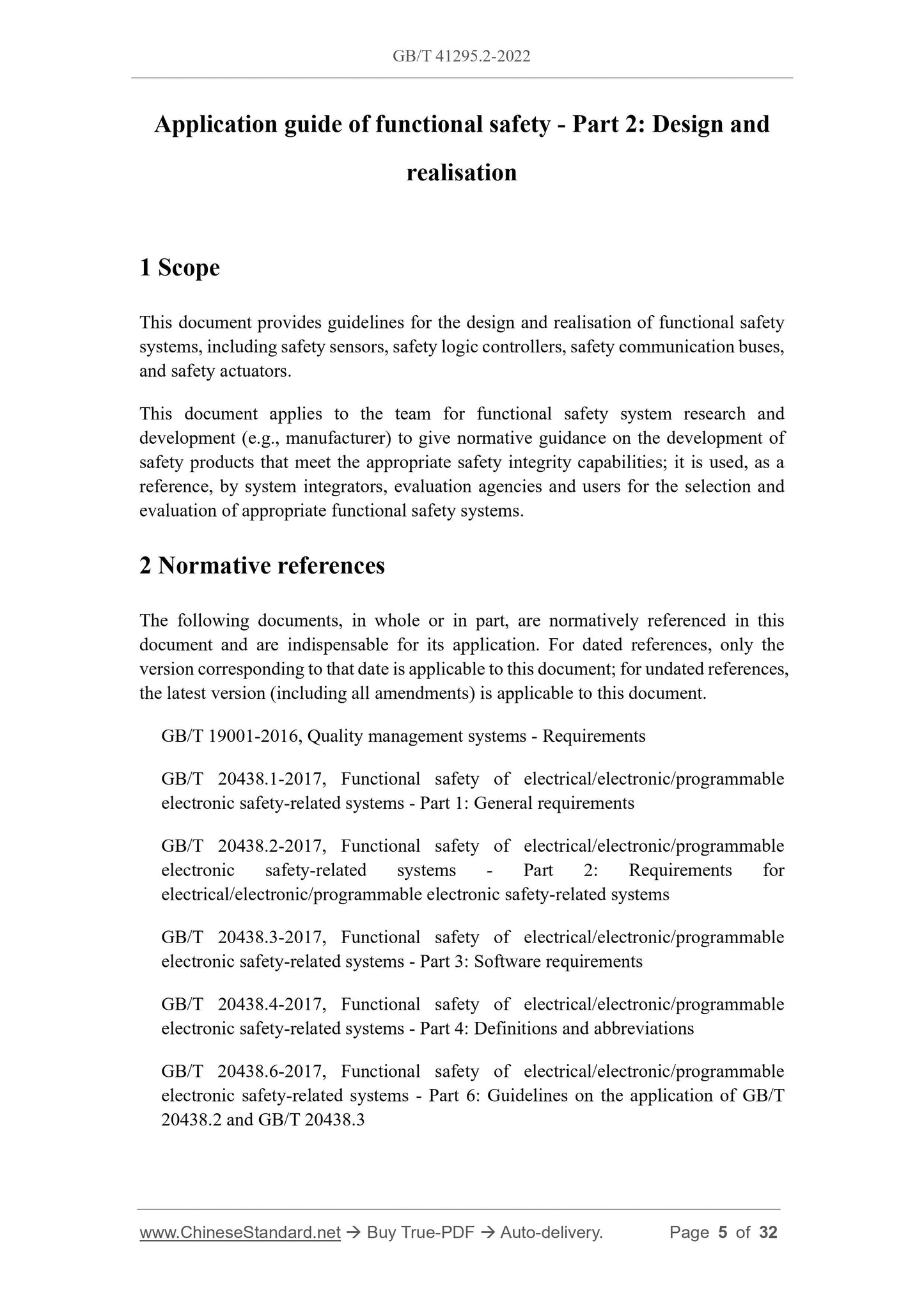
Application guide of functional safety - Part 2: Design and
realisation
1 Scope
This document provides guidelines for the design and realisation of functional safety
systems, including safety sensors, safety logic controllers, safety communication buses,
and safety actuators.
This document applies to the team for functional safety system research and
development (e.g., manufacturer) to give normative guidance on the development of
safety products that meet the appropriate safety integrity capabilities; it is used, as a
reference, by system integrators, evaluation agencies and users for the selection and
evaluation of appropriate functional safety systems.
2 Normative references
The following documents, in whole or in part, are normatively referenced in this
document and are indispensable for its application. For dated references, only the
version corresponding to that date is applicable to this document; for undated references,
the latest version (including all amendments) is applicable to this document.
GB/T 19001-2016, Quality management systems - Requirements
GB/T 20438.1-2017, Functional safety of electrical/electronic/programmable
electronic safety-related systems - Part 1: General requirements
GB/T 20438.2-2017, Functional safety of electrical/electronic/programmable
electronic safety-related systems - Part 2: Requirements for
electrical/electronic/programmable electronic safety-related systems
GB/T 20438.3-2017, Functional safety of electrical/electronic/programmable
electronic safety-related systems - Part 3: Software requirements
GB/T 20438.4-2017, Functional safety of electrical/electronic/programmable
electronic safety-related systems - Part 4: Definitions and abbreviations
GB/T 20438.6-2017, Functional safety of electrical/electronic/programmable
electronic safety-related systems - Part 6: Guidelines on the application of GB/T
20438.2 and GB/T 20438.3
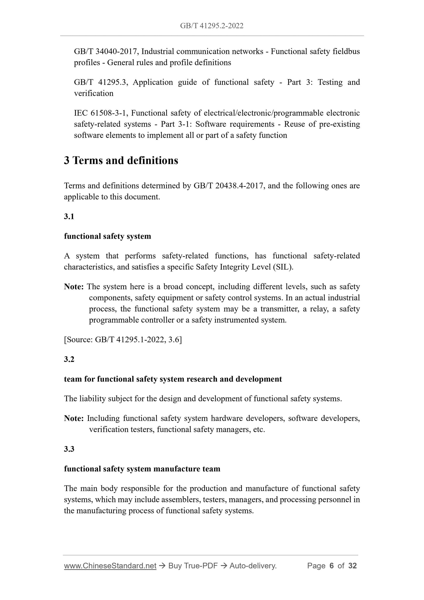
GB/T 34040-2017, Industrial communication networks - Functional safety fieldbus
profiles - General rules and profile definitions
GB/T 41295.3, Application guide of functional safety - Part 3: Testing and
verification
IEC 61508-3-1, Functional safety of electrical/electronic/programmable electronic
safety-related systems - Part 3-1: Software requirements - Reuse of pre-existing
software elements to implement all or part of a safety function
3 Terms and definitions
Terms and definitions determined by GB/T 20438.4-2017, and the following ones are
applicable to this document.
3.1
functional safety system
A system that performs safety-related functions, has functional safety-related
characteristics, and satisfies a specific Safety Integrity Level (SIL).
Note: The system here is a broad concept, including different levels, such as safety
components, safety equipment or safety control systems. In an actual industrial
process, the functional safety system may be a transmitter, a relay, a safety
programmable controller or a safety instrumented system.
[Source: GB/T 41295.1-2022, 3.6]
3.2
team for functional safety system research and development
The liability subject for the design and development of functional safety systems.
Note: Including functional safety system hardware developers, software developers,
verification testers, functional safety managers, etc.
3.3
functional safety system manufacture team
The main body responsible for the production and manufacture of functional safety
systems, which may include assemblers, testers, managers, and processing personnel in
the manufacturing process of functional safety systems.
requirements of relevant functional safety basic standards such as GB/T 20438.2-2017
and GB/T 20438.3-2017. In order to ensure that the expected SIL goals and
requirements are actually achieved, this document gives relevant application guidelines.
Note: In some fields, there are functional safety standards for specific fields; the
functional safety standards in these fields inherit the overall architecture and
core concepts of GB/T 20438.2-2017 and GB/T 20438.3-2017; therefore, when
meeting the functional safety requirements in these fields, the relevant content
of this document may be referred to.
5.2 Functional safety systems should also meet specific requirements for basic safety
(such as electrical safety), environmental adaptability, and reliability/stability in their
product standards, which are prerequisites for achieving the corresponding safety
integrity.
5.3 The production and manufacturing process of the functional safety system needs to
take into account the provisions in Chapter 15 or the functional safety standards in
related fields.
6 Safety life cycle
6.1 General principles
6.1.1 The team for functional safety system research and development needs to establish
a functional safety management system and define the safety life cycle stage in the early
stage of safety R and D.
6.1.2 The establishment of the functional safety management system and safety life
cycle needs to combine the requirements of functional safety standards and the existing
experience of the R and D team.
6.2 Application considerations
6.2.1 The functional safety management system needs to consider the requirements in
Chapter 6 of GB/T 20438.1-2017. The functional safety R and D department can refer to
the company's existing quality/safety management system to establish a functional
safety management system.
Note: The construction and implementation of systems such as GB/T 19001-2016 or
CMMI is a powerful guarantee for the realisation of functional safety
management.
6.2.2 The functional safety management system needs to include the requirements for
system or software changes, and needs to consider the requirements of 7.8 in GB/T
20438.2-2017 and 7.8 in GB/T 20438.3-2017. When a change occurs, the impact
8.1.4 For the architecture design, it is necessary to consider the applicable requirements
of 7.4 in GB/T 20438.2-2017.
8.1.5 It is necessary to consider a validation of architecture designs.
8.1.6 It is necessary to consider the integration test plan based on the architecture design
content.
8.2 Architecture design application considerations
8.2.1 The following aspects shall be considered in the architecture design to ensure
functional safety:
-- Ensure sufficient robustness of the system;
-- Ensure proper independence between different modules and avoid complex
coupling relationships and common cause failures;
-- Ensure that non-safety-related modules do not negatively affect safety-related
modules.
8.2.2 It is necessary to have a normative description of the static characteristics of the
architecture design (for example, a block diagram of the architecture), and describe
each module and the interfaces between modules that make up the system architecture.
8.2.3 The architecture design should avoid describing the realisation details inside each
module, which shall be the content of the subsequent detailed design.
8.2.4 The multi-channel MooN voting structure can be considered to achieve high
security or high availability design. The multi-channel voting can be realized at
different levels, such as the device level, module level, board level, and even chip level.
8.2.5 It is necessary to clearly distinguish the difference between the MooN voting
structure and the standby structure. Generally, the standby structure is used to improve
availability rather than safety.
8.2.6 After completing the architecture design verification, it is necessary to develop an
integration test plan, which includes a test strategy for all architecture features and
interface features.
9 System detailed design and realisation
9.1 General principles
9.1.1 The basic requirements for the design and development of functional safety
systems need to consider the requirements in 7.4, Appendix A and B.2 of GB/T 20438.2-
2017.
9.1.2 It is necessary to consider the preparation of relevant documents for hardware
detailed design, and realize the hardware circuit based on the detailed design.
9.2 Application considerations
9.2.1 Requirements for random hardware failures
9.2.1.1 The final random hardware failures of the functional safety system is less than
or equal to the target specified in Chapter 7 (PFDavg or PFH value), and it is proved
through reasonable modeling and calculation that the target can be achieved.
9.2.1.2 The scope of random hardware failure estimation is for all safety-related parts
of a functional safety system.
9.2.1.3 It is necessary to consider the estimation of PFDavg or PFH in accordance with
Appendix B of GB/T 20438.6-2017. If this method is adopted, ensure that the actual
system to be analyzed meets all the specified assumptions. If other methods are used,
there should be a rationality proof in line with mathematical logic.
Note: Some literatures give very simplified formulas. Be more careful about the
application of simplified formulas, because the simplified conditions may not
match the current actual project requirements, which will lead to errors in the
simplified formulas.
9.2.1.4 Consideration should be given to the use of an appropriate component failure
rate/failure model database as input to the calculation, which can be derived from:
-- International standards or national standards, industry standards, such as ISO
13849-1;
-- Commercial databases widely recognized in the field;
-- On-site feedback data with a special collection system, which shall ensure a
statistical confidence ≥ 70%.
9.2.1.5 A single source failure rate/failure mode database should be used for
calculations of the same system. Data from multiple sources should only be used if it
can be demonstrated that the data were obtained under common conditions.
9.2.1.6 Some calculation input parameters, such as inspection and test cycle (T1), mean
time to restore (MTTR) and mean repair time (MRT), are not determined by the
functional safety system R and D and design unit, therefore, it is necessary to preset a
value to participate in the calculation based on the expected application of the product.
The rationality of the value needs to be analyzed and demonstrated specifically. These
preset values should be clearly stated in the subsequent product manual of the functional
safety system.
9.2.2.4 Care should be taken to distinguish between safe failures and no-effect failures;
no-effect failures cannot be included in safe failures.
9.2.2.5 Based on the conclusions of hardware failure analysis, the existing safety design
needs to be reviewed to ensure that all critical failures are effectively controlled or
avoided.
9.2.2.6 It is necessary to carefully judge the validity of each diagnostic function. Invalid
diagnosis cannot classify the corresponding failure as diagnosable. Invalid diagnosis
includes but is not limited to:
-- The diagnostic test interval is too long to meet the requirements of the process
safety time;
-- If a multi-channel design is used, pure inter-channel voting cannot be used as a
diagnostic measure for device failure in a single channel;
-- There is no proper fault response or alarm after a fault is diagnosed.
9.2.3 Determination of diagnostic coverage
The coverage rate of each diagnostic function needs to be carefully judged, and it is
generally judged according to the following considerations.
-- For simple components, if the diagnostic test can diagnose one of its failure modes,
the diagnostic coverage of this failure mode of the device is 100%, otherwise it is
0%. Examples of simple devices: resistors, capacitors, transistors, diodes,
optocoupler, etc.
-- For complex devices, in principle, it is based on the requirements of A.1 ~ A.14 in
GB/T 20438.2-2017. If there is a statement of higher diagnostic coverage or if a
technique not specified in Appendix A of GB/T 20438.2-2017 is used, use the test
method to prove the authenticity of the achieved diagnostic coverage. Examples
of complex components: central processing unit (CPU), analog-to-digital
conversion (ADC) chips, memory cells, etc.
-- For the same device or module, two or more diagnostic methods can be used to
diagnose the same failure mode, which can achieve higher diagnostic coverage
than that specified in Appendix A of GB/T 20438.2-2017. But these different
methods must be independent, and there is no possibility of common cause failure.
9.2.4 Diagnostic functions and diagnostic coverage (DC)
9.2.4.1 For the self-diagnostic measures for the sufficiency of functional safety system
design, the determination of whether the design is sufficient shall be considered as
follows:
-- The system follows the single failure principle;
-- PFDavg/PFH meets the requirements of the target failure;
-- SFF satisfies the requirements of architectural constraints.
Note: Sufficient diagnostic functions can be more conducive to the realisation of the
above requirements, but it does not rely solely on the diagnostic functions. For
example, the failure rate and the length of the inspectio...
View full details