Skip to product information
1 of 9

PayPal, credit cards. Download editable-PDF and invoice in 1 second!

GB/T 41120-2021 English PDF (GBT41120-2021)

GB/T 41120-2021 English PDF (GBT41120-2021)

Regular price $230.00 USD
Regular price Sale price $230.00 USD
Sale Sold out
Shipping calculated at checkout.
Delivery: 3 seconds. Download true-PDF + Invoice.
Get QUOTATION in 1-minute: Click GB/T 41120-2021
Historical versions: GB/T 41120-2021
Preview True-PDF (Reload/Scroll if blank)

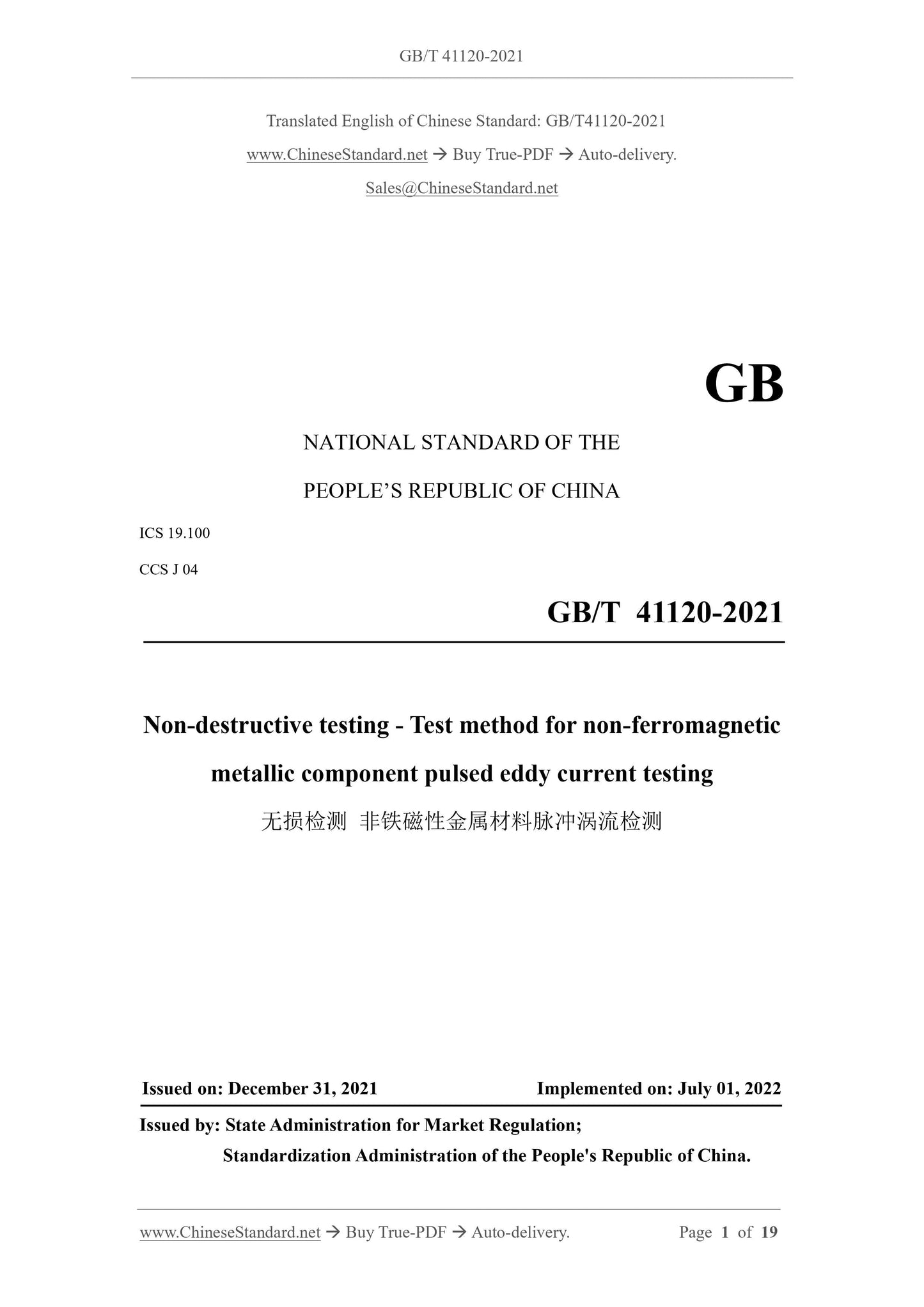
GB/T 41120-2021: Non-destructive testing -- Test method for non-ferromagnetic metallic component pulsed eddy current testing
GB/T 41120-2021
NATIONAL STANDARD OF THE
PEOPLE’S REPUBLIC OF CHINA
ICS 19.100
CCS J 04
Non-destructive testing - Test method for non-ferromagnetic
metallic component pulsed eddy current testing
ISSUED ON: DECEMBER 31, 2021
IMPLEMENTED ON: JULY 01, 2022
Issued by: State Administration for Market Regulation;
Standardization Administration of the People's Republic of China.
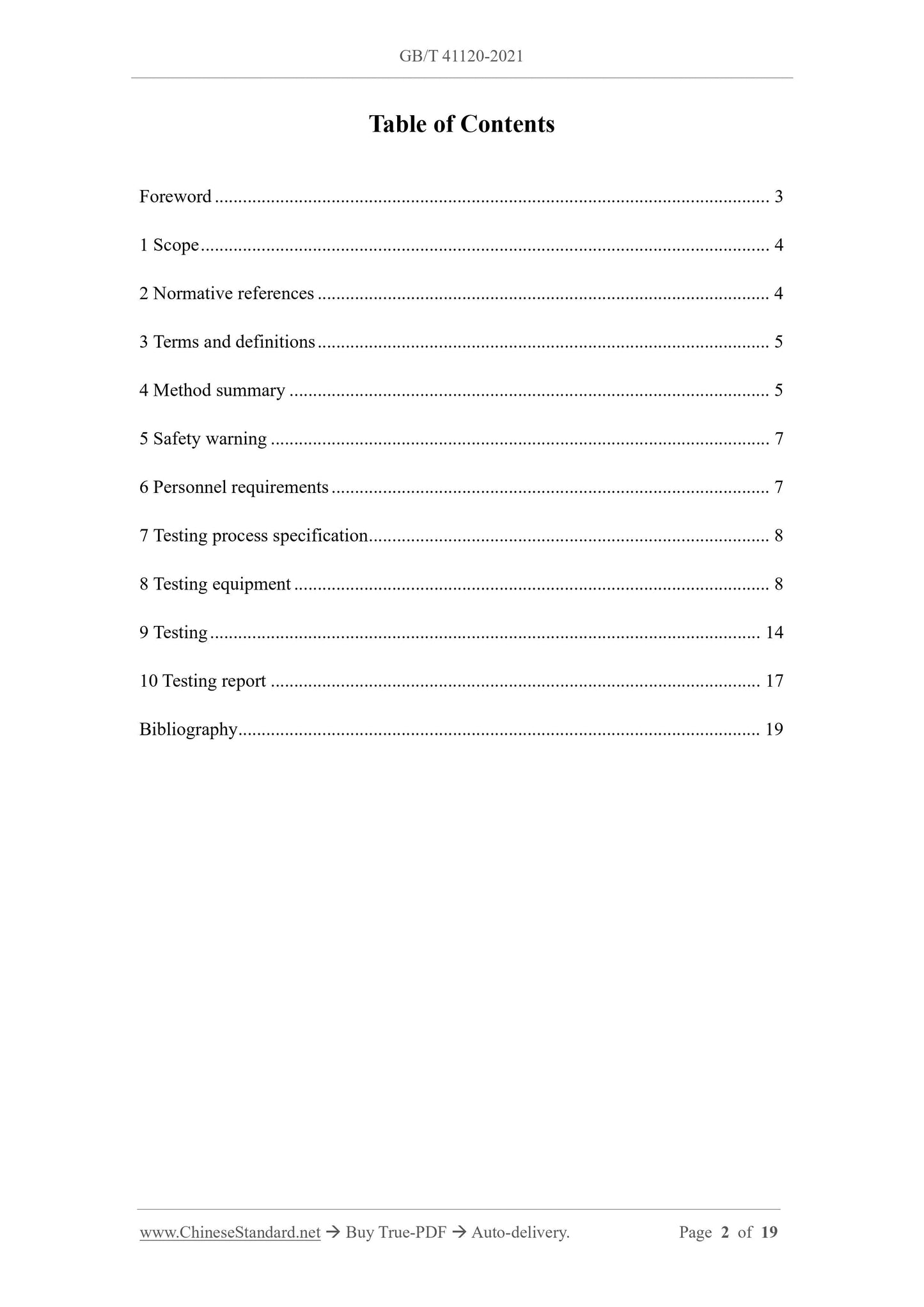
Table of Contents
Foreword ... 3
1 Scope ... 4
2 Normative references ... 4
3 Terms and definitions ... 5
4 Method summary ... 5
5 Safety warning ... 7
6 Personnel requirements ... 7
7 Testing process specification ... 8
8 Testing equipment ... 8
9 Testing ... 14
10 Testing report ... 17
Bibliography ... 19
Non-destructive testing - Test method for non-ferromagnetic
metallic component pulsed eddy current testing
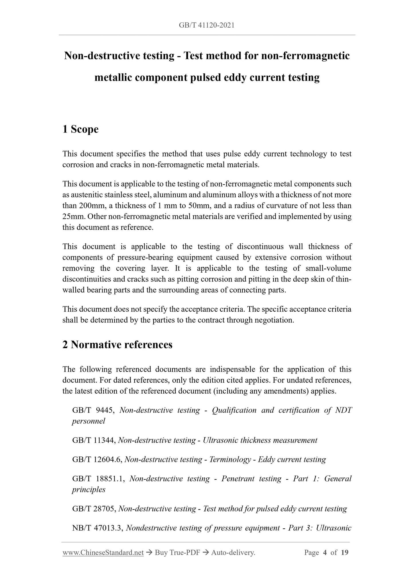
1 Scope
This document specifies the method that uses pulse eddy current technology to test
corrosion and cracks in non-ferromagnetic metal materials.
This document is applicable to the testing of non-ferromagnetic metal components such
as austenitic stainless steel, aluminum and aluminum alloys with a thickness of not more
than 200mm, a thickness of 1 mm to 50mm, and a radius of curvature of not less than
25mm. Other non-ferromagnetic metal materials are verified and implemented by using
this document as reference.
This document is applicable to the testing of discontinuous wall thickness of
components of pressure-bearing equipment caused by extensive corrosion without
removing the covering layer. It is applicable to the testing of small-volume
discontinuities and cracks such as pitting corrosion and pitting in the deep skin of thin-
walled bearing parts and the surrounding areas of connecting parts.
This document does not specify the acceptance criteria. The specific acceptance criteria
shall be determined by the parties to the contract through negotiation.
2 Normative references
The following referenced documents are indispensable for the application of this
document. For dated references, only the edition cited applies. For undated references,
the latest edition of the referenced document (including any amendments) applies.
GB/T 9445, Non-destructive testing - Qualification and certification of NDT
personnel
GB/T 11344, Non-destructive testing - Ultrasonic thickness measurement
GB/T 12604.6, Non-destructive testing - Terminology - Eddy current testing
GB/T 18851.1, Non-destructive testing - Penetrant testing - Part 1: General
principles
GB/T 28705, Non-destructive testing - Test method for pulsed eddy current testing
NB/T 47013.3, Nondestructive testing of pressure equipment - Part 3: Ultrasonic
testing
3 Terms and definitions
For the purposes of this document, the terms and definitions defined in GB/T 12604.6,
GB/T 28705 as well as the followings apply.
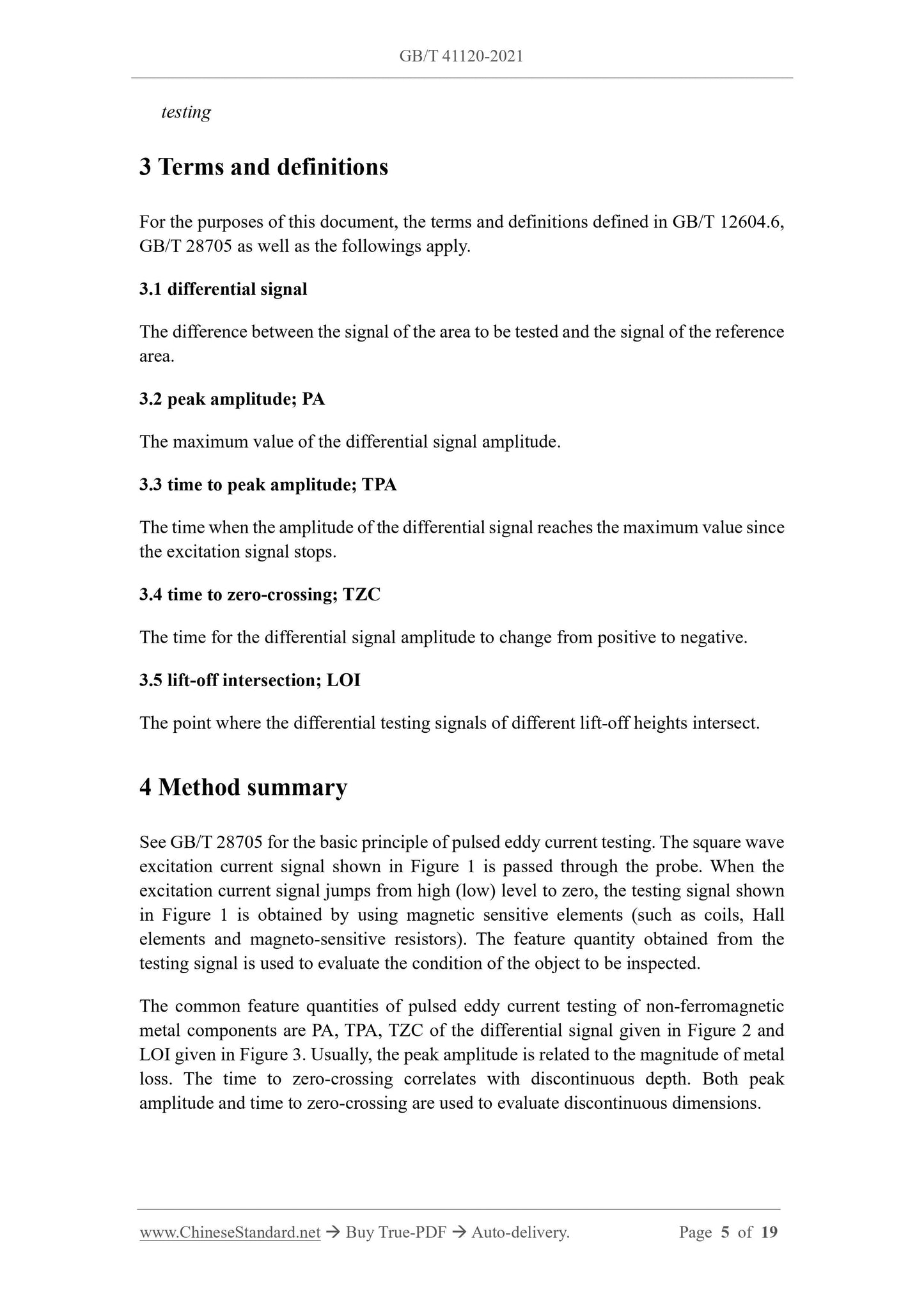
3.1 differential signal
The difference between the signal of the area to be tested and the signal of the reference
area.
3.2 peak amplitude; PA
The maximum value of the differential signal amplitude.
3.3 time to peak amplitude; TPA
The time when the amplitude of the differential signal reaches the maximum value since
the excitation signal stops.
3.4 time to zero-crossing; TZC
The time for the differential signal amplitude to change from positive to negative.
3.5 lift-off intersection; LOI
The point where the differential testing signals of different lift-off heights intersect.
4 Method summary
See GB/T 28705 for the basic principle of pulsed eddy current testing. The square wave
excitation current signal shown in Figure 1 is passed through the probe. When the
excitation current signal jumps from high (low) level to zero, the testing signal shown
in Figure 1 is obtained by using magnetic sensitive elements (such as coils, Hall
elements and magneto-sensitive resistors). The feature quantity obtained from the
testing signal is used to evaluate the condition of the object to be inspected.
The common feature quantities of pulsed eddy current testing of non-ferromagnetic
metal components are PA, TPA, TZC of the differential signal given in Figure 2 and
LOI given in Figure 3. Usually, the peak amplitude is related to the magnitude of metal
loss. The time to zero-crossing correlates with discontinuous depth. Both peak
amplitude and time to zero-crossing are used to evaluate discontinuous dimensions.
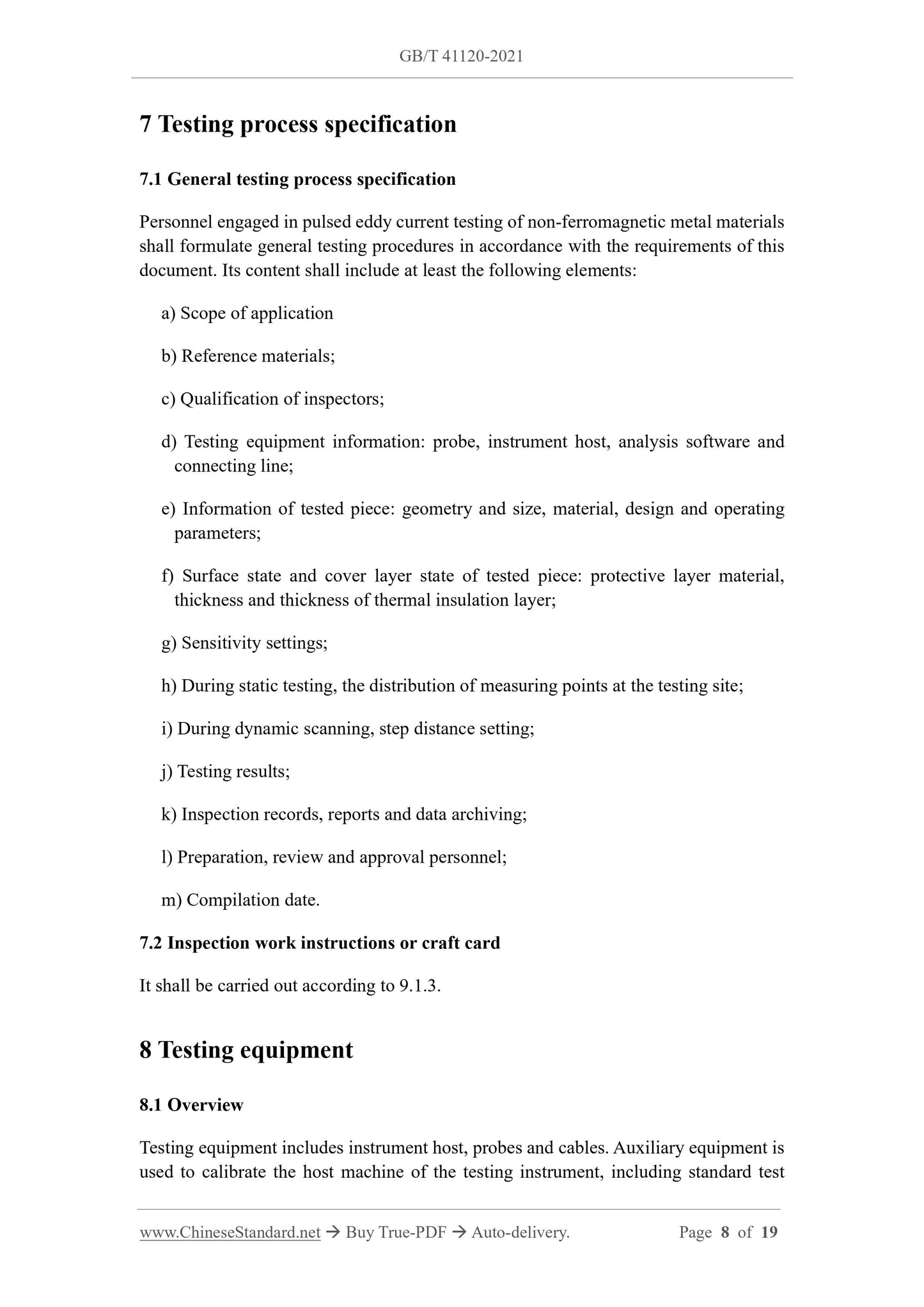
7 Testing process specification
7.1 General testing process specification
Personnel engaged in pulsed eddy current testing of non-ferromagnetic metal materials
shall formulate general testing procedures in accordance with the requirements of this
document. Its content shall include at least the following elements:
a) Scope of application
b) Reference materials;
c) Qualification of inspectors;
d) Testing equipment information: probe, instrument host, analysis software and
connecting line;
e) Information of tested piece: geometry and size, material, design and operating
parameters;
f) Surface state and cover layer state of tested piece: protective layer material,
thickness and thickness of thermal insulation layer;
g) Sensitivity settings;
h) During static testing, the distribution of measuring points at the testing site;
i) During dynamic scanning, step distance setting;
j) Testing results;
k) Inspection records, reports and data archiving;
l) Preparation, review and approval personnel;
m) Compilation date.
7.2 Inspection work instructions or craft card
It shall be carried out according to 9.1.3.
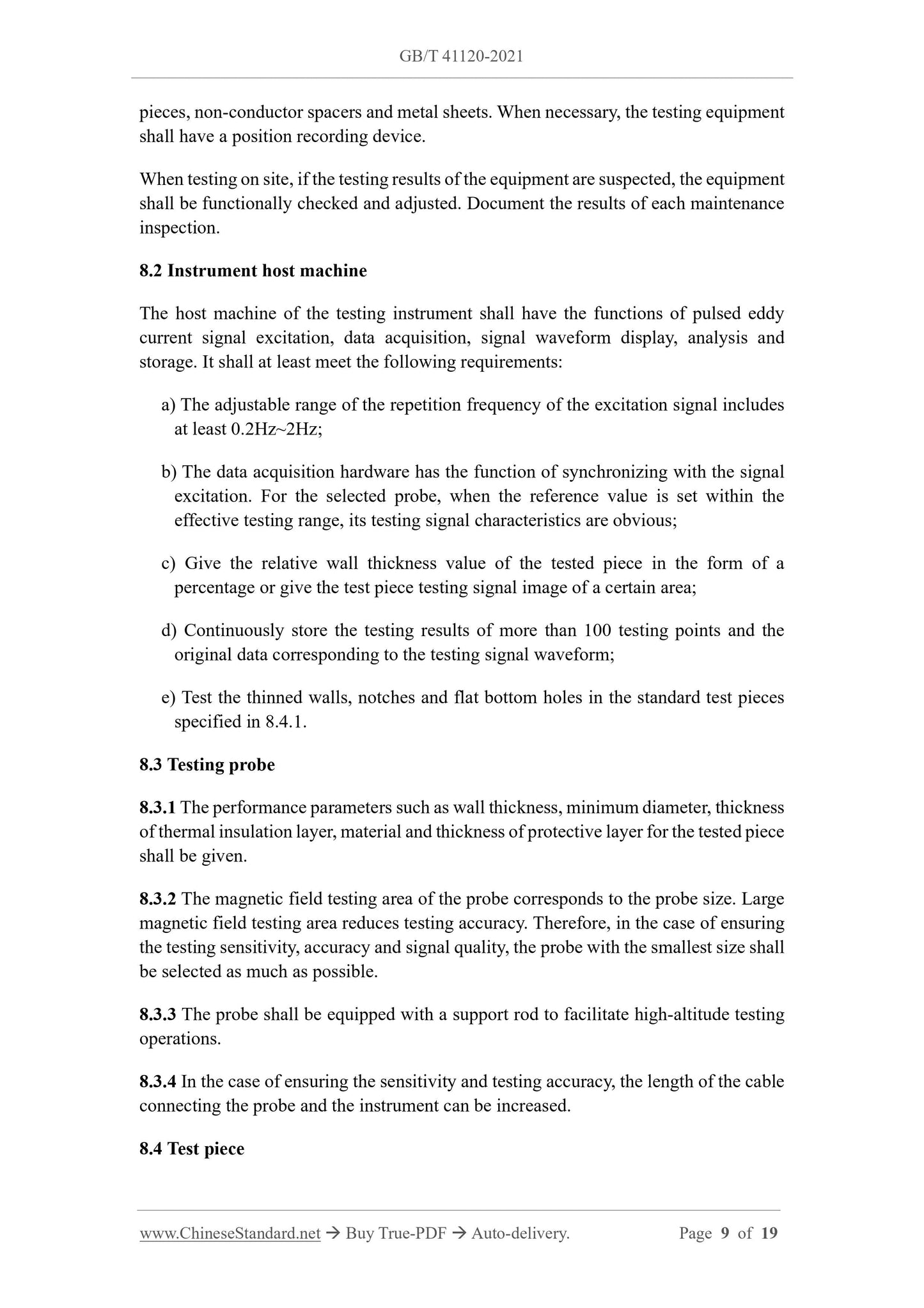
8 Testing equipment
8.1 Overview
Testing equipment includes instrument host, probes and cables. Auxiliary equipment is
used to calibrate the host machine of the testing instrument, including standard test
pieces, non-conductor spacers and metal sheets. When necessary, the testing equipment
shall have a position recording device.
When testing on site, if the testing results of the equipment are suspected, the equipment
shall be functionally checked and adjusted. Document the results of each maintenance
inspection.
8.2 Instrument host machine
The host machine of the testing instrument shall have the functions of pulsed eddy
current signal excitation, data acquisition, signal waveform display, analysis and
storage. It shall at least meet the following requirements:
a) The adjustable range of the repetition frequency of the excitation signal includes
at least 0.2Hz~2Hz;
b) The data acquisition hardware has the function of synchronizing with the signal
excitation. For the selected probe, when the reference value is set within the
effective testing range, its testing signal characteristics are obvious;
c) Give the relative wall thickness value of the tested piece in the form of a
percentage or give the test piece testing signal image of a certain area;
d) Continuously store the testing results of more than 100 testing points and the
original data corresponding to the testing signal waveform;
e) Test the thinned walls, notches and flat bottom holes in the standard test pieces
specified in 8.4.1.
8.3 Testing probe
8.3.1 The performance parameters such as wall thickness, minimum diameter, thickness
of thermal insulation layer, material and thickness of protective layer for the tested piece
shall be given.
8.3.2 The magnetic field testing area of the probe corresponds to the probe size. Large
magnetic field testing area reduces testing accuracy. Therefore, in the case of ensuring
the testing se...
View full details