Skip to product information
1 of 8

PayPal, credit cards. Download editable-PDF & invoice in 1 second!

GB/T 40821-2021 English PDF (GBT40821-2021)

GB/T 40821-2021 English PDF (GBT40821-2021)

Regular price $290.00 USD
Regular price Sale price $290.00 USD
Sale Sold out
Shipping calculated at checkout.
Quotation: In 1-minute, 24-hr self-service. Click here GB/T 40821-2021 to get it for Purchase Approval, Bank TT...

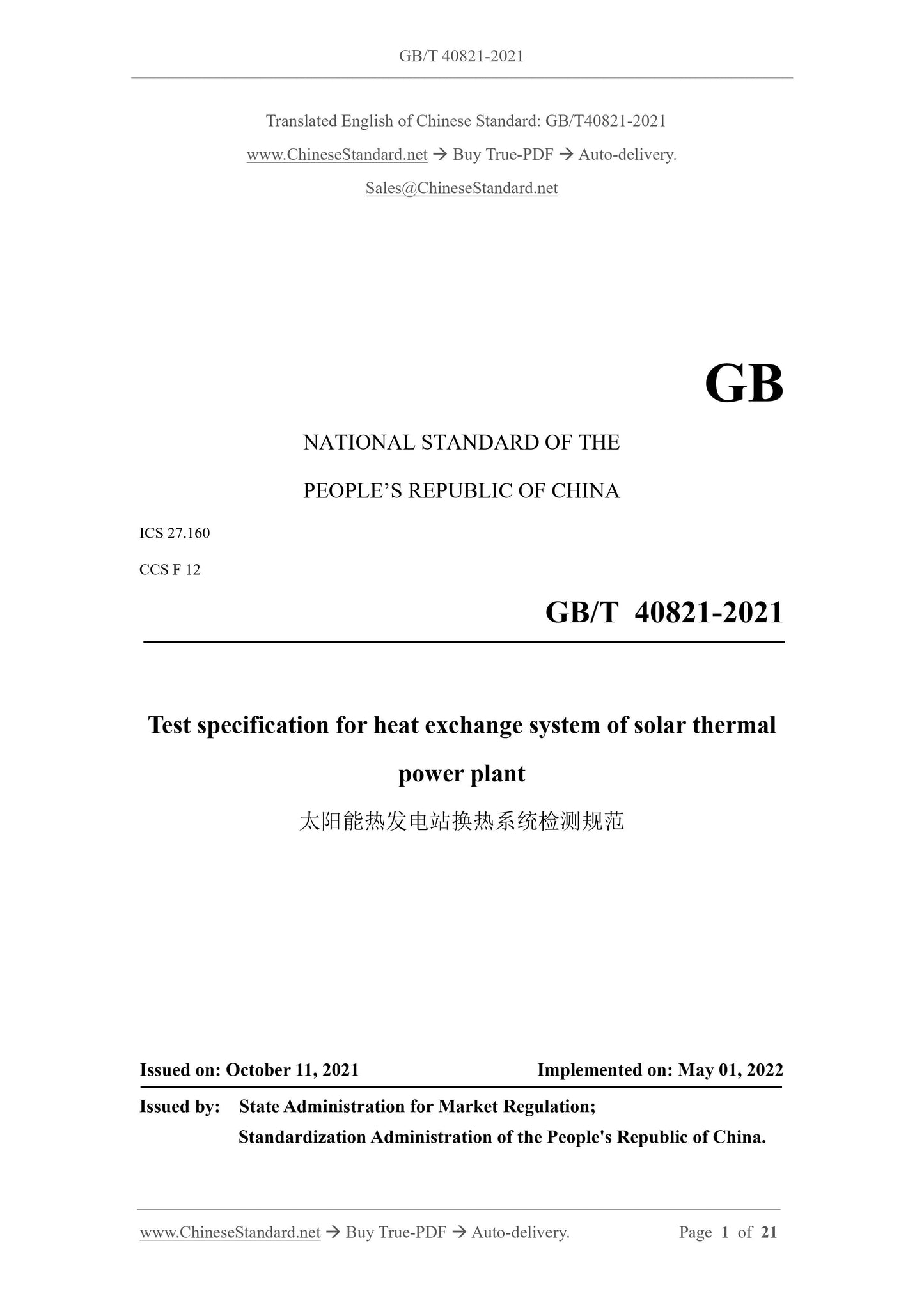
GB/T 40821-2021: Test specification for heat exchange system of solar thermal power plant

This document specifies the general method for performance test of heat exchange system of solar thermal power plant. This document is applicable to the steam generation system with heat transfer oil or molten salt as the heat transfer medium, and the oil-salt heat exchange system with molten salt as the heat storage medium.
GB/T 40821-2021
NATIONAL STANDARD OF THE
PEOPLE’S REPUBLIC OF CHINA
ICS 27.160
CCS F 12
Test specification for heat exchange system of solar thermal
power plant
ISSUED ON: OCTOBER 11, 2021
IMPLEMENTED ON: MAY 01, 2022
Issued by: State Administration for Market Regulation;
Standardization Administration of the People's Republic of China.
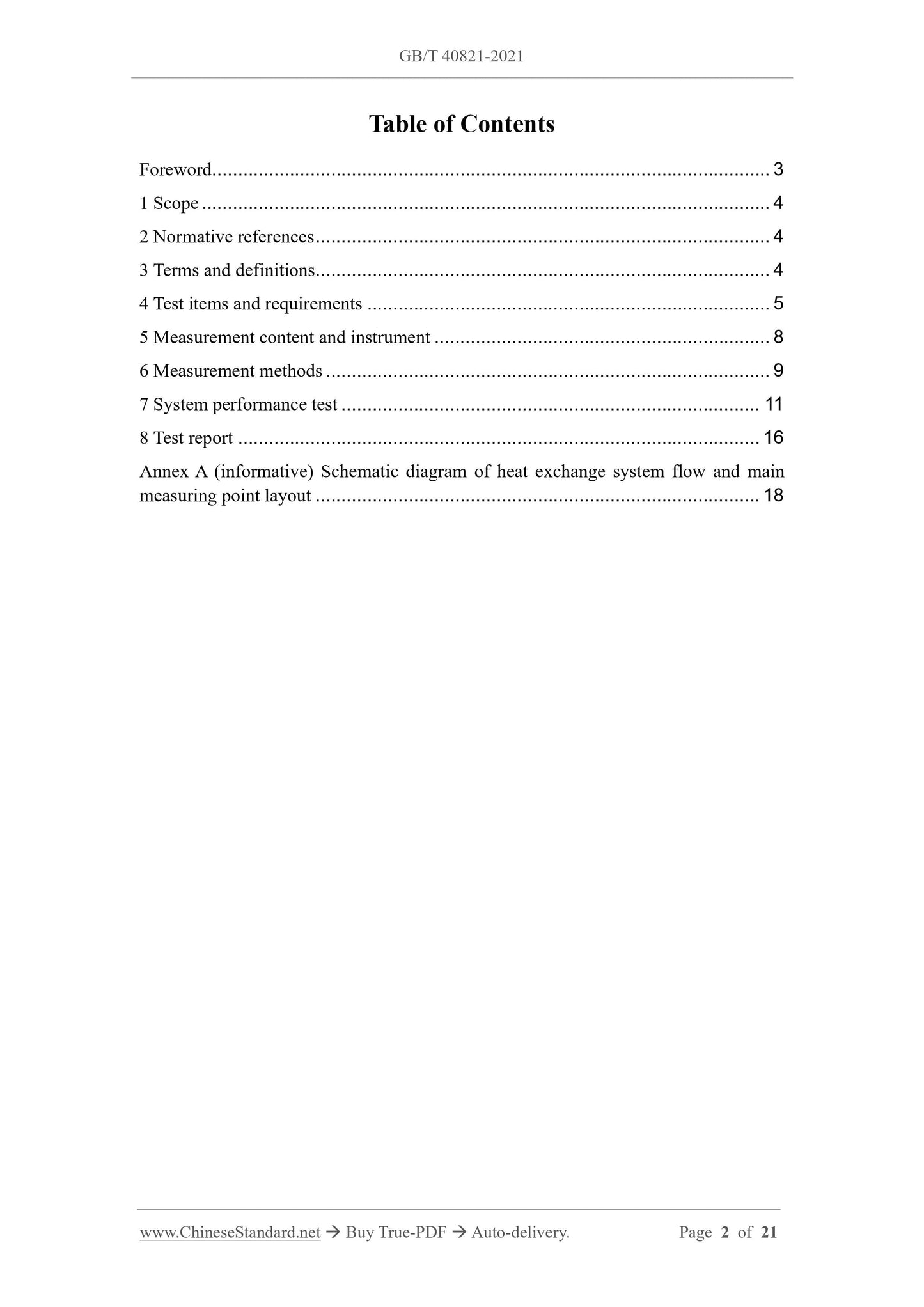
Table of Contents
Foreword ... 3
1 Scope ... 4
2 Normative references ... 4
3 Terms and definitions... 4
4 Test items and requirements ... 5
5 Measurement content and instrument ... 8
6 Measurement methods ... 9
7 System performance test ... 11
8 Test report ... 16
Annex A (informative) Schematic diagram of heat exchange system flow and main measuring point layout ... 18
Test specification for heat exchange system of solar thermal
power plant
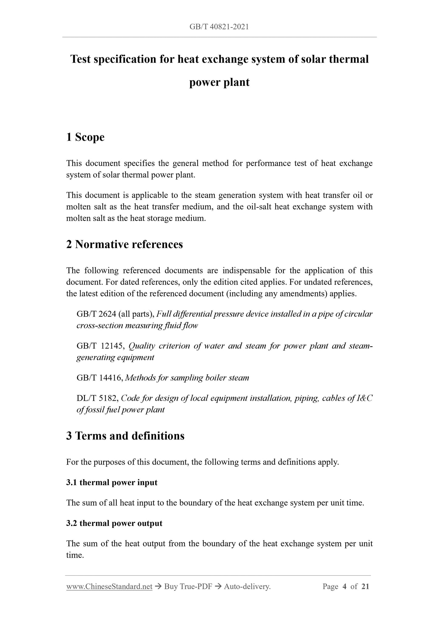
1 Scope
This document specifies the general method for performance test of heat exchange system of solar thermal power plant.
This document is applicable to the steam generation system with heat transfer oil or molten salt as the heat transfer medium, and the oil-salt heat exchange system with molten salt as the heat storage medium.
2 Normative references
The following referenced documents are indispensable for the application of this document. For dated references, only the edition cited applies. For undated references, the latest edition of the referenced document (including any amendments) applies. GB/T 2624 (all parts), Full differential pressure device installed in a pipe of circular cross-section measuring fluid flow
GB/T 12145, Quality criterion of water and steam for power plant and steam- generating equipment
GB/T 14416, Methods for sampling boiler steam
DL/T 5182, Code for design of local equipment installation, piping, cables of I&C of fossil fuel power plant
3 Terms and definitions
For the purposes of this document, the following terms and definitions apply. 3.1 thermal power input
The sum of all heat input to the boundary of the heat exchange system per unit time. 3.2 thermal power output
The sum of the heat output from the boundary of the heat exchange system per unit time.
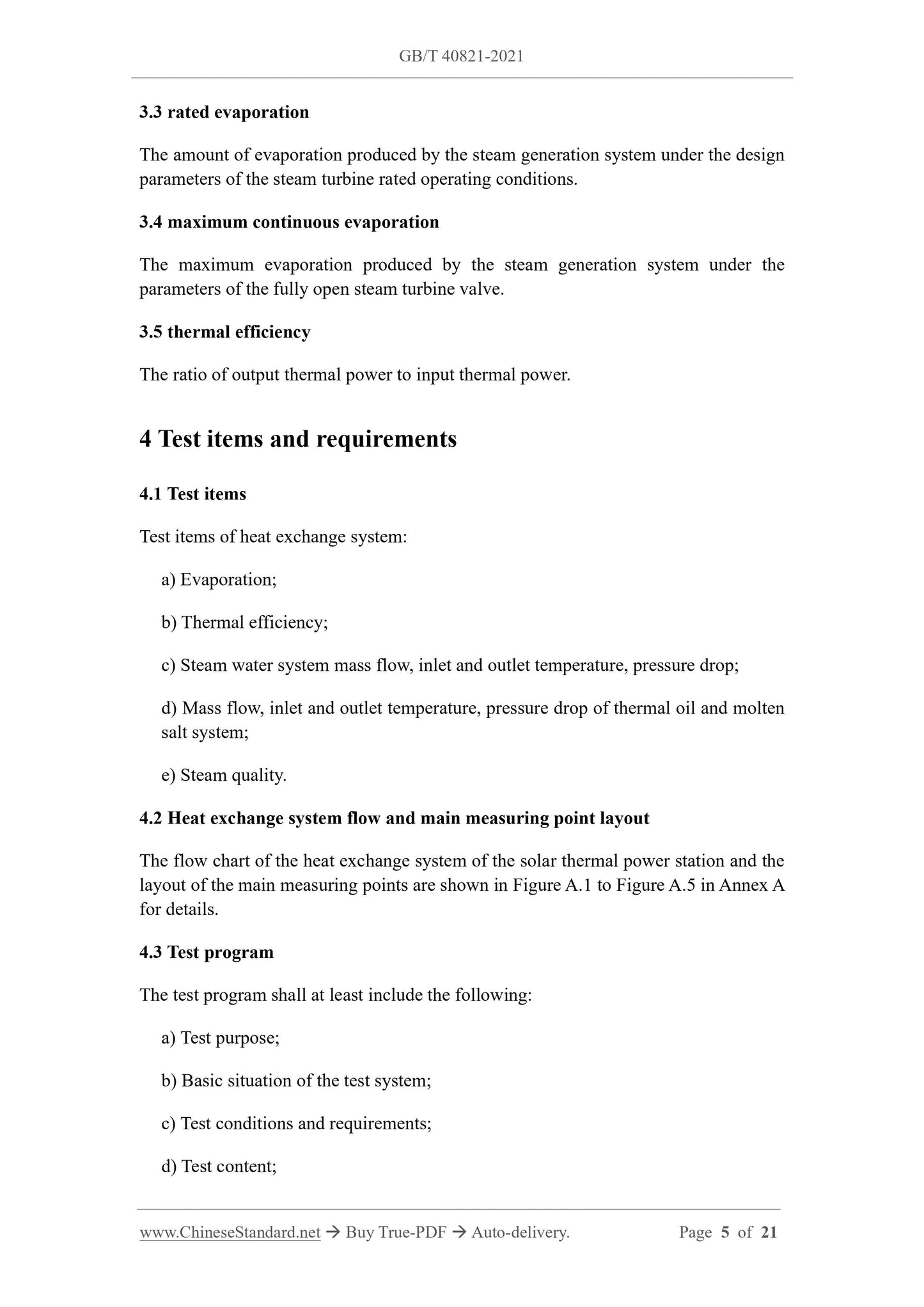
3.3 rated evaporation
The amount of evaporation produced by the steam generation system under the design parameters of the steam turbine rated operating conditions.
3.4 maximum continuous evaporation
The maximum evaporation produced by the steam generation system under the parameters of the fully open steam turbine valve.
3.5 thermal efficiency
The ratio of output thermal power to input thermal power.
4 Test items and requirements
4.1 Test items
Test items of heat exchange system:
a) Evaporation;
b) Thermal efficiency;
c) Steam water system mass flow, inlet and outlet temperature, pressure drop; d) Mass flow, inlet and outlet temperature, pressure drop of thermal oil and molten salt system;
e) Steam quality.
4.2 Heat exchange system flow and main measuring point layout
The flow chart of the heat exchange system of the solar thermal power station and the layout of the main measuring points are shown in Figure A.1 to Figure A.5 in Annex A for details.
4.3 Test program
The test program shall at least include the following:
a) Test purpose;
b) Basic situation of the test system;
c) Test conditions and requirements;
d) Test content;
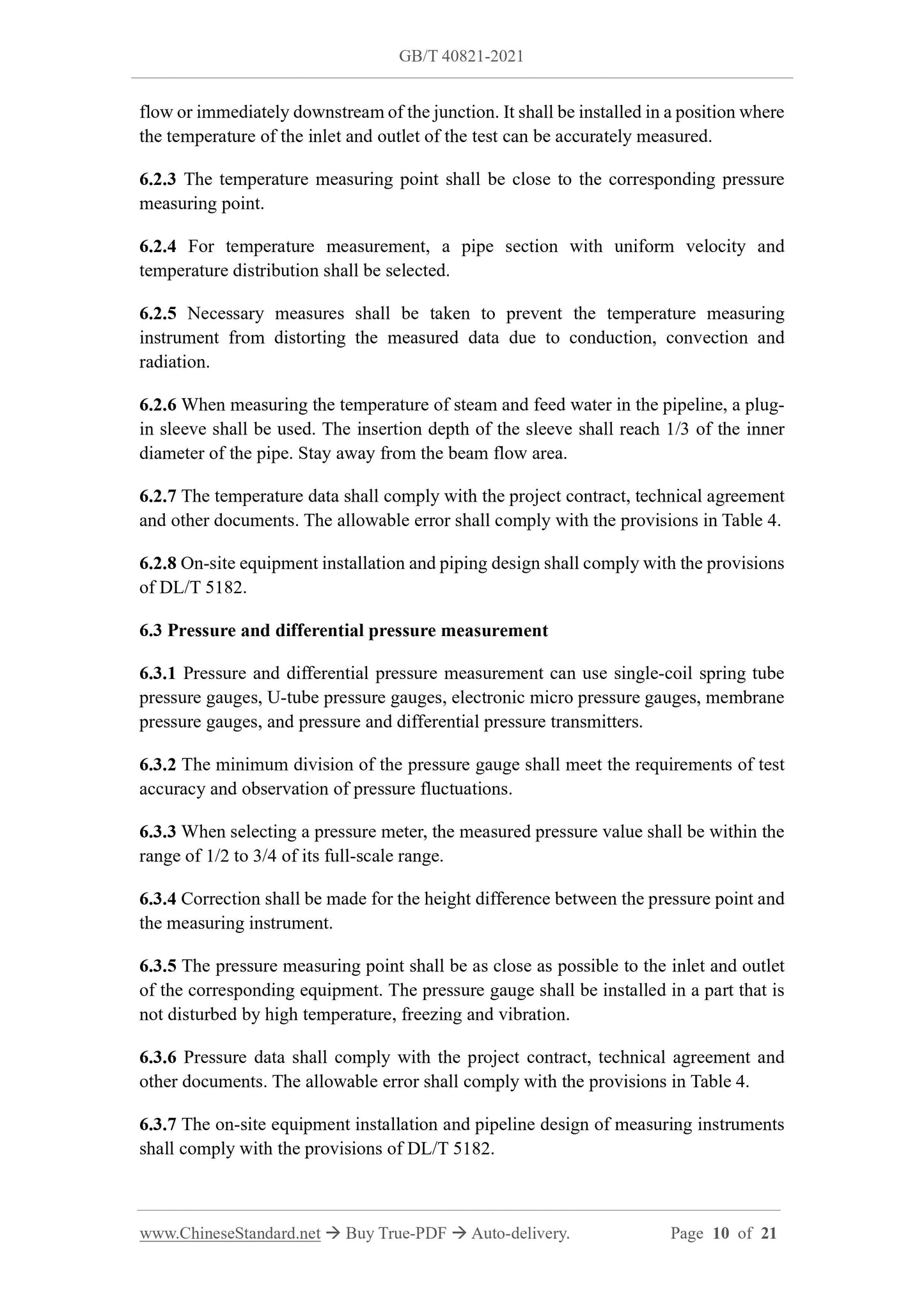
flow or immediately downstream of the junction. It shall be installed in a position where the temperature of the inlet and outlet of the test can be accurately measured. 6.2.3 The temperature measuring point shall be close to the corresponding pressure measuring point.
6.2.4 For temperature measurement, a pipe section with uniform velocity and temperature distribution shall be selected.
6.2.5 Necessary measures shall be taken to prevent the temperature measuring instrument from distorting the measured data due to conduction, convection and radiation.
6.2.6 When measuring the temperature of steam and feed water in the pipeline, a plug- in sleeve shall be used. The insertion depth of the sleeve shall reach 1/3 of the inner diameter of the pipe. Stay away from the beam flow area.
6.2.7 The temperature data shall comply with the project contract, technical agreement and other documents. The allowable error shall comply with the provisions in Table 4. 6.2.8 On-site equipment installation and piping design shall comply with the provisions of DL/T 5182.
6.3 Pressure and differential pressure measurement
6.3.1 Pressure and differential pressure measurement can use single-coil spring tube pressure gauges, U-tube pressure gauges, electronic micro pressure gauges, membrane pressure gauges, and pressure and differential pressure transmitters.
6.3.2 The minimum division of the pressure gauge shall meet the requirements of test accuracy and observation of pressure fluctuations.
6.3.3 When selecting a pressure meter, the measured pressure value shall be within the range of 1/2 to 3/4 of its full-scale range.
6.3.4 Correction shall be made for the height difference between the pressure point and the measuring instrument.
6.3.5 The pressure measuring point shall be as close as possible to the inlet and outlet of the corresponding equipment. The pressure gauge shall be installed in a part that is not disturbed by high temperature, freezing and vibration.
6.3.6 Pressure data shall comply with the project contract, technical agreement and other documents. The allowable error shall comply with the provisions in Table 4. 6.3.7 The on-site equipment installation and pipeline design of measuring instruments shall comply with the provisions of DL/T 5182.
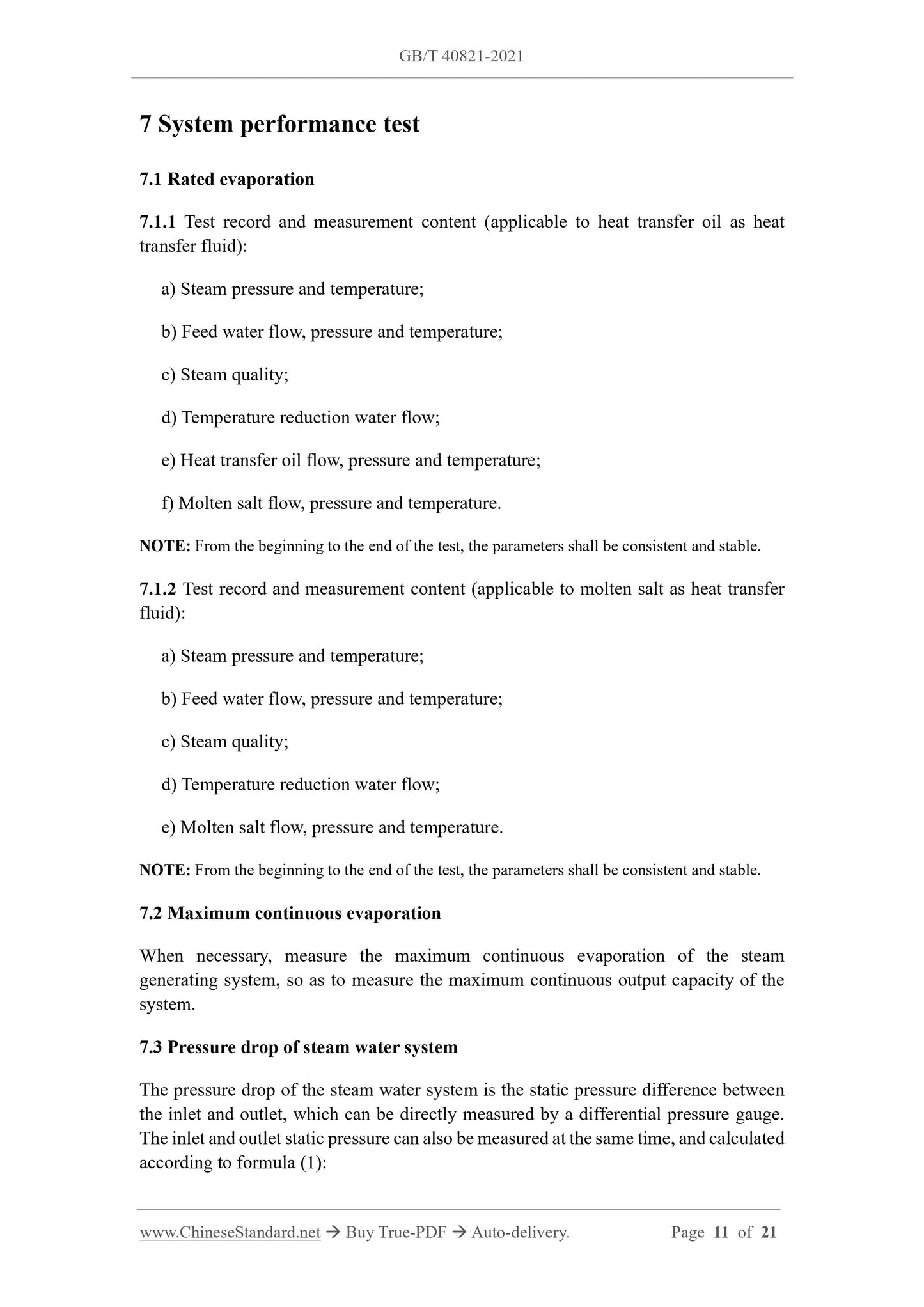
7 System performance test
7.1 Rated evaporation
7.1.1 Test record and measurement content (applicable to heat transfer oil as heat transfer fluid):
a) Steam pressure and temperature;
b) Feed water flow, pressure and temperature;
c) Steam quality;
d) Temperature reduction water flow;
e) Heat transfer oil flow, pressure and temperature;
f) Molten salt flow, pressure and temperature.
NOTE: From the beginning to the end of the test, the parameters shall be consistent and stable. 7.1.2 Test record and measurement content (applicable to molten salt as heat transfer fluid):
a) Steam pressure and temperature;
b) Feed water flow, pressure and temperature;
c) Steam quality;
d) Temperature reduction water flow;
e) Molten salt flow, pressure and temperature.
NOTE: From the beginning to the end of the test, the parameters shall be consistent and stable. 7.2 Maximum continuous evaporation
When necessary, measure the maximum continuous evaporation of the steam generating system, so as to measure the maximum continuous output capacity of the system.
7.3 Pressure drop of steam water system
The pressure drop of the steam water system is the static pressure difference between the inlet and outlet, which can be directly measured by a differential pressure gauge. The inlet and outlet static pressure can also be measured at the same time, and calculated according to formula (1):
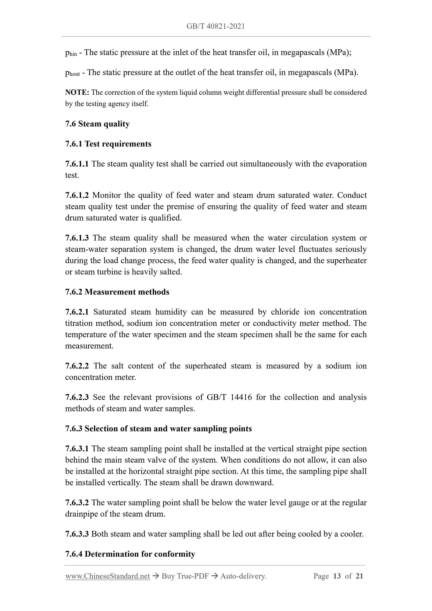
phin - The static pressure at the inlet of the heat transfer oil, in megapascals (MPa); phout - The static pressure at the outlet of the heat transfer oil, in megapascals (MPa). NOTE: The correction of the system liquid column weight differential pressure shall be considered by the testing agency itself.
7.6 Steam quality
7.6.1 Test requirements
7.6.1.1 The steam quality test shall be carried out simultaneously with the evaporation test.
7.6.1.2 Monitor the quality of feed water and steam drum saturated water. Conduct steam quality test under the premise of ensuring the quality of feed water and steam drum saturated water is qualified.
7.6.1.3 The steam quality shall be measured when the water circulation system or steam-water separation system is changed, the drum water level fluctuates seriously during the load change process, the feed water quality is changed, and the superheater or steam turbine is heavily salted.
7.6.2 Measurement methods
7.6.2.1 Saturated steam humidity can be measured by chloride ion concentration titration method, sodium ion concentration meter or conductivity meter method. The temperature of the water specimen and the steam specimen shall be the same for each measurement.
7.6.2.2 The salt content of the superheated steam is measured by a sodium ion concentration meter.
7.6.2.3 See the relevant provisions of GB/T 14416 for the collection and analysis methods of steam and water samples.
7.6.3 Selection of steam and water sampling points
7.6.3.1 The steam sampling point shall be installed at the vertical straight pipe section behind the main steam valve of the system. When conditions do not allow, it can also be installed at the horizontal straight pipe section. At this time, the sampling pipe shall be installed vertically. The steam shall be drawn downward.
7.6.3.2 The water sampling point shall be below the water level gauge or at the regular drainpipe of the steam drum.
7.6.3.3 Both steam and water sampling shall be led out after being cooled by a cooler. 7.6.4 Determination for conformity
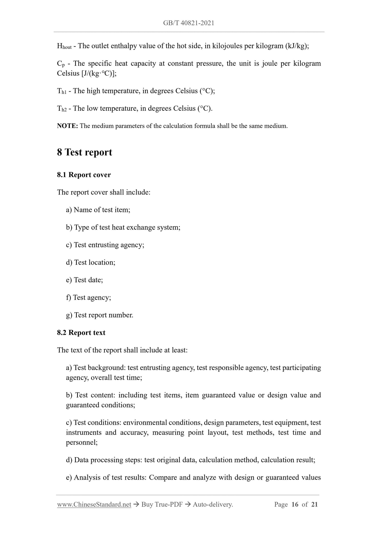
Hhout - The outlet enthalpy value of the hot side, in kilojoules per kilogram (kJ/kg); Cp - The specific heat capacity at constant pressure, the unit is joule per kilogram Celsius [J/(kg·℃)];
Th1 - The high temperature, in degrees Celsius (°C);
Th2 - The low temperature, in degrees Celsius (°C).
NOTE: The medium parameters of the calculation formula shall be the same medium. 8 Test report
8.1 Report cover
The report cover shall include:
a) Name of test item;
b) Type of test heat exchange system;
c) Test entrusting agency;
d) Test location;
e) Test date;
f) Test agency;
g) Test report number.
8.2 Report text
The text of the report shall include at least:
a) Test background: test entrusting agency, test responsible agency, test participating agency, overall test time;
b) Test content: including test items, item guaranteed value or design value and guaranteed conditions;
c) Test conditions: environmental conditions, design parameters, test equipment, test instruments and accuracy, measuring point layout, test methods, test time and personnel;
d) Data processing steps: test original data, calculation method, calculation result; e) Analysis of test results: Compare and analyze with design or guaranteed values

View full details