GB/T 40615-2021 English PDF (GBT40615-2021)
Regular price
$170.00 USD
Regular price
Sale price
$170.00 USD
Unit price
/
per
Delivery: 3 seconds. Download true-PDF + Invoice.
Get QUOTATION in 1-minute: Click GB/T 40615-2021
Historical versions: GB/T 40615-2021
Preview True-PDF (Reload/Scroll if blank)
GB/T 40615-2021: Guides of power system voltage stability evaluation
GB/T 40615-2021
NATIONAL STANDARD OF THE
PEOPLE’S REPUBLIC OF CHINA
ICS 29.020
CCS F 21
Guides of power system voltage stability evaluation
ISSUED ON. OCTOBER 11, 2021
IMPLEMENTED ON. MAY 01, 2022
Issued by. State Administration for Market Regulation;
Standardization Administration of the People's Republic of China.
Table of Contents
Foreword... 3
1 Scope... 4
2 Normative references... 4
3 Terms and definitions... 4
4 General principles... 5
5 Criteria for voltage stability evaluation... 6
6 Evaluation method for steady-state voltage stability... 7
7 Evaluation method for transient voltage stability... 11
8 Evaluation method for long-term voltage stability... 12
Guides of power system voltage stability evaluation
1 Scope
This document establishes the principles for evaluating the voltage stability of power
systems. It specifies the evaluation contents and methods for steady-state voltage
stability, transient voltage stability and long-term voltage stability.
This document is applicable to the calculation and analysis of voltage stability of power
systems of 110kV and above. For other voltage levels, it can refer to this document for
implementation.
2 Normative references
The following referenced documents are indispensable for the application of this
document. For dated references, only the edition cited applies. For undated references,
the latest edition of the referenced document (including any amendments) applies.
GB 38755-2019, Code on security and stability for power system
3 Terms and definitions
For the purposes of this document, the terms and definitions defined in GB 38755-2019
as well as the followings apply.
3.1 voltage stability
The ability that after the power system is subjected to small or large disturbances, the
system voltage can be maintained or recovered to the allowable range without voltage
collapse.
[Source. GB 38755-2019, 2.2.2]
3.2 voltage collapse
The process that when the system is in a state of voltage instability, the load continues
to try to obtain more power (active or reactive) by increasing the current, resulting in a
large-scale voltage drop in the system.
3.3 steady-state voltage stability
The ability that after the power system is subjected to a small disturbance, all the
busbars of the system maintain a stable voltage.
[Source. GB 38755-2019, 2.2.2.1]
3.4 transient voltage stability
The ability that after the power system is subjected to a large disturbance, all the busbars
of the system maintain a stable voltage.
[Source. GB 38755-2019, 2.2.2.2]
3.5 long-term voltage stability
The ability that after the power system is greatly disturbed, all the busbars of the system
maintain a stable voltage in the long-term process.
3.6 renewable energy station
All equipment below the grid connection point of the wind farm or photovoltaic power
station centrally connected to the power system.
NOTE. It includes transformers, busbars, lines, converters, energy storage, wind turbines,
photovoltaic power generation systems, reactive power adjustment equipment and auxiliary
equipment.
[Source. GB 38755-2019, 2.11]
3.7 multi-infeed DC short-circuit ratio; MSCR
The ratio of the short-circuit capacity of the DC-fed converter bus to the equivalent DC
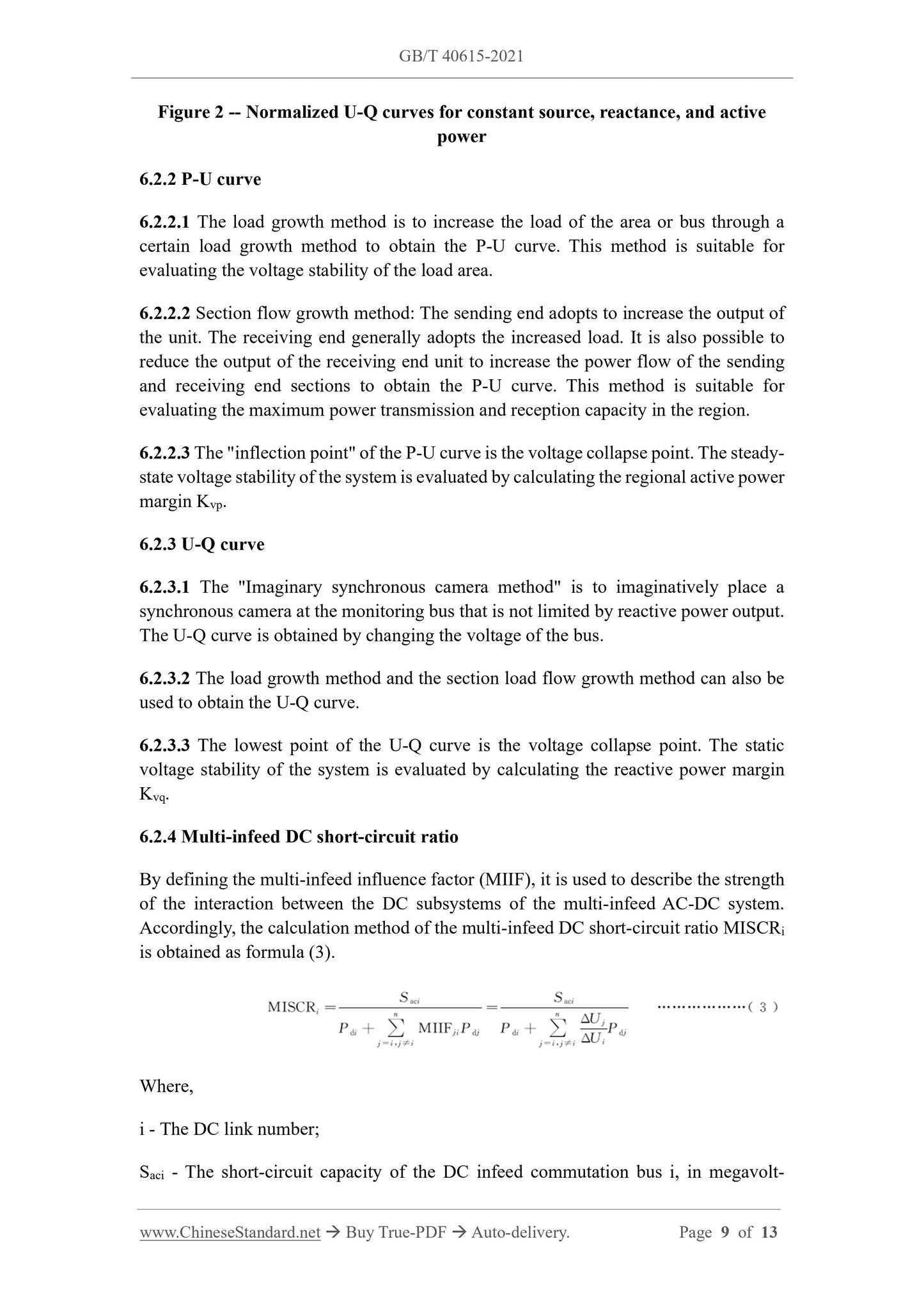
power after considering the influence of other DC circuits.
[Source. GB 38755-2019, 2.6]
4 General principles
4.1 Voltage stability evaluation is an important part of power system safety and stability
evaluation. The safety and stability evaluation of the power system shall include the
voltage stability evaluation.
4.2 The voltage stability evaluation of power system generally includes steady-state
voltage stability evaluation and transient voltage stability evaluation. In the post-fault
operation mode, the long-term voltage stability evaluation shall be used when the
steady-state voltage stability margin is low or the long-term component dynamic
characteristics such as over-excitation of the unit need to be considered.
5.2 Criteria for transient voltage stability evaluation
In the transient process after the power system is subjected to large disturbances, the
load bus voltage shall recover to above 0.80p.u. within 10s (this document selects the
average rated voltage as the voltage reference value). In new energy-intensive areas, it
shall be ensured that new energy stations are not disconnected from the grid and do not
repeatedly enter low voltage ride through. Care shall be taken to distinguish the voltage
drop near the oscillation center due to generator power angle oscillation and the voltage
drop due to transient voltage instability.
5.3 Criteria for long-term voltage stability evaluation
In the long-term process after the power system is subjected to large disturbances, the
load bus voltage shall be maintained or restored to above 0.90p.u. When judging by
simulation calculation, the response of long-term dynamic components and links shall
be included to reach a new balance point.
5.4 Selection of monitoring bus
In practical application of criteria for transient and long-term voltage stability
evaluation, the voltage monitoring point shall be selected at the load bus.
6 Evaluation method for steady-state voltage stability
6.1 Basic requirements
6.1.1 Before calculating and evaluating steady-state voltage stability, the simulation
model and calculation conditions shall be clarified, including partition division,
generator and new energy model, maximum reactive power that generator can generate,
generator output distribution method, terminal voltage, bus voltage, DC model, DC
power adjustment method, reactive power compensation model, transformer model,
load model, load growth method.
6.1.2 Simulation calculation shall use steady-state model. Among them, the generator
generally adopts the PV node model with upper and lower limit of reactive power. The
load shall use a constant power model. Based on the actual situation, the ZIP model can
also be used. The scale configuration can be carried out. Z, I, and P represent constant
impedance, constant current, and constant power, respectively.
6.1.3 The load growth mode has a great influence on the steady-state voltage stability.
It shall be determined according to the actual situation, or a typical growth method shall
be adopted. If the P-U curve is calculated, the load growth mode is constant power
factor growth. Calculate the U-Q curve. The load growth mode is the same as the active
power and the reactive power growth. The power output shall be determined according
to the load growth and the actual output distribution of the power grid.
Figure 2 -- Normalized U-Q curves for constant source, reactance, and active
power
6.2.2 P-U curve
6.2.2.1 The load growth method is to increase the load of the area or bus through a
certain load growth method to obtain the P-U curve. This method is suitable for
evaluating the voltage stability of the load area.
6.2.2.2 Section flow growth method. The sending end adopts to increase the output of
the unit. The receiving end generally adopts the increased load. It is also possible to
reduce the output of the receiving end unit to increase the power flow of the sending
and receiving end sections to obtain the P-U curve. This method is suitable for
evaluating the maximum power transmission and reception capacity in the region.
6.2.2.3 The "inflection point" of the P-U curve is the voltage collapse point. ...