Skip to product information
1 of 7

PayPal, credit cards. Download editable-PDF and invoice in 1 second!

GB/T 40430-2021 English PDF (GBT40430-2021)

GB/T 40430-2021 English PDF (GBT40430-2021)

Regular price $380.00 USD
Regular price Sale price $380.00 USD
Sale Sold out
Shipping calculated at checkout.
Delivery: 3 seconds. Download true-PDF + Invoice.
Get QUOTATION in 1-minute: Click GB/T 40430-2021
Historical versions: GB/T 40430-2021
Preview True-PDF (Reload/Scroll if blank)

GB/T 40430-2021: Road vehicles -- Diagnostic communication over controller area network (DoCAN) -- Dictionary
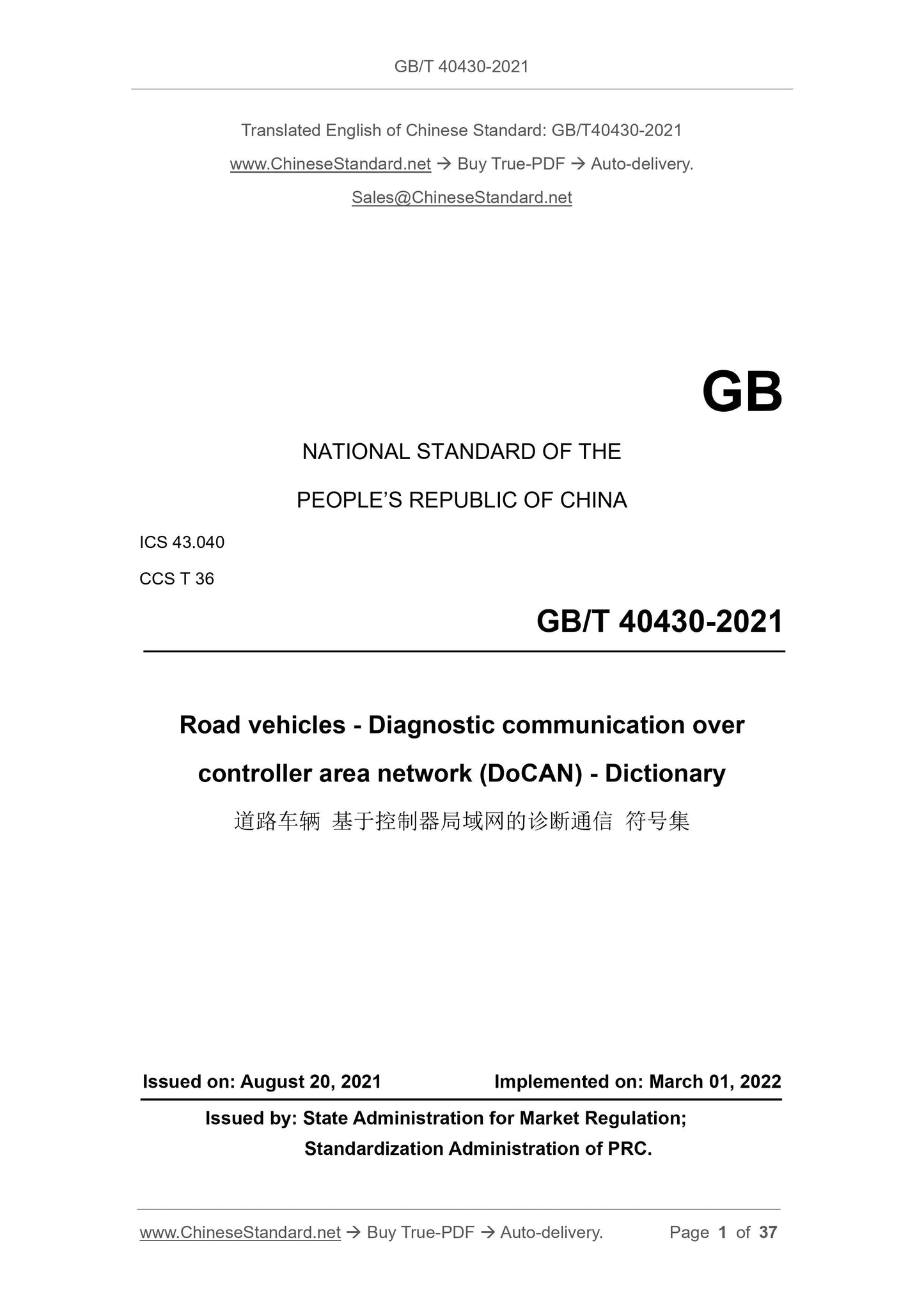
GB/T 40430-2021
GB
NATIONAL STANDARD OF THE
PEOPLE’S REPUBLIC OF CHINA
ICS 43.040
CCS T 36
Road vehicles - Diagnostic communication over
controller area network (DoCAN) - Dictionary
ISSUED ON: AUGUST 20, 2021
IMPLEMENTED ON: MARCH 01, 2022
Issued by: State Administration for Market Regulation;
Standardization Administration of PRC.
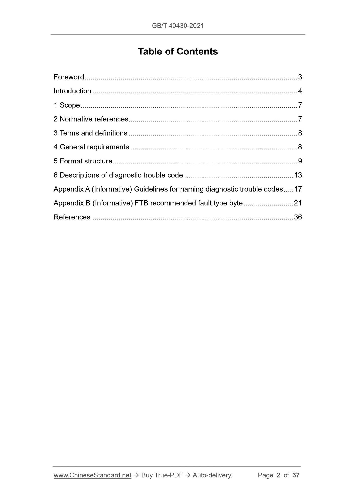
Table of Contents
Foreword ... 3 
Introduction ... 4 
1 Scope ... 7 
2 Normative references ... 7 
3 Terms and definitions ... 8 
4 General requirements ... 8 
5 Format structure ... 9 
6 Descriptions of diagnostic trouble code ... 13 
Appendix A (Informative) Guidelines for naming diagnostic trouble codes ... 17 
Appendix B (Informative) FTB recommended fault type byte ... 21 
References ... 36 
Road vehicles - Diagnostic communication over
controller area network (DoCAN) - Dictionary
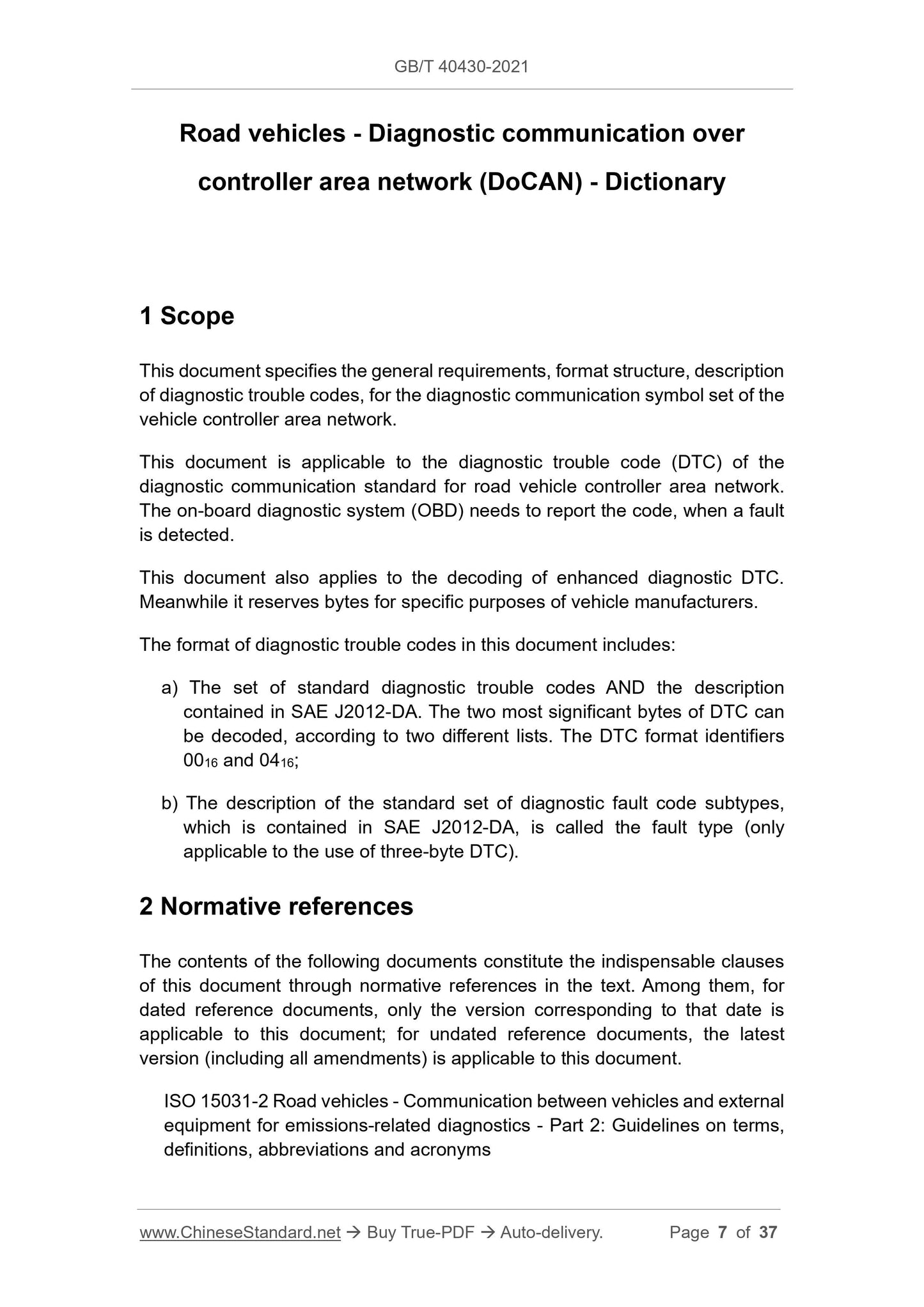
1 Scope
This document specifies the general requirements, format structure, description
of diagnostic trouble codes, for the diagnostic communication symbol set of the
vehicle controller area network.
This document is applicable to the diagnostic trouble code (DTC) of the
diagnostic communication standard for road vehicle controller area network.
The on-board diagnostic system (OBD) needs to report the code, when a fault
is detected.
This document also applies to the decoding of enhanced diagnostic DTC.
Meanwhile it reserves bytes for specific purposes of vehicle manufacturers.
The format of diagnostic trouble codes in this document includes:
a) The set of standard diagnostic trouble codes AND the description
contained in SAE J2012-DA. The two most significant bytes of DTC can
be decoded, according to two different lists. The DTC format identifiers
0016 and 0416;
b) The description of the standard set of diagnostic fault code subtypes,
which is contained in SAE J2012-DA, is called the fault type (only
applicable to the use of three-byte DTC).
2 Normative references
The contents of the following documents constitute the indispensable clauses
of this document through normative references in the text. Among them, for
dated reference documents, only the version corresponding to that date is
applicable to this document; for undated reference documents, the latest
version (including all amendments) is applicable to this document.
ISO 15031-2 Road vehicles - Communication between vehicles and external
equipment for emissions-related diagnostics - Part 2: Guidelines on terms,
definitions, abbreviations and acronyms
sub-fault strategies, are specified by four basic categories:
- Ordinary open-circuit;
- Scope/performance fault;
- Low circuit state;
- High circuit state.
The low circuit state is measured by external circuits, components or connected
systems. The signal type (voltage, frequency, etc.) shall be included behind the
low circuit state signal.
The high circuit state is measured by external circuits, components or
connected systems. The signal type (voltage, frequency, etc.) shall be included
behind the high circuit state signal.
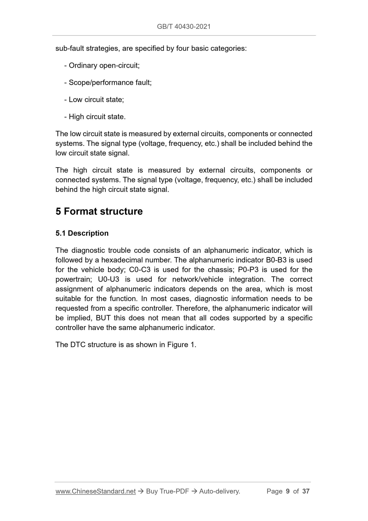
5 Format structure
5.1 Description
The diagnostic trouble code consists of an alphanumeric indicator, which is
followed by a hexadecimal number. The alphanumeric indicator B0-B3 is used
for the vehicle body; C0-C3 is used for the chassis; P0-P3 is used for the
powertrain; U0-U3 is used for network/vehicle integration. The correct
assignment of alphanumeric indicators depends on the area, which is most
suitable for the function. In most cases, diagnostic information needs to be
requested from a specific controller. Therefore, the alphanumeric indicator will
be implied, BUT this does not mean that all codes supported by a specific
controller have the same alphanumeric indicator.
The DTC structure is as shown in Figure 1.
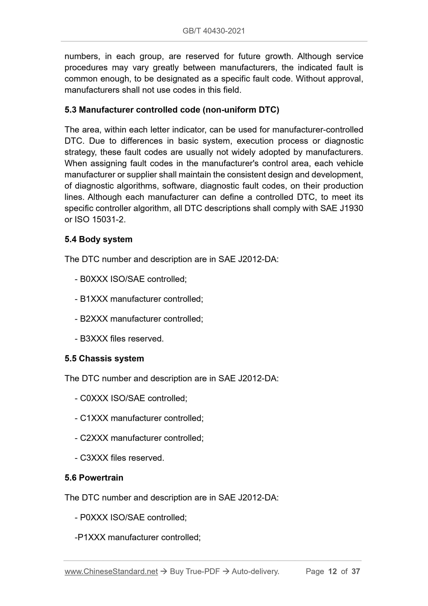
numbers, in each group, are reserved for future growth. Although service
procedures may vary greatly between manufacturers, the indicated fault is
common enough, to be designated as a specific fault code. Without approval,
manufacturers shall not use codes in this field.
5.3 Manufacturer controlled code (non-uniform DTC)
The area, within each letter indicator, can be used for manufacturer-controlled
DTC. Due to differences in basic system, execution process or diagnostic
strategy, these fault codes are usually not widely adopted by manufacturers.
When assigning fault codes in the manufacturer's control area, each vehicle
manufacturer or supplier shall maintain the consistent design and development,
of diagnostic algorithms, software, diagnostic fault codes, on their production
lines. Although each manufacturer can define a controlled DTC, to meet its
specific controller algorithm, all DTC descriptions shall comply with SAE J1930
or ISO 15031-2.
5.4 Body system
The DTC number and description are in SAE J2012-DA:
- B0XXX ISO/SAE controlled;
- B1XXX manufacturer controlled;
- B2XXX manufacturer controlled;
- B3XXX files reserved.
5.5 Chassis system
The DTC number and description are in SAE J2012-DA:
- C0XXX ISO/SAE controlled;
- C1XXX manufacturer controlled;
- C2XXX manufacturer controlled;
- C3XXX files reserved.
5.6 Powertrain
The DTC number and description are in SAE J2012-DA:
- P0XXX ISO/SAE controlled;
-P1XXX manufacturer controlled;
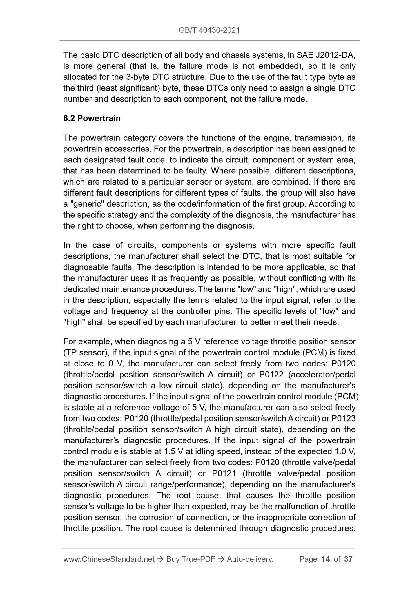
The basic DTC description of all body and chassis systems, in SAE J2012-DA,
is more general (that is, the failure mode is not embedded), so it is only
allocated for the 3-byte DTC structure. Due to the use of the fault type byte as
the third (least significant) byte, these DTCs only need to assign a single DTC
number and description to each component, not the failure mode.
6.2 Powertrain
The powertrain category covers the functions of the engine, transmission, its
powertrain accessories. For the powertrain, a description has been assigned to
each designated fault code, to indicate the circuit, component or system area,
that has been determined to be faulty. Where possible, different descriptions,
which are related to a particular sensor or system, are combined. If there are
different fault descriptions for different types of faults, the group will also have
a "generic" description, as the code/information of the first group. According to
the specific strategy and the complexity of the diagnosis, the manufacturer has
the right to choose, when performing the diagnosis.
In the case of circuits, components or systems with more specific fault
descriptions, the manufacturer shall select the DTC, that is most suitable for
diagnosable faults. The description is intended to be more applicable, so that
the manufacturer uses it as frequently as possible, without conflicting with its
dedicated maintenance procedures. The terms "low" and "high", which are used
in the description, especially the terms related to the input signal, refer to the
voltage and frequency at the controller pins. The specific levels of "low" and
"high" shall be specified by each manufacturer, to better meet their needs.
For example, when diagnosing a 5 V reference voltage throttle position sensor
(TP sensor), if the input signal of the powertrain control module (PCM) is fixed
at close to 0 V, the manufacturer can select freely from two codes: P0120
(throttle/pedal position sensor/switch A circuit) or P0122 (accelerator/pedal
position sensor/switch a low circuit state), depending on the manufacturer's
diagnostic procedures. If the input signal of the...
View full details