1
/
of
5
www.ChineseStandard.us -- Field Test Asia Pte. Ltd.
GB/T 40275-2021 English PDF (GB/T40275-2021)
GB/T 40275-2021 English PDF (GB/T40275-2021)
Regular price
$245.00
Regular price
Sale price
$245.00
Unit price
/
per
Shipping calculated at checkout.
Couldn't load pickup availability
GB/T 40275-2021: Textiles - Quantitative analysis of bicomponent fiber - Melting microscopy method
Delivery: 9 seconds. Download (and Email) true-PDF + Invoice.Get Quotation: Click GB/T 40275-2021 (Self-service in 1-minute)
Newer / historical versions: GB/T 40275-2021
Preview True-PDF
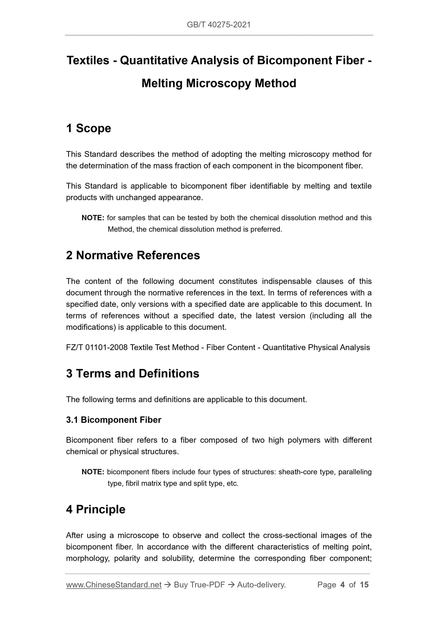
Scope
This Standard describes the method of adopting the melting microscopy method forthe determination of the mass fraction of each component in the bicomponent fiber.
This Standard is applicable to bicomponent fiber identifiable by melting and textile
products with unchanged appearance.
NOTE: for samples that can be tested by both the chemical dissolution method and this
Method, the chemical dissolution method is preferred.
Basic Data
| Standard ID | GB/T 40275-2021 (GB/T40275-2021) |
| Description (Translated English) | Textiles - Quantitative analysis of bicomponent fiber - Melting microscopy method |
| Sector / Industry | National Standard (Recommended) |
| Classification of Chinese Standard | W04 |
| Word Count Estimation | 14,138 |
| Issuing agency(ies) | State Administration for Market Regulation, China National Standardization Administration |
Share