1
/
of
10
www.ChineseStandard.us -- Field Test Asia Pte. Ltd.
GB/T 39851.3-2021 English PDF (GB/T39851.3-2021)
GB/T 39851.3-2021 English PDF (GB/T39851.3-2021)
Regular price
$485.00
Regular price
Sale price
$485.00
Unit price
/
per
Shipping calculated at checkout.
Couldn't load pickup availability
GB/T 39851.3-2021: Road vehicles - Diagnostic communication over Controller Area Network (DoCAN) - Part 3: Requirements for emissions-related systems
Delivery: 9 seconds. Download (and Email) true-PDF + Invoice.Get Quotation: Click GB/T 39851.3-2021 (Self-service in 1-minute)
Newer / historical versions: GB/T 39851.3-2021
Preview True-PDF
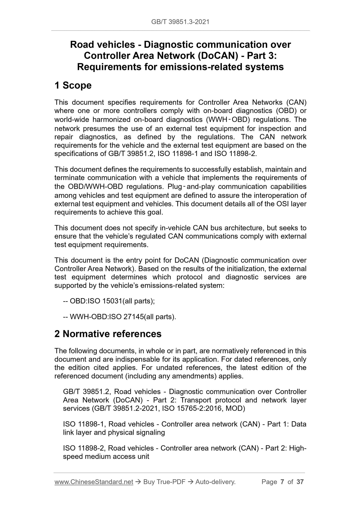
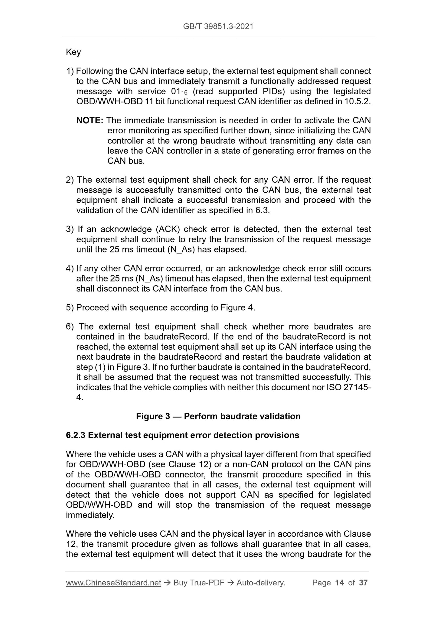
Scope
This document specifies requirements for Controller Area Networks (CAN)where one or more controllers comply with on-board diagnostics (OBD) or
world-wide harmonized on-board diagnostics (WWH‑OBD) regulations. The
network presumes the use of an external test equipment for inspection and
repair diagnostics, as defined by the regulations. The CAN network
requirements for the vehicle and the external test equipment are based on the
specifications of GB/T 39851.2, ISO 11898-1 and ISO 11898-2.
This document defines the requirements to successfully establish, maintain and
terminate communication with a vehicle that implements the requirements of
the OBD/WWH-OBD regulations. Plug‑and-play communication capabilities
among vehicles and test equipment are defined to assure the interoperation of
external test equipment and vehicles. This document details all of the OSI layer
requirements to achieve this goal.
This document does not specify in-vehicle CAN bus architecture, but seeks to
ensure that the vehicle’s regulated CAN communications comply with external
test equipment requirements.
This document is the entry point for DoCAN (Diagnostic communication over
Controller Area Network). Based on the results of the initialization, the external
test equipment determines which protocol and diagnostic services are
supported by the vehicle’s emissions-related system:
-- OBD:ISO 15031(all parts);
-- WWH-OBD:ISO 27145(all parts).
Basic Data
| Standard ID | GB/T 39851.3-2021 (GB/T39851.3-2021) |
| Description (Translated English) | Road vehicles - Diagnostic communication over Controller Area Network (DoCAN) - Part 3: Requirements for emissions-related systems |
| Sector / Industry | National Standard (Recommended) |
| Classification of Chinese Standard | T35 |
| Word Count Estimation | 29,257 |
| Issuing agency(ies) | State Administration for Market Regulation, China National Standardization Administration |
Share