


1
/
of
10
www.ChineseStandard.us -- Field Test Asia Pte. Ltd.
GB/T 39648-2020 English PDF (GB/T39648-2020)
GB/T 39648-2020 English PDF (GB/T39648-2020)
Regular price
$260.00
Regular price
Sale price
$260.00
Unit price
/
per
Shipping calculated at checkout.
Couldn't load pickup availability
GB/T 39648-2020: Textiles - Tests for colour fastness - Determination of colour fastness grades by digital imaging techniques
Delivery: 9 seconds. Download (and Email) true-PDF + Invoice.Get Quotation: Click GB/T 39648-2020 (Self-service in 1-minute)
Newer / historical versions: GB/T 39648-2020
Preview True-PDF
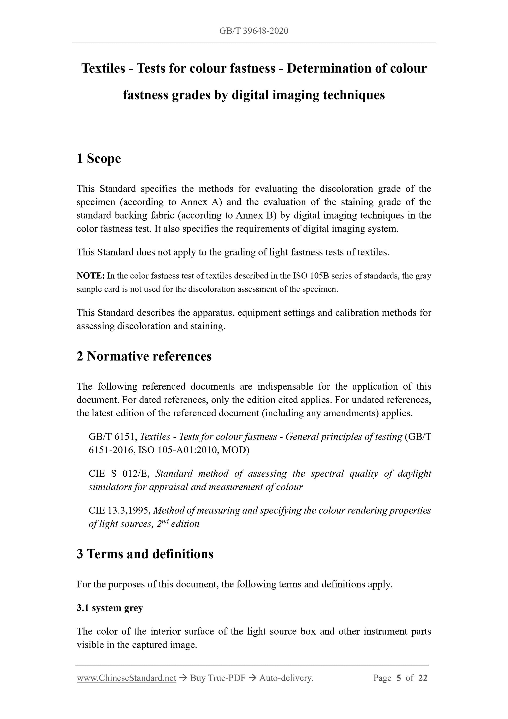
Scope
This Standard specifies the methods for evaluating the discoloration grade of thespecimen (according to Annex A) and the evaluation of the staining grade of the
standard backing fabric (according to Annex B) by digital imaging techniques in the
color fastness test. It also specifies the requirements of digital imaging system.
This Standard does not apply to the grading of light fastness tests of textiles.
NOTE: In the color fastness test of textiles described in the ISO 105B series of standards, the gray
sample card is not used for the discoloration assessment of the specimen.
This Standard describes the apparatus, equipment settings and calibration methods for
assessing discoloration and staining.
Basic Data
| Standard ID | GB/T 39648-2020 (GB/T39648-2020) |
| Description (Translated English) | Textiles - Tests for colour fastness - Determination of colour fastness grades by digital imaging techniques |
| Sector / Industry | National Standard (Recommended) |
| Classification of Chinese Standard | W04 |
| Classification of International Standard | 59.080.01 |
| Word Count Estimation | 16,198 |
| Date of Issue | 2020-12-14 |
| Date of Implementation | 2021-07-01 |
| Quoted Standard | GB/T 6151; CIE S 012/E; CIE 13.3-1995 |
| Adopted Standard | ISO 105-A11-2012, MOD |
| Regulation (derived from) | National Standard Announcement No. 28 of 2020 |
| Issuing agency(ies) | State Administration for Market Regulation, China National Standardization Administration |
| Summary | This standard specifies the method for evaluating the color fastness test of the sample by digital image technology (according to Appendix A) and standard lining fabric staining level evaluation (according to Appendix B), and specifies the requirements of the digital image system. This standard does not apply to the grading of textiles' light fastness test. This standard describes the equipment, equipment settings and calibration methods for evaluating discoloration and staining. |
Share