1
/
of
12
www.ChineseStandard.us -- Field Test Asia Pte. Ltd.
GB/T 39086-2020 English PDF (GB/T39086-2020)
Regular price
$425.00
Regular price
Sale price
$425.00
Unit price
/
per
Shipping calculated at checkout.
Couldn't load pickup availability
GB/T 39086-2020: Functional Safety Requirements and Testing Methods for Battery Management System of Electric Vehicles
Delivery: 9 seconds. Download (& Email) true-PDF + Invoice.
Get Quotation: Click GB/T 39086-2020 (Self-service in 1-minute)
Historical versions (Master-website): GB/T 39086-2020
Preview True-PDF (Reload/Scroll-down if blank)
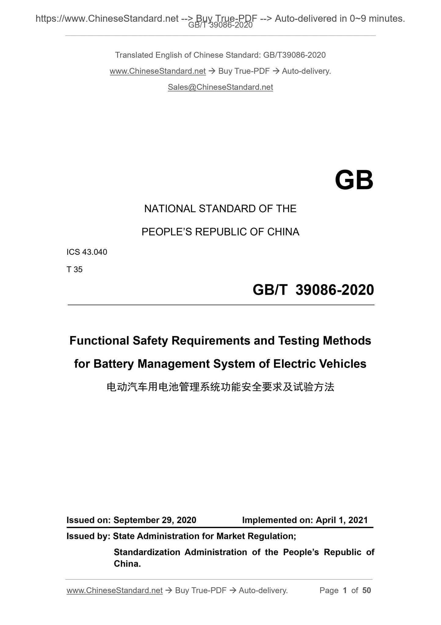
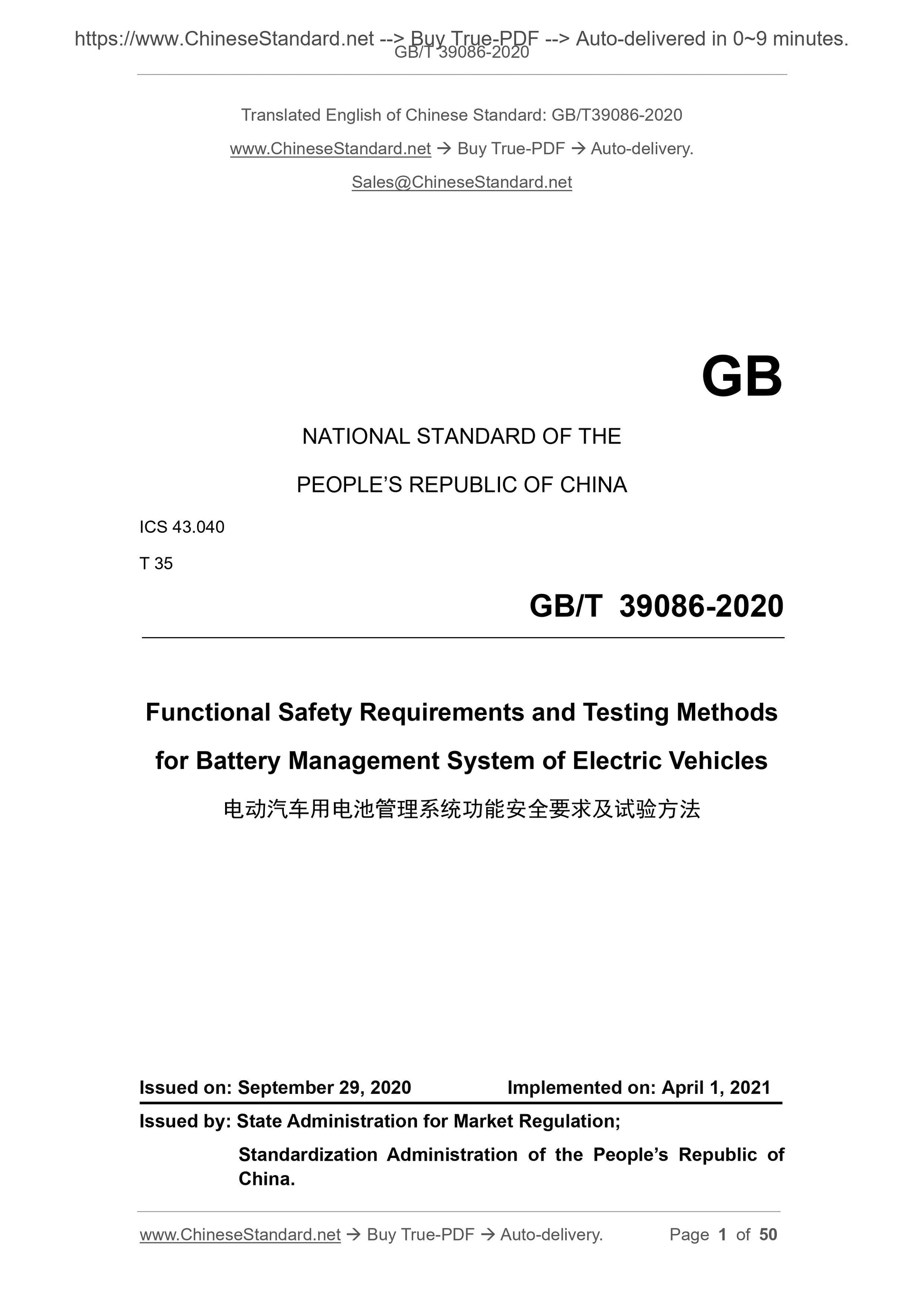
GB/T 39086-2020
GB
NATIONAL STANDARD OF THE
PEOPLE’S REPUBLIC OF CHINA
ICS 43.040
T 35
Functional Safety Requirements and Testing Methods
for Battery Management System of Electric Vehicles
ISSUED ON: SEPTEMBER 29, 2020
IMPLEMENTED ON: APRIL 1, 2021
Issued by: State Administration for Market Regulation;
Standardization Administration of the People’s Republic of
China.
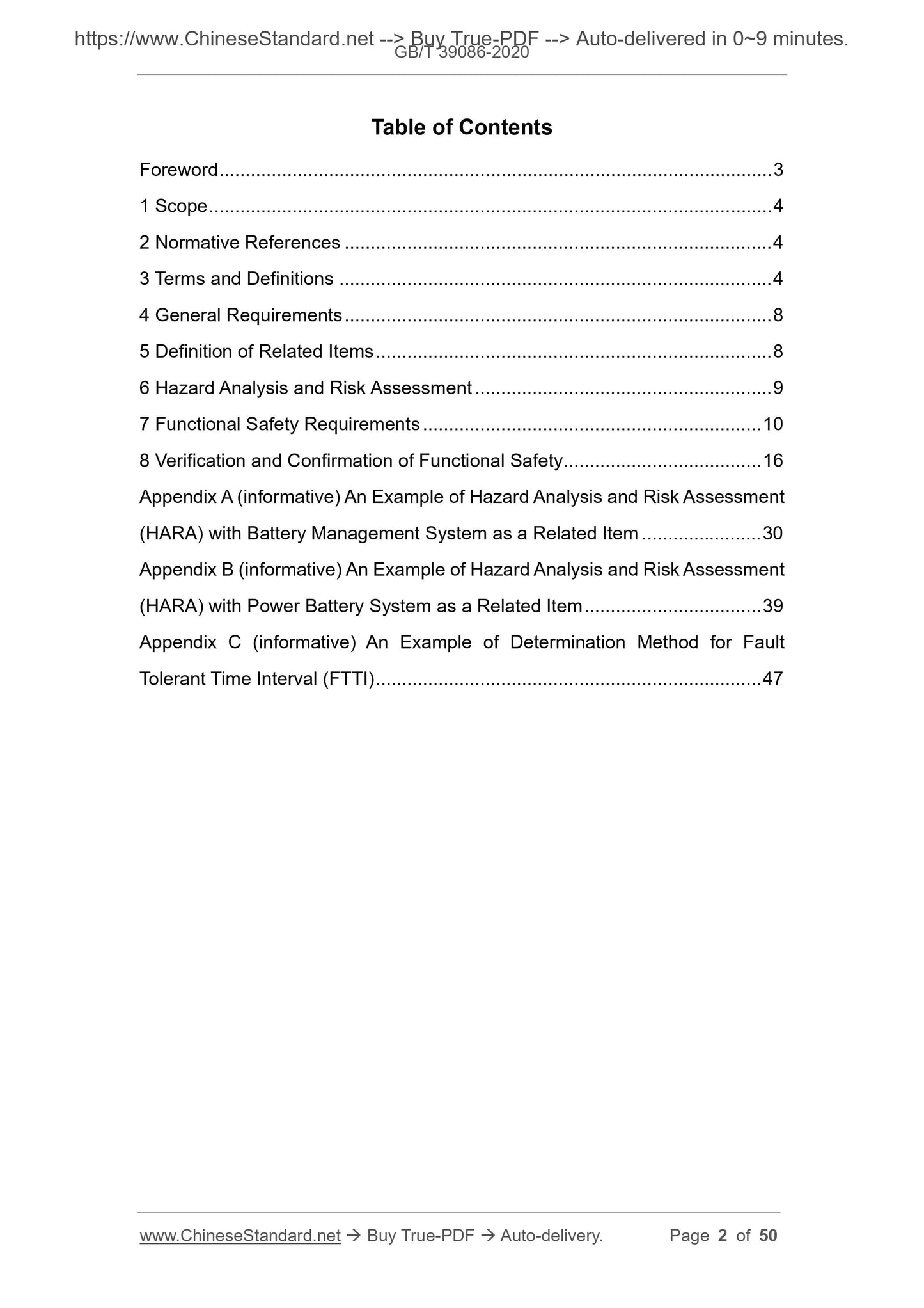
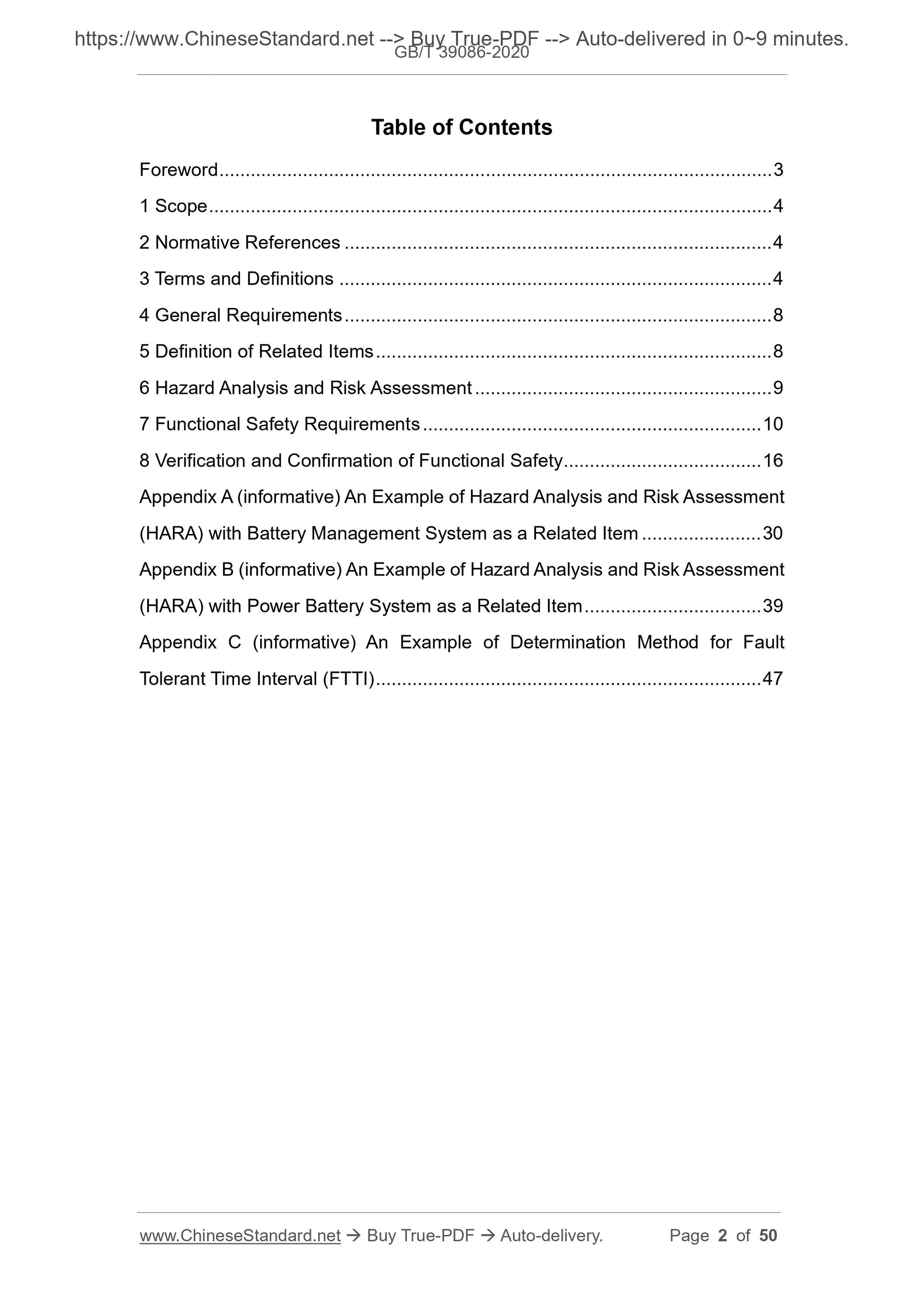
Table of Contents
Foreword ... 3
1 Scope ... 4
2 Normative References ... 4
3 Terms and Definitions ... 4
4 General Requirements ... 8
5 Definition of Related Items ... 8
6 Hazard Analysis and Risk Assessment ... 9
7 Functional Safety Requirements ... 10
8 Verification and Confirmation of Functional Safety ... 16
Appendix A (informative) An Example of Hazard Analysis and Risk Assessment
(HARA) with Battery Management System as a Related Item ... 30
Appendix B (informative) An Example of Hazard Analysis and Risk Assessment
(HARA) with Power Battery System as a Related Item ... 39
Appendix C (informative) An Example of Determination Method for Fault
Tolerant Time Interval (FTTI) ... 47
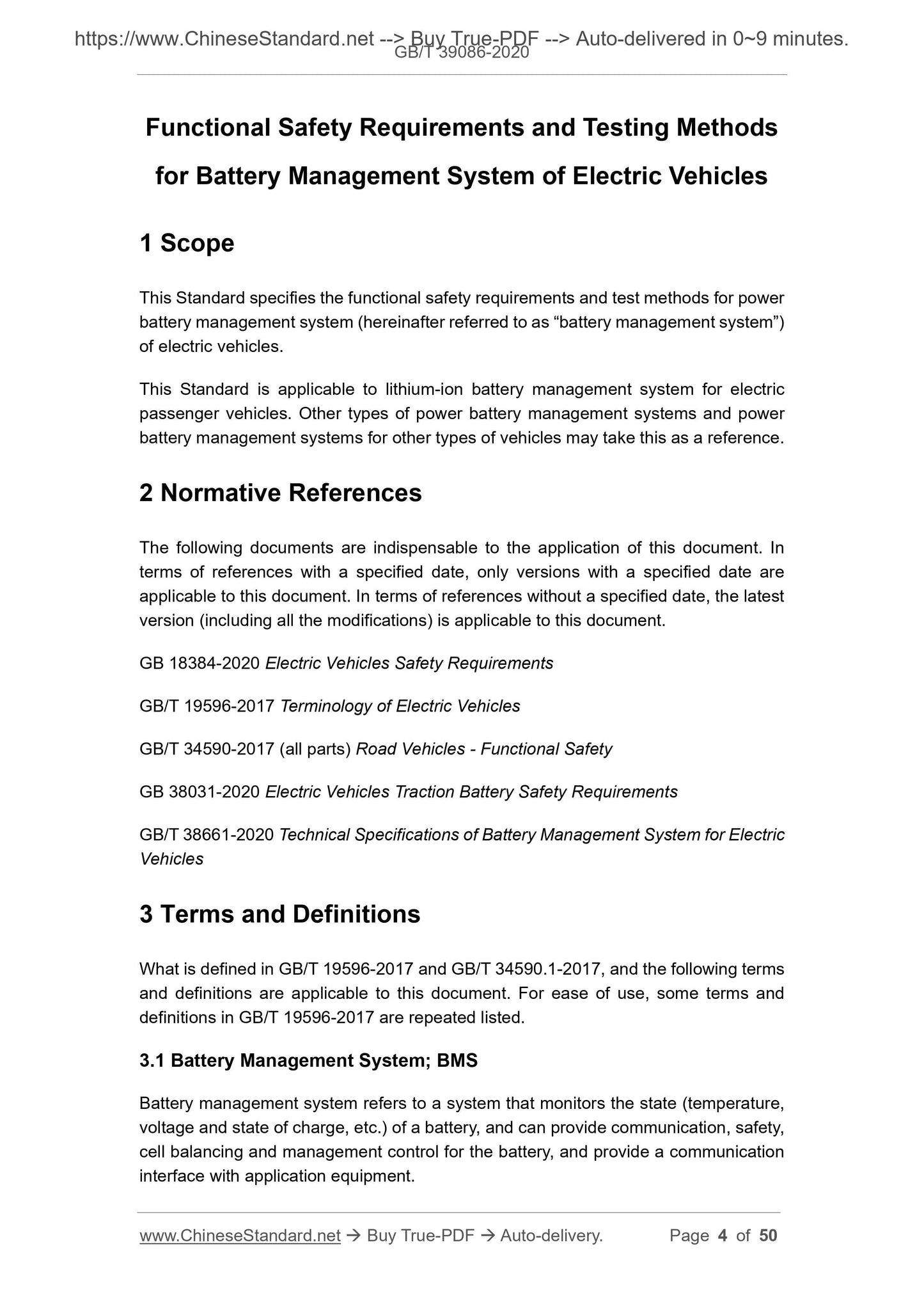
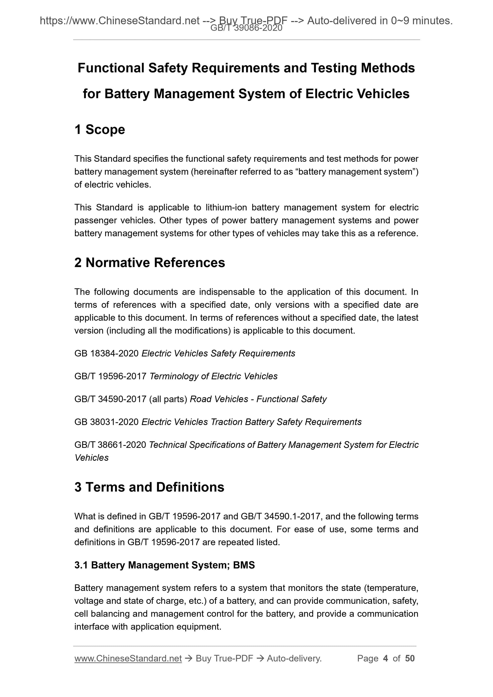
Functional Safety Requirements and Testing Methods
for Battery Management System of Electric Vehicles
1 Scope
This Standard specifies the functional safety requirements and test methods for power
battery management system (hereinafter referred to as “battery management system”)
of electric vehicles.
This Standard is applicable to lithium-ion battery management system for electric
passenger vehicles. Other types of power battery management systems and power
battery management systems for other types of vehicles may take this as a reference.
2 Normative References
The following documents are indispensable to the application of this document. In
terms of references with a specified date, only versions with a specified date are
applicable to this document. In terms of references without a specified date, the latest
version (including all the modifications) is applicable to this document.
GB 18384-2020 Electric Vehicles Safety Requirements
GB/T 19596-2017 Terminology of Electric Vehicles
GB/T 34590-2017 (all parts) Road Vehicles - Functional Safety
GB 38031-2020 Electric Vehicles Traction Battery Safety Requirements
GB/T 38661-2020 Technical Specifications of Battery Management System for Electric
Vehicles
3 Terms and Definitions
What is defined in GB/T 19596-2017 and GB/T 34590.1-2017, and the following terms
and definitions are applicable to this document. For ease of use, some terms and
definitions in GB/T 19596-2017 are repeated listed.
3.1 Battery Management System; BMS
Battery management system refers to a system that monitors the state (temperature,
voltage and state of charge, etc.) of a battery, and can provide communication, safety,
cell balancing and management control for the battery, and provide a communication
interface with application equipment.
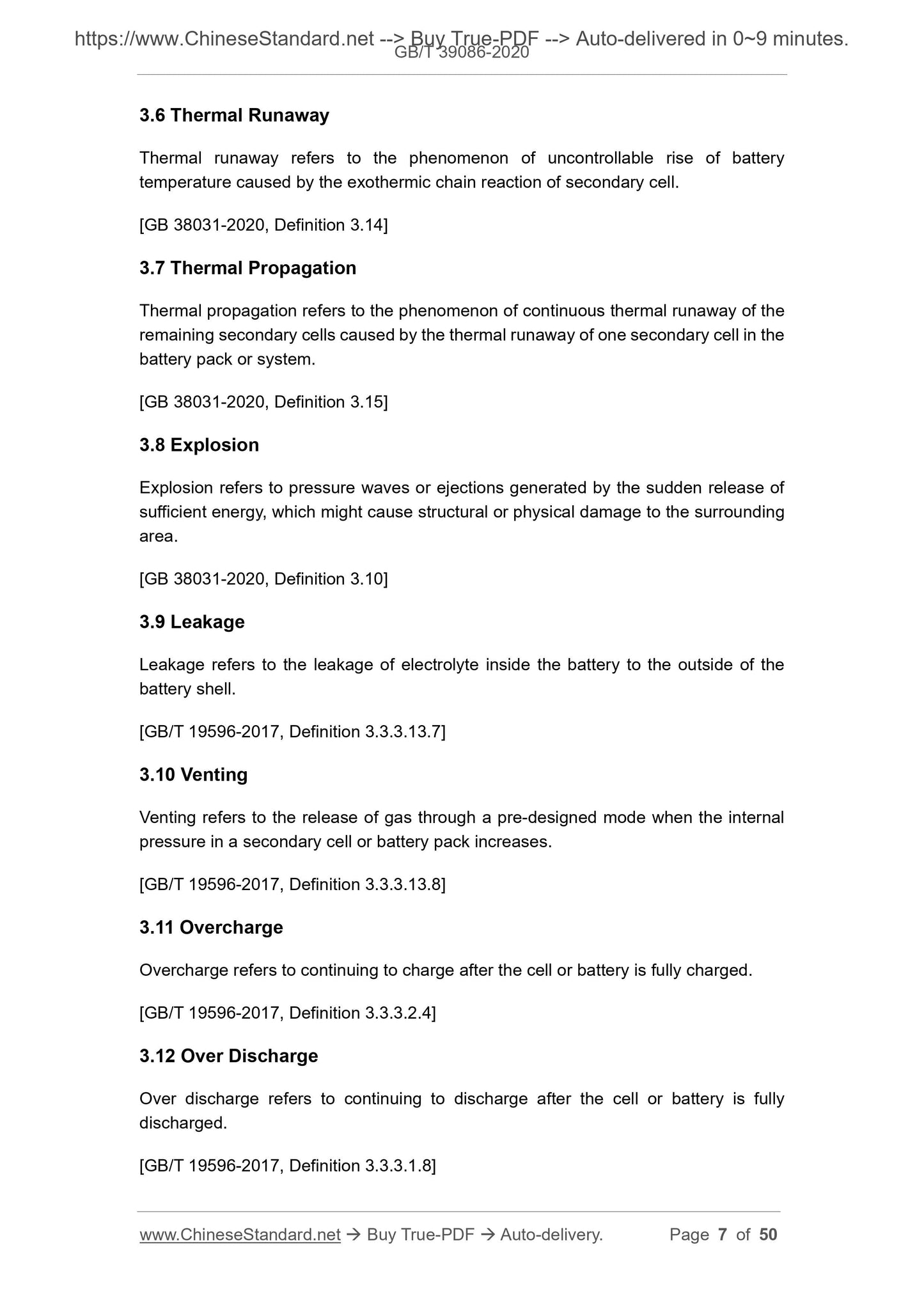
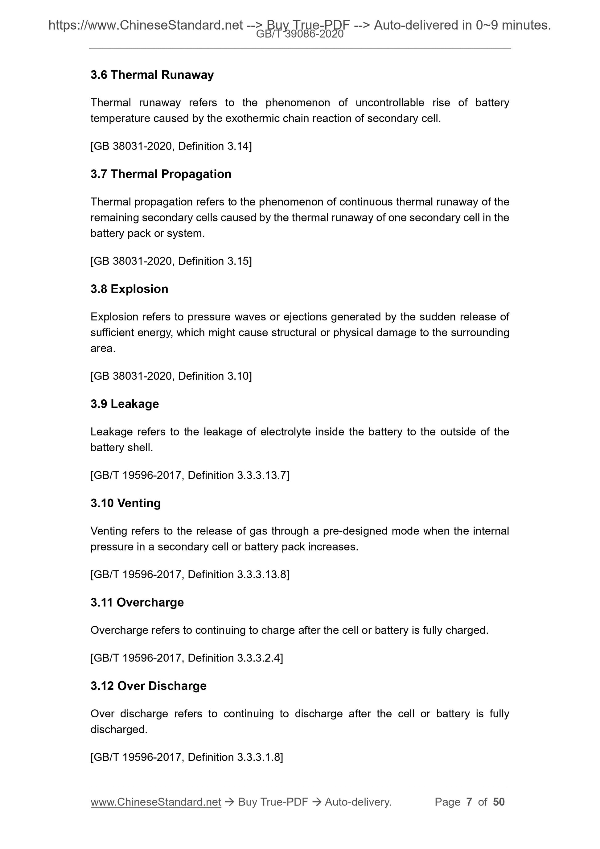
3.6 Thermal Runaway
Thermal runaway refers to the phenomenon of uncontrollable rise of battery
temperature caused by the exothermic chain reaction of secondary cell.
[GB 38031-2020, Definition 3.14]
3.7 Thermal Propagation
Thermal propagation refers to the phenomenon of continuous thermal runaway of the
remaining secondary cells caused by the thermal runaway of one secondary cell in the
battery pack or system.
[GB 38031-2020, Definition 3.15]
3.8 Explosion
Explosion refers to pressure waves or ejections generated by the sudden release of
sufficient energy, which might cause structural or physical damage to the surrounding
area.
[GB 38031-2020, Definition 3.10]
3.9 Leakage
Leakage refers to the leakage of electrolyte inside the battery to the outside of the
battery shell.
[GB/T 19596-2017, Definition 3.3.3.13.7]
3.10 Venting
Venting refers to the release of gas through a pre-designed mode when the internal
pressure in a secondary cell or battery pack increases.
[GB/T 19596-2017, Definition 3.3.3.13.8]
3.11 Overcharge
Overcharge refers to continuing to charge after the cell or battery is fully charged.
[GB/T 19596-2017, Definition 3.3.3.2.4]
3.12 Over Discharge
Over discharge refers to continuing to discharge after the cell or battery is fully
discharged.
[GB/T 19596-2017, Definition 3.3.3.1.8]
3.13 Fire
Fire refers to the continuous combustion of secondary cells, modules, battery packs or
any parts of the system (flame duration is greater than 1 s).
NOTE 1: “flame duration is greater than 1 s” refers to the duration of a single flame, rather
than the cumulative time of multiple flames.
NOTE 2: sparks and arcs do not belong to combustion.
[GB 38031-2020, Definition 3.11]
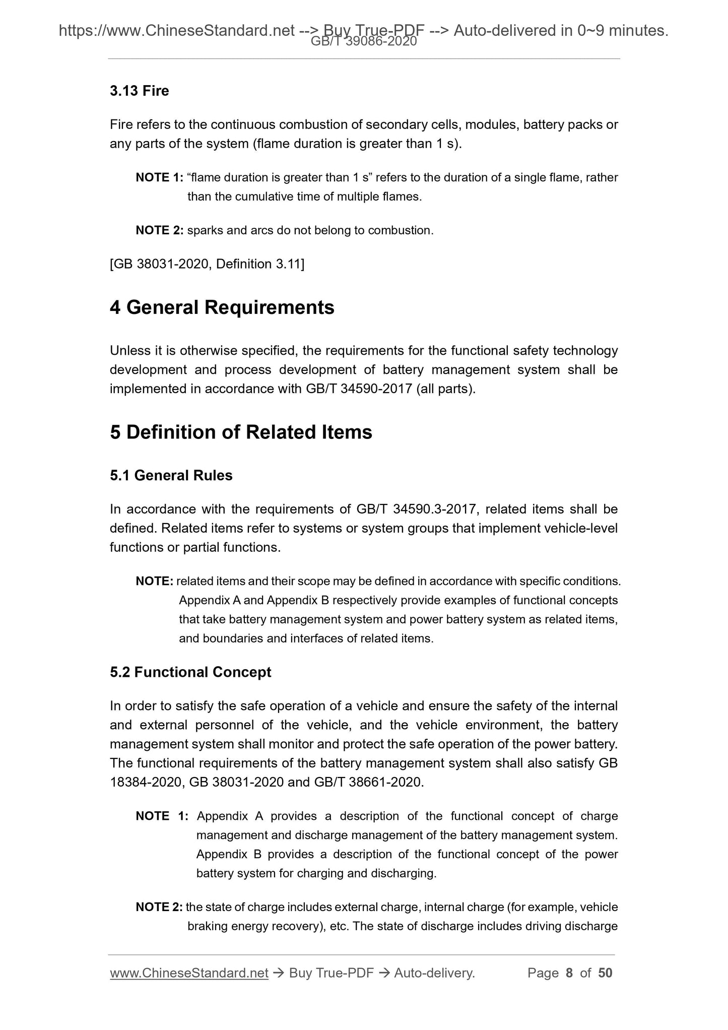
4 General Requirements
Unless it is otherwise specified, the requirements for the functional safety technology
development and process development of battery management system shall be
implemented in accordance with GB/T 34590-2017 (all parts).
5 Definition of Related Items
5.1 General Rules
In accordance with the requirements of GB/T 34590.3-2017, related items shall be
defined. Related items refer to systems or system groups that implement vehicle-level
functions or partial functions.
NOTE: related items and their scope may be defined in accordance with specific conditions.
Appendix A and Appendix B respectively provide examples of functional concepts
that take battery management system and power battery system as related items,
and boundaries and interfaces of related items.
5.2 Functional Concept
In order to satisfy the safe operation of a vehicle and ensure the safety of the internal
and external personnel of the vehicle, and the vehicle environment, the battery
management system shall monitor and protect the safe operation of the power battery.
The functional requirements of the battery management system shall also satisfy GB
18384-2020, GB 38031-2020 and GB/T 38661-2020.
NOTE 1: Appendix A provides a description of the functional concept of charge
management and discharge management of the battery management system.
Appendix B provides a description of the functional concept of the power
battery system for charging and discharging.
NOTE 2: the state of charge includes external charge, internal charge (for example, vehicle
braking energy recovery), etc. The state of discharge includes driving discharge
parties through negotiation.
7.2.5 Alarm and degradation concept
After the battery management system detects an over-discharging fault of secondary
cell, it shall warn the driver through warning signals or prompt messages.
If there are scenarios where the power battery cannot immediately enter or maintain
the safe state, a degradation function (for example, limitation of charging power and
prohibition of the use of braking energy recovery function) shall be designed to put the
vehicle into the emergency operation mode.
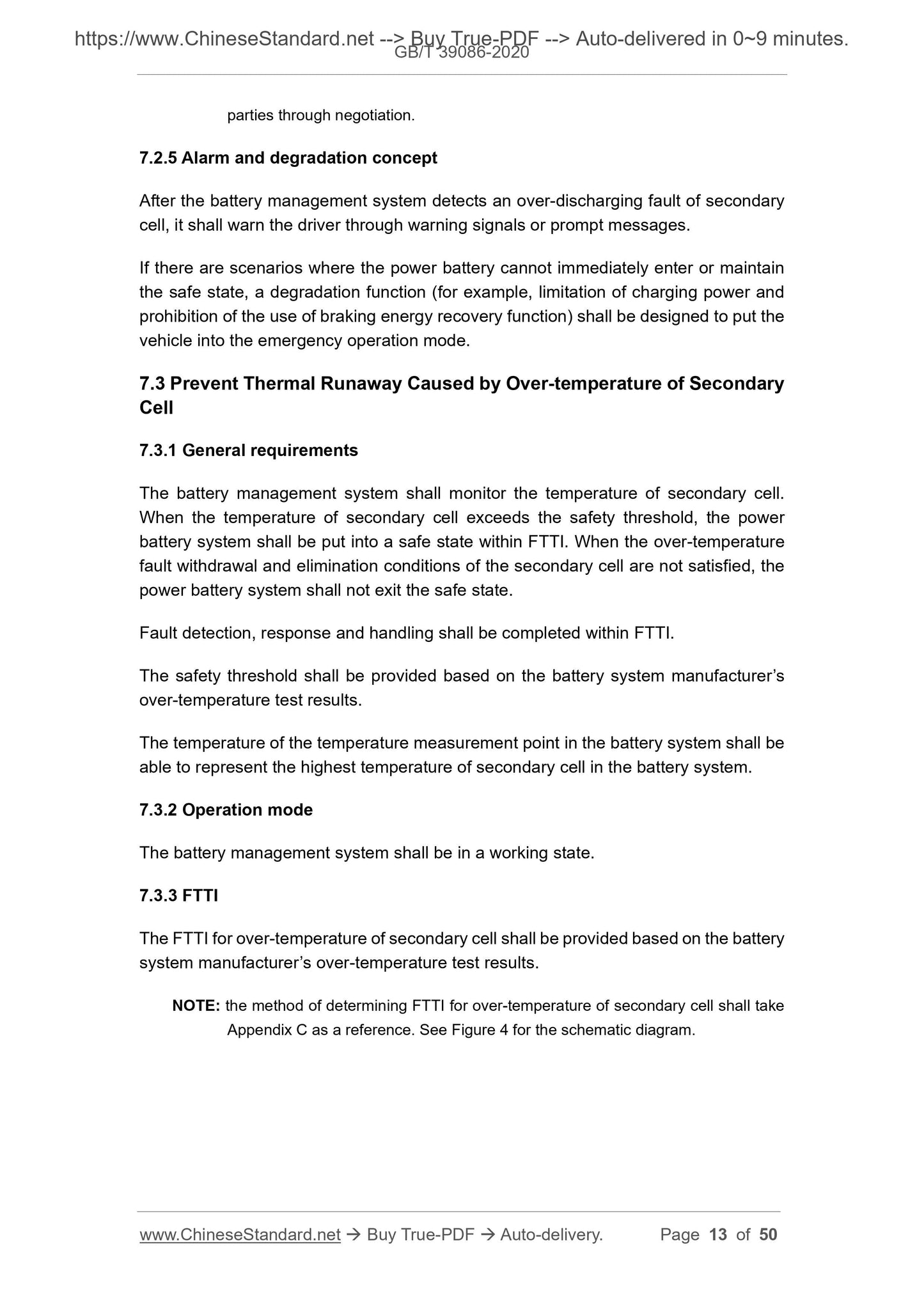
7.3 Prevent Thermal Runaway Caused by Over-temperature of Secondary
Cell
7.3.1 General requirements
The battery management system shall monitor the temperature of secondary cell.
When the temperature of secondary cell exceeds the safety threshold, the power
battery system shall be put into a safe state within FTTI. When the over-temperature
fault withdrawal and elimination conditions of the secondary cell are not satisfied, the
power battery system shall not exit the safe state.
Fault detection, response and handling shall be completed within FTTI.
The safety threshold shall be provided based on the battery system manufacturer’s
over-temperature test results.
The temperature of the temperature measurement point in the battery system shall be
able to represent the highest temperature of secondary cell in the battery system.
7.3.2 Operation mode
The battery management system shall be in a working state.
7.3.3 FTTI
The FTTI for over-temperature of secondary cell shall be provided based on the battery
system manufacturer’s over-temperature test results.
NOTE: the method of determining FTTI for over-temperature of secondary cell shall take
Appendix C as a reference. See Figure 4 for the schematic diagram.
parties through negotiation.
7.4.5 Alarm and degradation concept
After the battery management system detects an overcurrent fault of the power battery
system, it shall warn the driver through warning signals or prompt messages.
If there are scenarios where the power battery cannot immediately enter or maintain
the safe state, a degradation function (for example, limitation of charging and
discharging power, and prohibition of the operation of some non-safe-operation-related
functions) shall be designed to put the vehicle into the emergency operation mode.
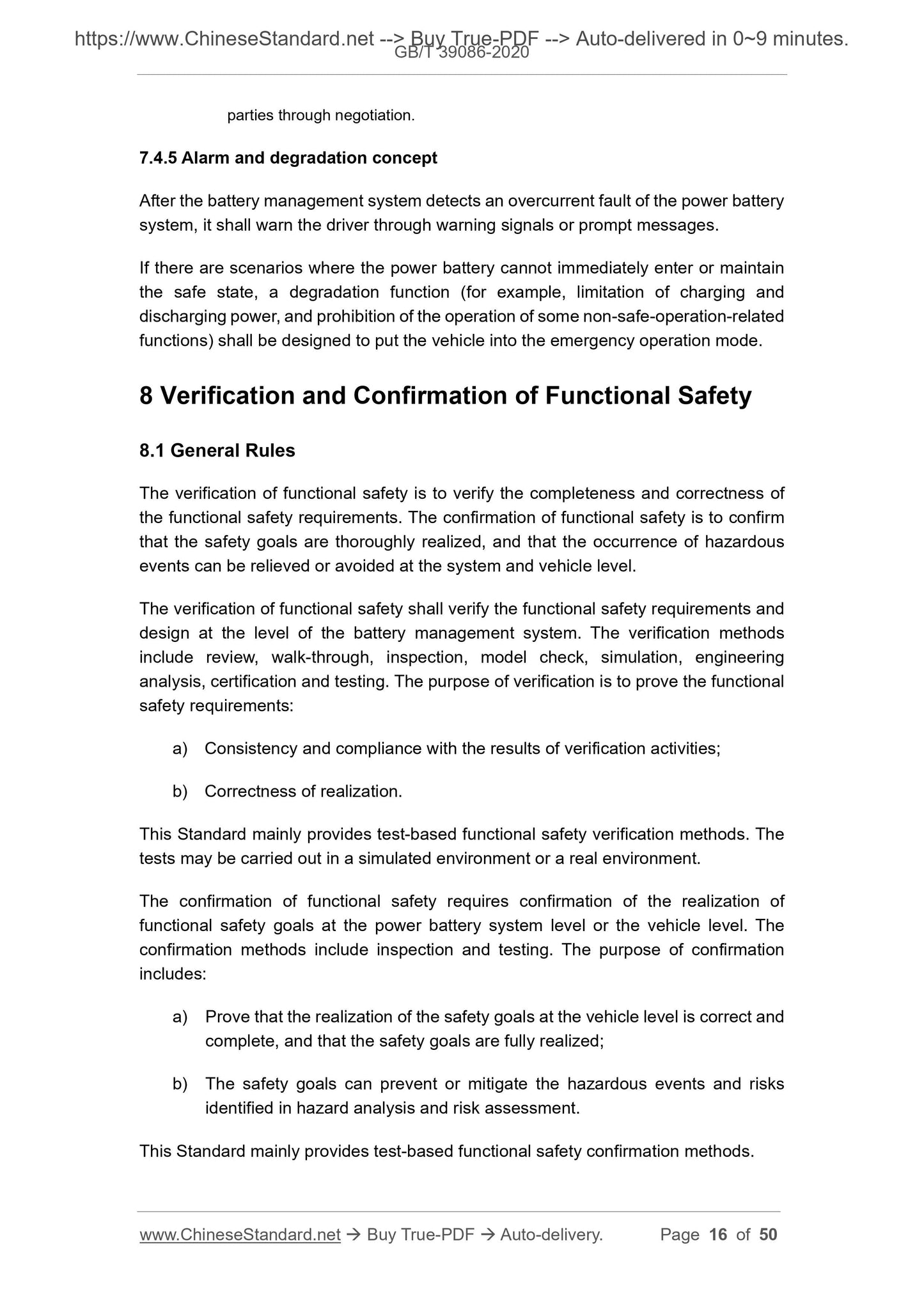
8 Verification and Confirmation of Functional Safety
8.1 General Rules
The verification of functional safety is to verify the completeness and correctness of
the functional safety requirements. The confirmation of functional safety is to confirm
that the safety goals are thoroughly realized, and that the occurrence of hazardous
events can be relieved or avoided at the system and vehicle level.
The verification of functional safety shall verify the functional safety requirements and
design at the level of the battery management system. The verification methods
include review, walk-through, inspection, model check, simulation, engineering
analysis, certification and testing. The purpose of verification is to prove the functional
safety requirements:
a) Consistency and compliance with the results of verification activities;
b) Correctness of realization.
This Standard mainly provides test-based functional safety verification methods. The
tests may be carried out in a simulated environment or a real environment.
The confirmation of functional safety requires confirmation of the realization of
functional safety goals at the power battery system level or the vehicle level. The
confirmation methods include inspection and testing. The purpose of confirmation
includes:
a) Prove that the realization of the safety goals at the vehicle level is correct and
complete, and that the safety goals are fully realized;
b) The safety goals can prevent or mitigate the hazardous events and risks
identified in hazard analysis and risk assessment.
This Standard mainly provides test-based functional safety confirmation methods.
d) The test shall monitor the process of the battery management system entering
a safe state (such as: safety threshold, time and state switching);
e) The test shall monitor the conditions, under which, the battery management
system exits the safe state.
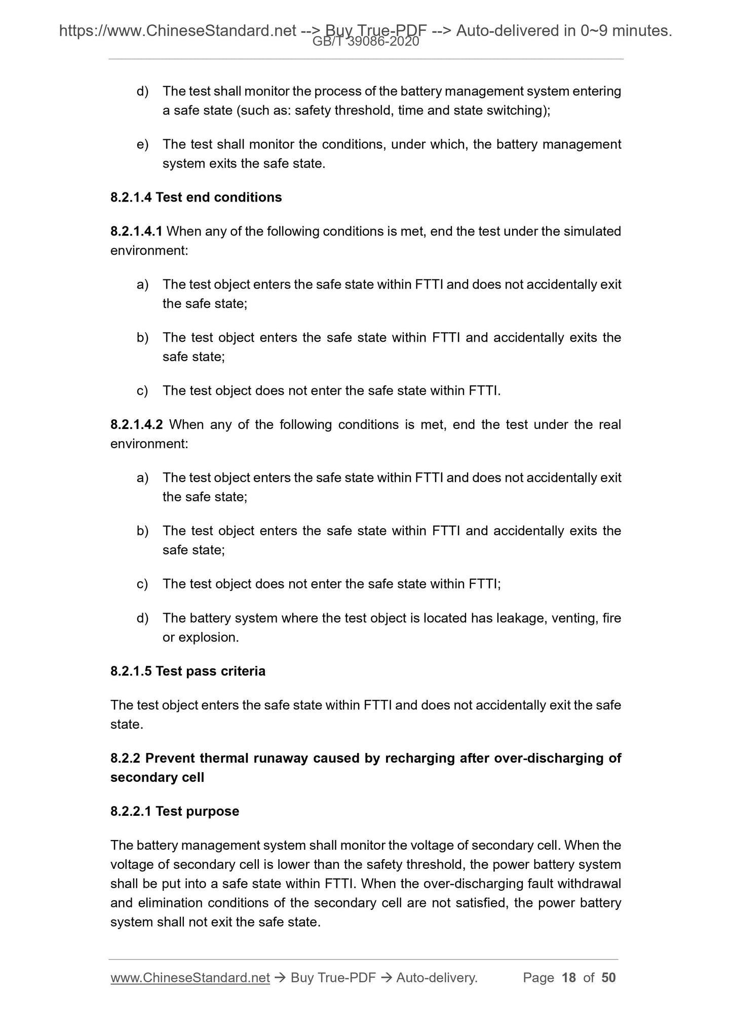
8.2.1.4 Test end conditions
8.2.1.4.1 When any of the following conditions is met, end the test under the simulated
environment:
a) The test object enters the safe state within FTTI and does not accidentally exit
the safe state;
b) The test object enters the safe state within FTTI and accidentally exits the
safe state;
c) The test object does not enter the safe state within FTTI.
8.2.1.4.2 When any of the following conditions is met, end the test under the real
environment:
a) The test object enters the safe state within FTTI and does not accidentally exit
the safe state;
b) The test object enters the safe state within FTTI and accidentally exits the
safe state;
c) The test object does not enter the safe state within FTTI;
d) The battery system where the test object is located has leakage, venting, fire
or explosion.
8.2.1.5 Test pass criteria
The test object enters the safe state within FTTI and does not accidentally exit the safe
state.
8.2.2 Prevent thermal runaway caused by recharging after over-discharging of
secondary cell
8.2.2.1 Test purpose
The battery management system shall monitor the voltage of secondary cell. When the
voltage of secondary cell is lower than the safety threshold, the power battery system
shall be put into a safe state within FTTI. When the over-discharging fault withdrawal
and elimination conditions of the secondary cell are not satisfied, the power battery
system shall not exit the safe state.
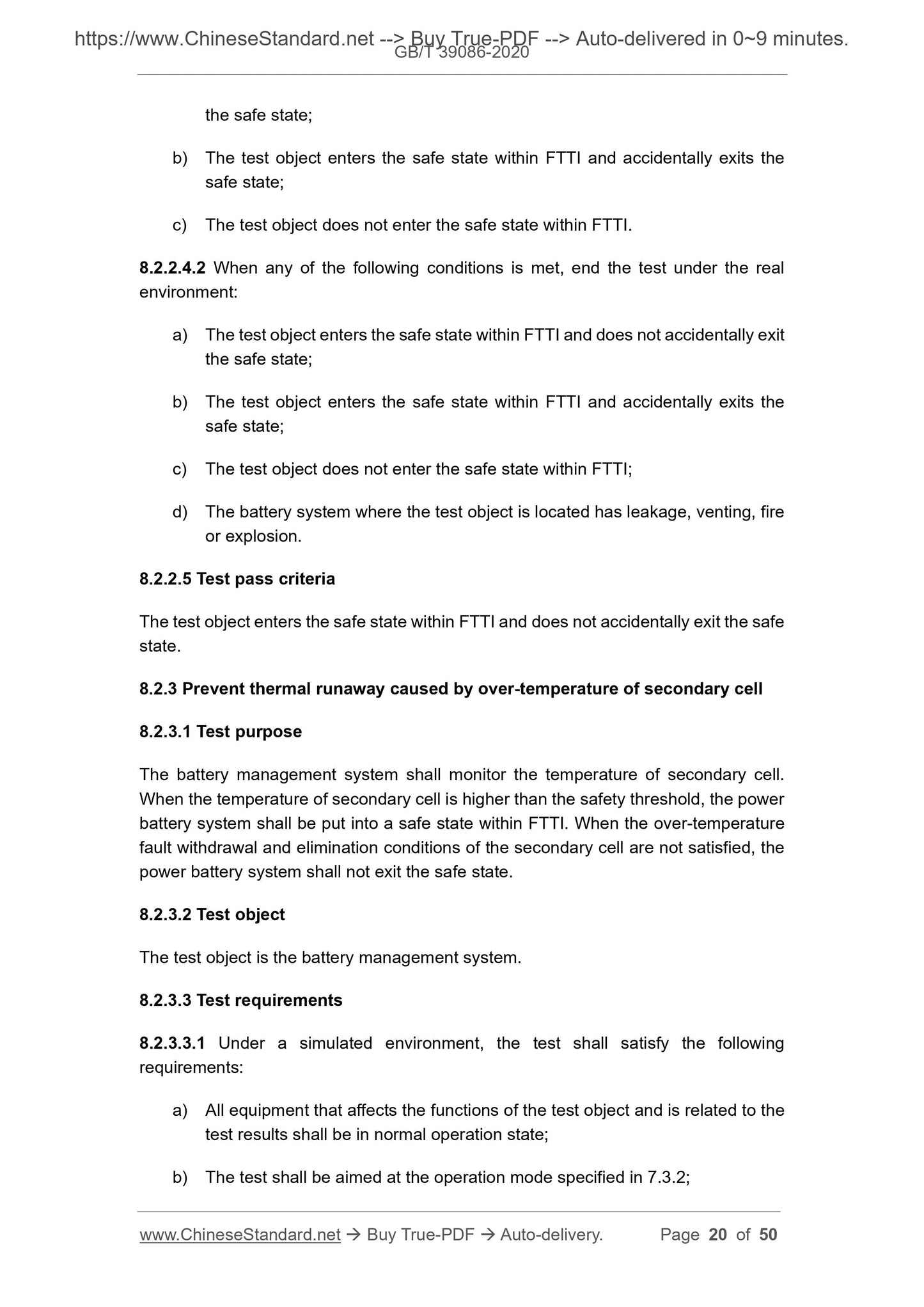
the safe state;
b) The test object enters the safe state within FTTI and accidentally exits the
safe state;
c) The test object does not enter the safe state within FTTI.
8.2.2.4.2 When any of the following conditions is met, end the test under the real
environment:
a) The test object enters the safe state within FTTI and does not accidentally exit
the safe state;
b) The test object enters the safe state within FTTI and accidentally exits the
safe state;
c) The test object does not enter the safe state within FTTI;
d) The battery system where the test object is located has leakage, venting, fire
or explosion.
8.2.2.5 Test pass criteria
The test object enters the safe state within FTTI and does not accidentally exit the safe
state.
8.2.3 Prevent thermal runaway caused by over-temperature of secondary cell
8.2.3.1 Test purpose
The battery management system shall monitor the temperature of secondary cell.
When the temperature of secondary cell is higher than the safety threshold, the power
battery system shall be put into a safe state within FTTI. When the over-temperature
fault withdrawal and elimination conditions of the secondary cell are not satisfied, the
power battery system shall not exit the safe state.
8.2.3.2 Test object
The test object is the battery management system.
8.2.3.3 Test requirements
8.2.3.3.1 Under a simulated environment, the test shall satisfy the following
requirements:
a) All equipment that affects the functions of the test object and is related to the
test results shall be in normal operation state;
b) The test shall be aimed at the operation mode specified in 7.3.2;
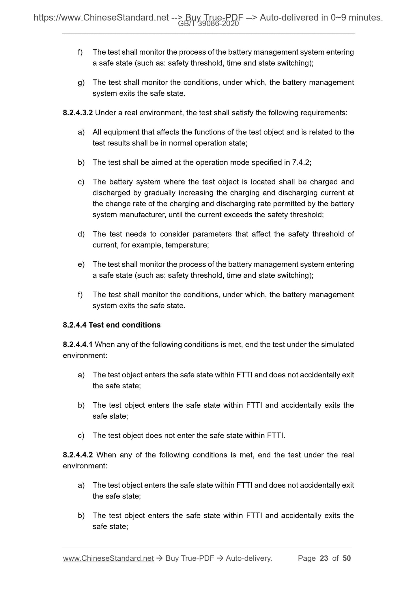
f) The test shall monitor the process of the battery management system entering
a safe state (such as: safety threshold, time and state switching);
g) The test shall monitor the conditions, under which, the battery management
system exits the safe state.
8.2.4.3.2 Under a real environment, the test shall satisfy th...
Share