PayPal, credit cards. Download editable-PDF & invoice in 1 second!
GB/T 38712-2020 English PDF (GBT38712-2020)
Couldn't load pickup availability
GB/T 38712-2020: Test method for thermal conductivity of ultrathin glass -- Heat flow method
NATIONAL STANDARD OF THE
PEOPLE’S REPUBLIC OF CHINA
ICS 81.040.01
Q 34
Test method for thermal conductivity of ultrathin glass
- Heat flow method
ISSUED ON: MARCH 31, 2020
IMPLEMENTED ON: FEBRUARY 01, 2021
Issued by: State Administration for Market Regulation;
Standardization Administration of the People’s Republic of
China.
Table of Contents
Foreword ... 3
1 Scope ... 4
2 Normative references ... 4
3 Terms and definitions ... 4
4 Test device ... 5
5 Environmental conditions ... 6
6 Sample requirements ... 6
7 Test steps ... 7
8 Result calculation and expression ... 8
9 Instrument calibration ... 9
10 Test report ... 9
Test method for thermal conductivity of ultrathin glass
- Heat flow method
1 Scope
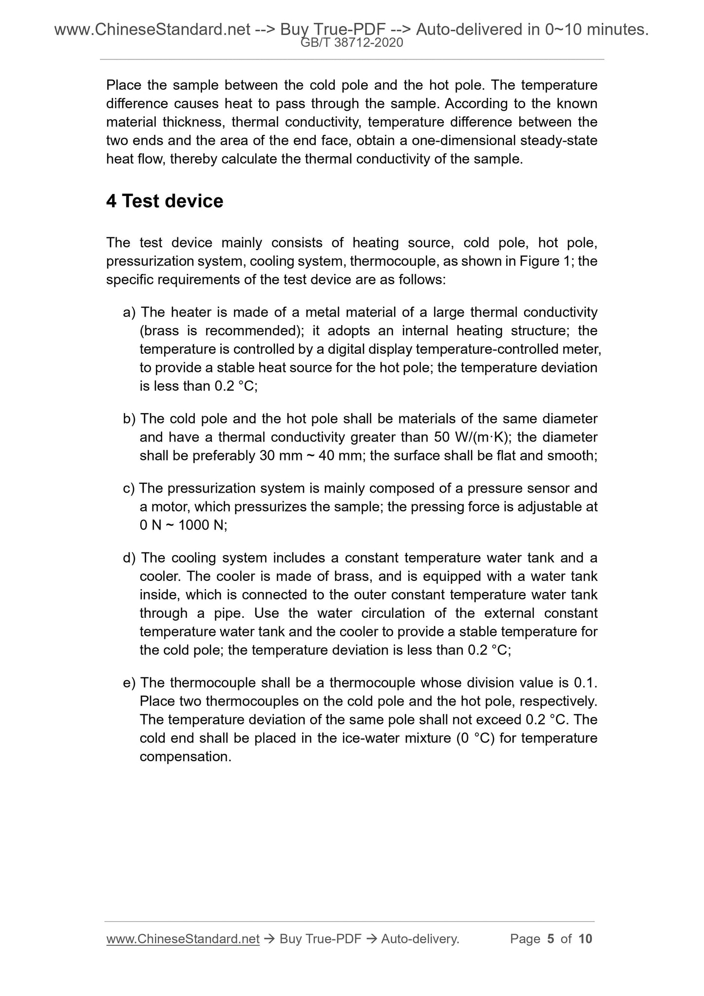
This Standard specifies the terms and definitions, test device, environmental conditions, sample requirements, test steps, result calculation and expression, instrument calibration, and test reports for measuring the thermal conductivity of ultrathin glass by the heat flow method.
This Standard applies to the test of the thermal conductivity of ultrathin glass. 2 Normative references
The following documents are indispensable for the application of this document. For dated references, only the dated version applies to this document. For undated references, the latest edition (including all amendments) applies to this document.
GB/T 5598, Test method for thermal conductivity of beryllium oxide ceramics GB/T 21389, Vernier, dial and digital display calipers
GB/T 34171, Test method for flexural property of thin and ultrathin glass - Three-point bending method
3 Terms and definitions
Terms and definitions determined by GB/T 5598, GB/T 34171 and the following ones are applicable to this document.
3.1 Ultrathin glass
Plate glass products whose thickness is not greater than 1.1 mm.
3.2 Thermal conductivity
On the unit area, the steady-state heat flow rate that is caused by the unit temperature gradient perpendicular to this direction. Under steady-state heat conduction conditions, the density of heat flow is divided by the temperature gradient.
3.3 Heat flow method
Place the sample between the cold pole and the hot pole. The temperature difference causes heat to pass through the sample. According to the known material thickness, thermal conductivity, temperature difference between the two ends and the area of the end face, obtain a one-dimensional steady-state heat flow, thereby calculate the thermal conductivity of the sample.
4 Test device
The test device mainly consists of heating source, cold pole, hot pole, pressurization system, cooling system, thermocouple, as shown in Figure 1; the specific requirements of the test device are as follows:
a) The heater is made of a metal material of a large thermal conductivity (brass is recommended); it adopts an internal heating structure; the
temperature is controlled by a digital display temperature-controlled meter, to provide a stable heat source for the hot pole; the temperature deviation is less than 0.2 °C;
b) The cold pole and the hot pole shall be materials of the same diameter and have a thermal conductivity greater than 50 W/(m·K); the diameter
shall be preferably 30 mm ~ 40 mm; the surface shall be flat and smooth; c) The pressurization system is mainly composed of a pressure sensor and a motor, which pressurizes the sample; the pressing force is adjustable at 0 N ~ 1000 N;
d) The cooling system includes a constant temperature water tank and a
cooler. The cooler is made of brass, and is equipped with a water tank
inside, which is connected to the outer constant temperature water tank through a pipe. Use the water circulation of the external constant
temperature water tank and the cooler to provide a stable temperature for the cold pole; the temperature deviation is less than 0.2 °C;
e) The thermocouple shall be a thermocouple whose division value is 0.1. Place two thermocouples on the cold pole and the hot pole, respectively. The temperature deviation of the same pole shall not exceed 0.2 °C. The cold end shall be placed in the ice-water mixture (0 °C) for temperature compensation.
b) Use a Vernier caliper that meets the requirements of GB/T 21389 to
measure the thickness of the glass pieces; calculate the number of glass pieces whose stack thickness is greater than 2 mm;
c) Wash and dry the small glass pieces; ensure that the surface is clean; d) Use thermal silicone grease whose thermal conductivity is greater than 1.5 W/(m·K); bond and overlay the cleaned glass pieces; the thermal
silicon grease between the glass pieces shall be applied evenly;
e) Use a pressure that is not less than 200 N to compact the superimposed samples; then, wipe off the thermal silicone grease that overflows the
edge of the sample;
f) Use a Vernier caliper that meets the requirements of GB/T 21389 to
measure the thickness of the compacted sample; measure it three times
at 120° rotation; take the average value, and record it as d. It is required that the thickness of the thermal silicon grease between the glass
laminations is not more than 20% of the thickness d of the sample.
6.2 Number of samples
The number of samples is 3.
7 Test steps
7.1 Test preparation
The test preparation steps are as follows:
a) Insert the cold ends of all thermocouples into the ice-water mixture (0 °C) to compensate for the cold end temperature;
b) Set the cold pole temperature to (20 ± 5) °C;
c) Set the hot pole temperature; the hot pole temperature shall be 40 °C greater than the cold pole temperature.
7.2 Sample placement
Apply thermal silicon grease whose thermal conductivity is not less than 1.5 W/(m·K) on the upper and lower sides of the sample; the total thickness of the thermal silicon grease on the upper and lower sides of the sample is not more than 0.1 mm; then, place it between the cold and hot poles.
7.3 Sample test
Share