1
/
of
8
www.ChineseStandard.us -- Field Test Asia Pte. Ltd.
GB/T 38684-2020 English PDF (GB/T38684-2020)
GB/T 38684-2020 English PDF (GB/T38684-2020)
Regular price
$255.00
Regular price
Sale price
$255.00
Unit price
/
per
Shipping calculated at checkout.
Couldn't load pickup availability
GB/T 38684-2020: Metallic materials - Sheet and strip - Biaxial stress-strain curve by means of bulge test - Optical measuring systems
Delivery: 9 seconds. Download (and Email) true-PDF + Invoice.Get Quotation: Click GB/T 38684-2020 (Self-service in 1-minute)
Newer / historical versions: GB/T 38684-2020
Preview True-PDF
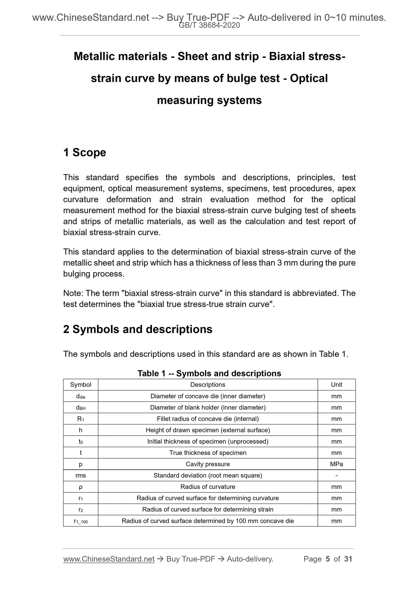
Scope
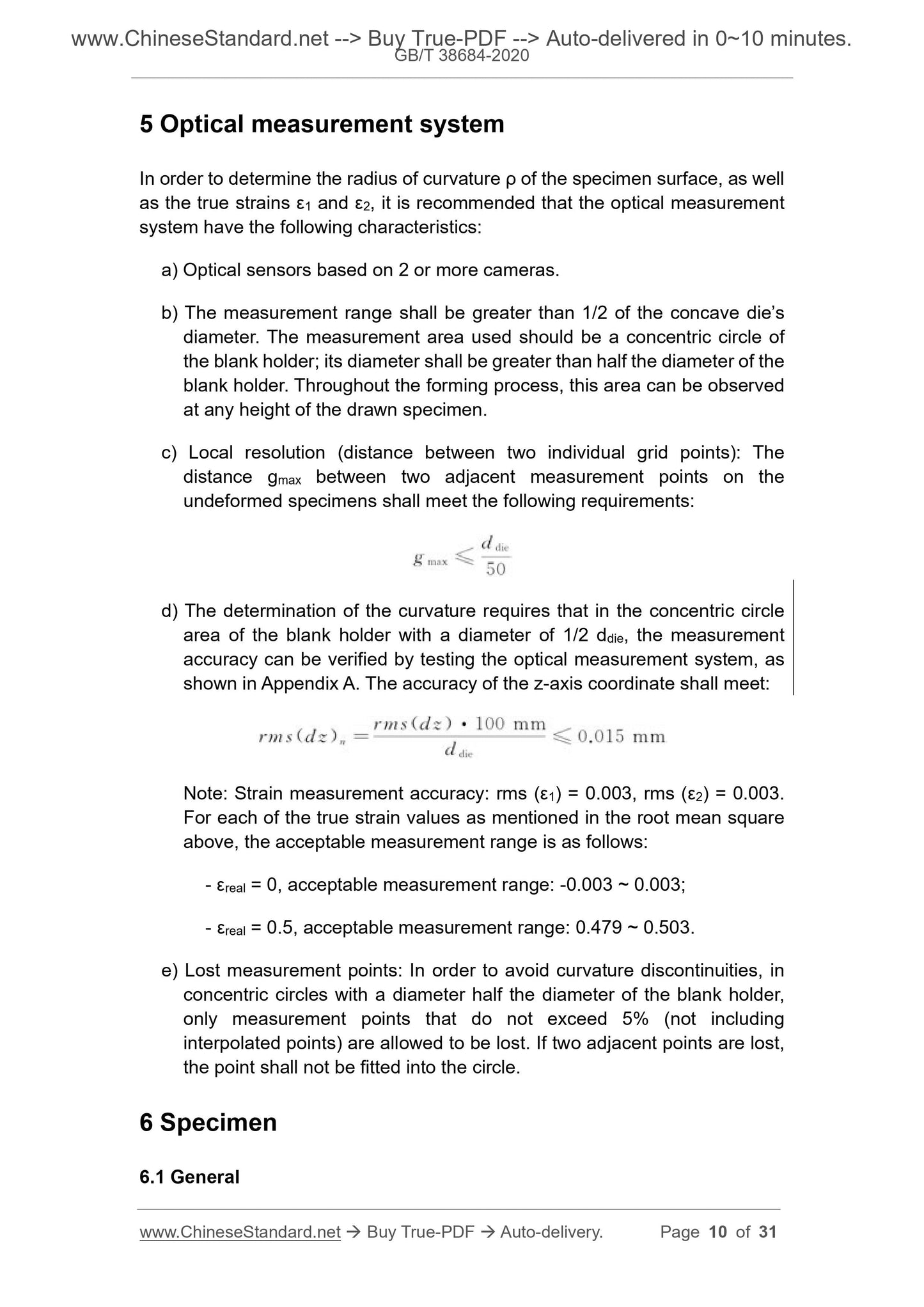
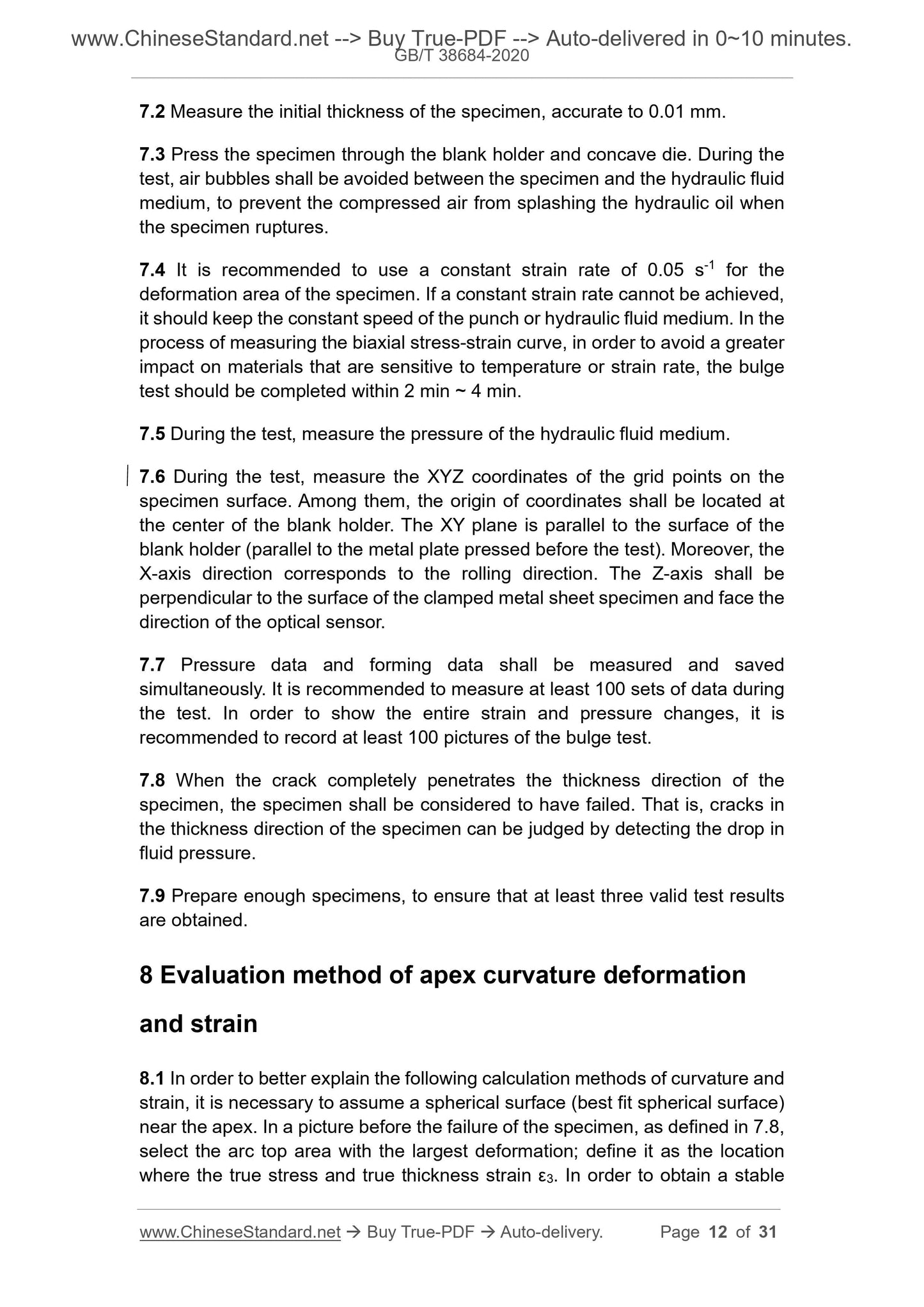
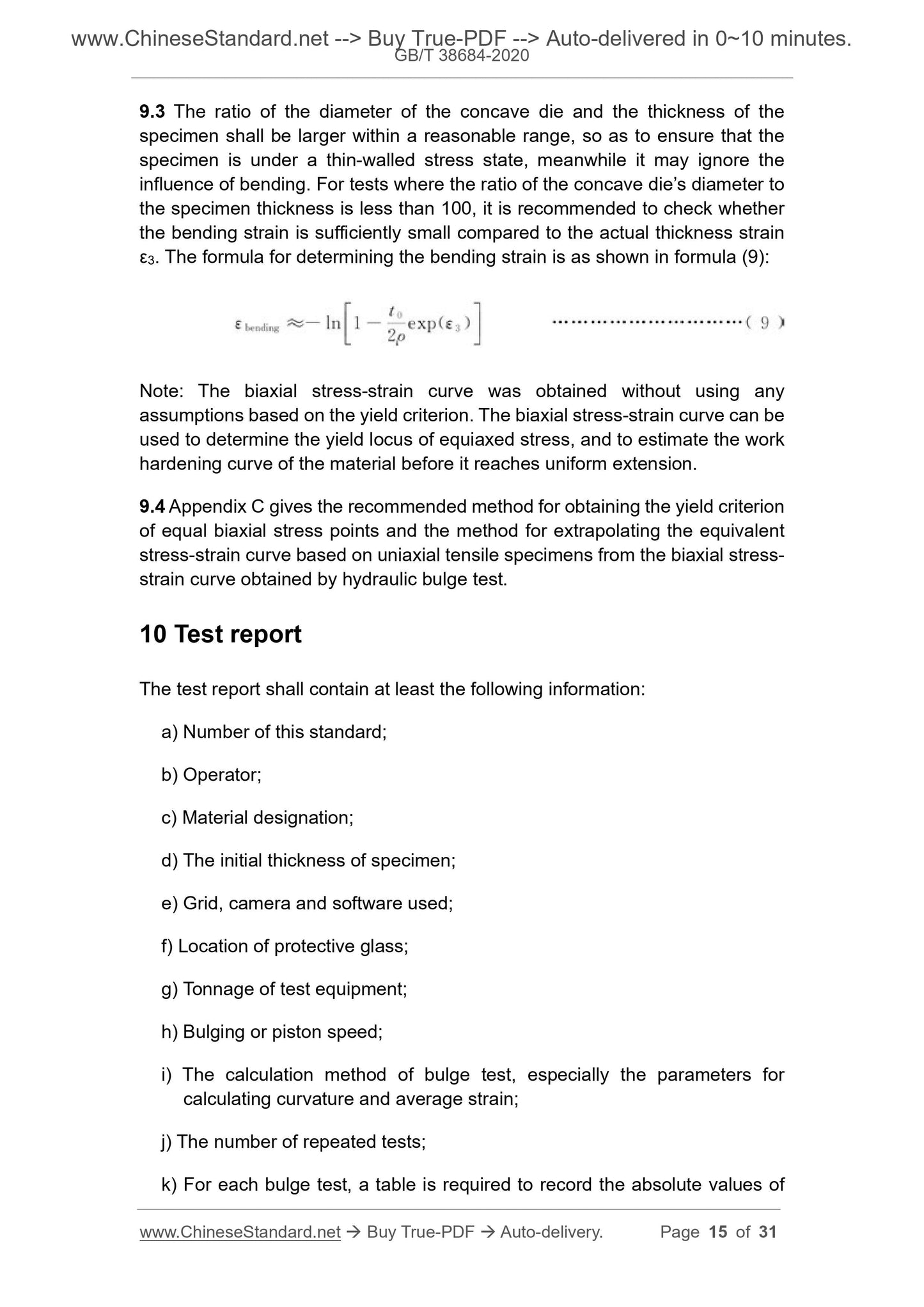
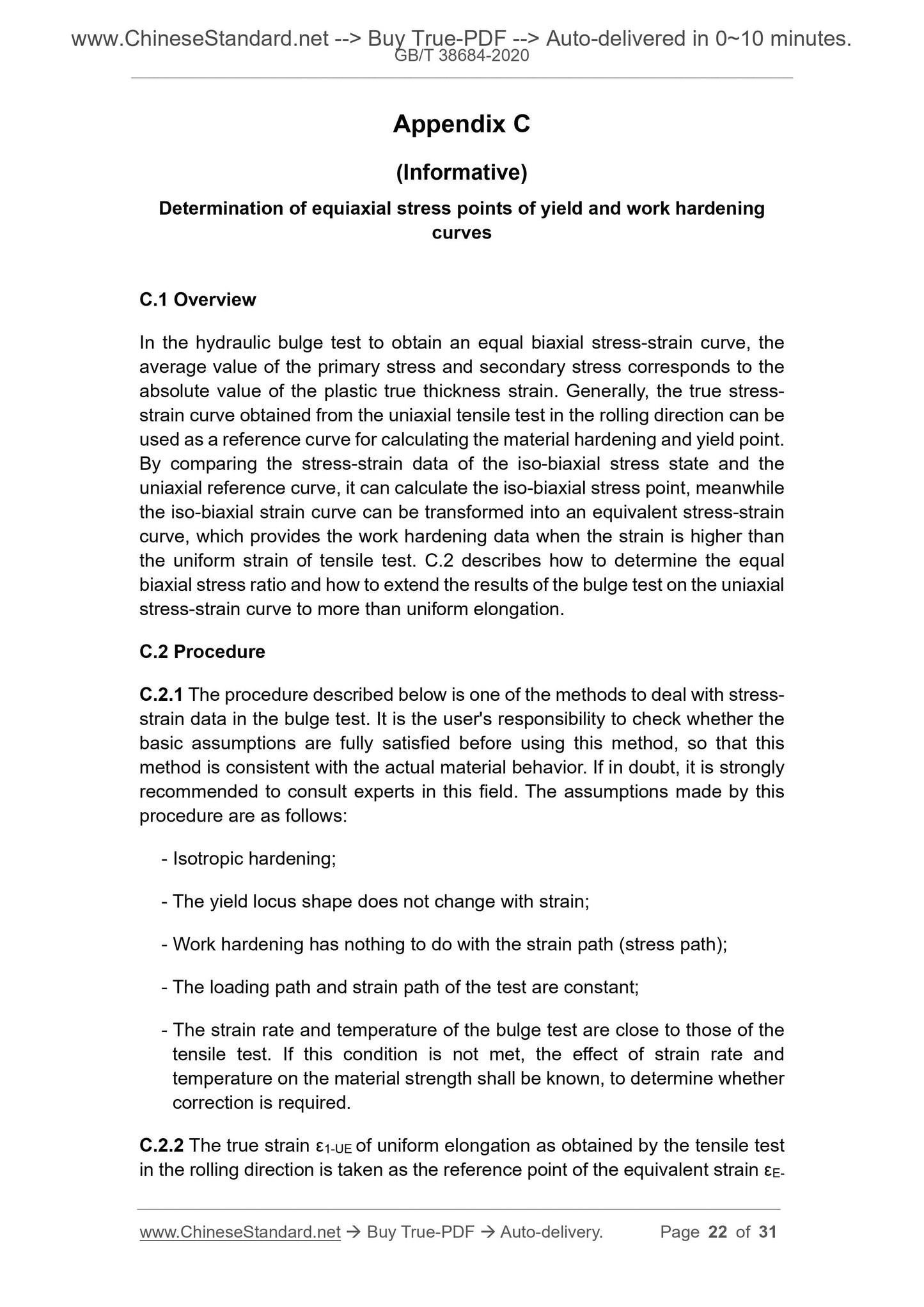
This standard specifies the symbols and descriptions, principles, testequipment, optical measurement systems, specimens, test procedures, apex
curvature deformation and strain evaluation method for the optical
measurement method for the biaxial stress-strain curve bulging test of sheets
and strips of metallic materials, as well as the calculation and test report of
biaxial stress-strain curve.
This standard applies to the determination of biaxial stress-strain curve of the
metallic sheet and strip which has a thickness of less than 3 mm during the pure
bulging process.
Note: The term "biaxial stress-strain curve" in this standard is abbreviated. The
test determines the "biaxial true stress-true strain curve".
Basic Data
| Standard ID | GB/T 38684-2020 (GB/T38684-2020) |
| Description (Translated English) | Metallic materials - Sheet and strip - Biaxial stress-strain curve by means of bulge test - Optical measuring systems |
| Sector / Industry | National Standard (Recommended) |
| Classification of Chinese Standard | H22 |
| Classification of International Standard | 77.040.10 |
| Word Count Estimation | 22,262 |
| Date of Issue | 2020-03-31 |
| Date of Implementation | 2020-10-01 |
| Adopted Standard | ISO 16808-2014, MOD |
| Issuing agency(ies) | State Administration for Market Regulation, China National Standardization Administration |
| Summary | This standard specifies the symbols and descriptions, principles, test equipment, optical measurement systems, test specimens, test procedures, evaluation of vertex curvature deformation and strain of optical measurement methods for biaxial stress-strain curve bulging tests of metal sheets and strips Methods, calculations of biaxial stress-strain curves and test reports. This standard applies to metal sheets and strips with a thickness of less than 3 mm, whose biaxial stress-strain curves are determined during pure bulging. Note: The term "biaxial stress-strain curve" in this standard is abbreviated. What the test measures is a "biaxial true stress-true strain curve". |
Share