1
/
of
5
www.ChineseStandard.us -- Field Test Asia Pte. Ltd.
GB/T 38039-2019 English PDF (GB/T38039-2019)
Regular price
$100.00
Regular price
Sale price
$100.00
Unit price
/
per
Shipping calculated at checkout.
Couldn't load pickup availability
GB/T 38039-2019: Footwear - Test methods for slide fasteners - Resistance to damage during closure under a lateral force
Delivery: 9 seconds. Download (& Email) true-PDF + Invoice.
Get Quotation: Click GB/T 38039-2019 (Self-service in 1-minute)
Historical versions (Master-website): GB/T 38039-2019
Preview True-PDF (Reload/Scroll-down if blank)
GB/T 38039-2019
GB
NATIONAL STANDARD OF THE
PEOPLE’S REPUBLIC OF CHINA
ICS 61.060
Y 78
GB/T 38039-2019 / ISO 18403:2016
Footwear - Test methods for slide fasteners -
Resistance to damage during closure under a lateral
force
(ISO 18403:2016, IDT)
ISSUED ON: OCTOBER 18, 2019
IMPLEMENTED ON: MAY 01, 2020
Issued by: State Administration for Market Regulation;
Standardization Administration of the People's Republic of
China.
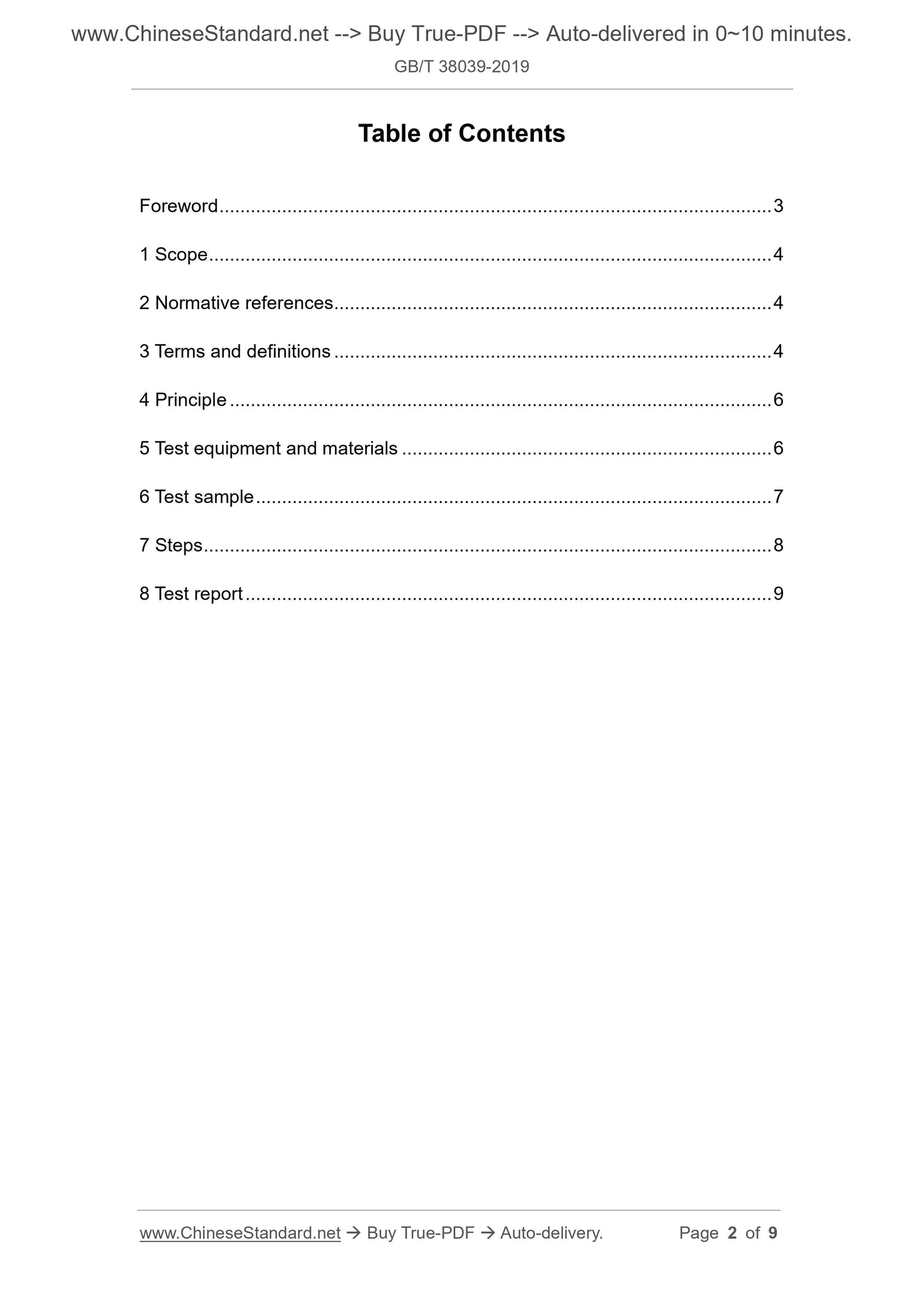
Table of Contents
Foreword ... 3
1 Scope ... 4
2 Normative references ... 4
3 Terms and definitions ... 4
4 Principle ... 6
5 Test equipment and materials ... 6
6 Test sample ... 7
7 Steps ... 8
8 Test report ... 9
Footwear - Test methods for slide fasteners -
Resistance to damage during closure under a lateral
force
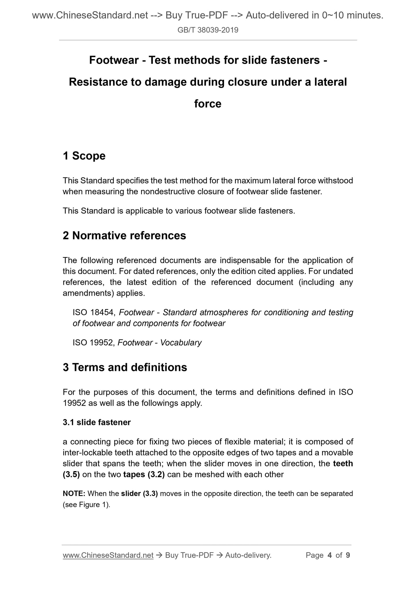
1 Scope
This Standard specifies the test method for the maximum lateral force withstood
when measuring the nondestructive closure of footwear slide fastener.
This Standard is applicable to various footwear slide fasteners.
2 Normative references
The following referenced documents are indispensable for the application of
this document. For dated references, only the edition cited applies. For undated
references, the latest edition of the referenced document (including any
amendments) applies.
ISO 18454, Footwear - Standard atmospheres for conditioning and testing
of footwear and components for footwear
ISO 19952, Footwear - Vocabulary
3 Terms and definitions
For the purposes of this document, the terms and definitions defined in ISO
19952 as well as the followings apply.
3.1 slide fastener
a connecting piece for fixing two pieces of flexible material; it is composed of
inter-lockable teeth attached to the opposite edges of two tapes and a movable
slider that spans the teeth; when the slider moves in one direction, the teeth
(3.5) on the two tapes (3.2) can be meshed with each other
NOTE: When the slider (3.3) moves in the opposite direction, the teeth can be separated
(see Figure 1).
teeth
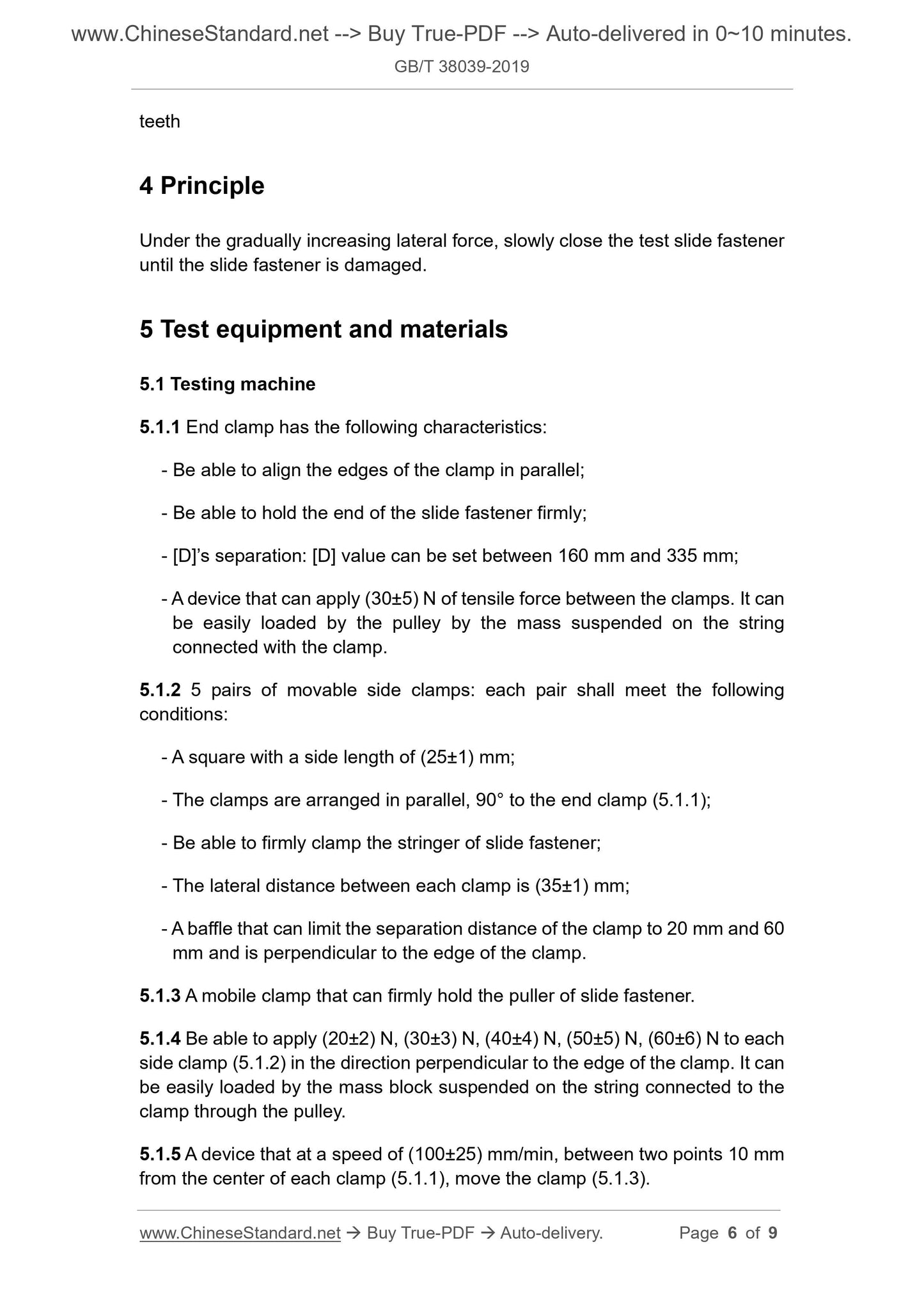
4 Principle
Under the gradually increasing lateral force, slowly close the test slide fastener
until the slide fastener is damaged.
5 Test equipment and materials
5.1 Testing machine
5.1.1 End clamp has the following characteristics:
- Be able to align the edges of the clamp in parallel;
- Be able to hold the end of the slide fastener firmly;
- [D]’s separation: [D] value can be set between 160 mm and 335 mm;
- A device that can apply (30±5) N of tensile force between the clamps. It can
be easily loaded by the pulley by the mass suspended on the string
connected with the clamp.
5.1.2 5 pairs of movable side clamps: each pair shall meet the following
conditions:
- A square with a side length of (25±1) mm;
- The clamps are arranged in parallel, 90° to the end clamp (5.1.1);
- Be able to firmly clamp the stringer of slide fastener;
- The lateral distance between each clamp is (35±1) mm;
- A baffle that can limit the separation distance of the clamp to 20 mm and 60
mm and is perpendicular to the edge of the clamp.
5.1.3 A mobile clamp that can firmly hold the puller of slide fastener.
5.1.4 Be able to apply (20±2) N, (30±3) N, (40±4) N, (50±5) N, (60±6) N to each
side clamp (5.1.2) in the direction perpendicular to the edge of the clamp. It can
be easily loaded by the mass block suspended on the string connected to the
clamp through the pulley.
5.1.5 A device that at a speed of (100±25) mm/min, between two points 10 mm
from the center of each clamp (5.1.1), move the clamp (5.1.3).
7 Steps
7.1 Pull the test slide fastener closed. Clamp the end of the slide fastener in
each stop end clamp (5.1.1). Ensure that the length of the slide fastener
clamped in each clamp is similar. At the same time, make the slide fastener part
between the clamps as long as possible. But the longest does not exceed 335
mm.
7.2 At the stop end clamp (5.1.1), apply a longitudinal force of (30±5) N to
stretch the test slide fastener. Fix the stop end clamp in this position. Maintain
the expected tension.
7.3 On each stringer, at (50±5) mm from the edge of the clamp that clamps the
end of the test slide fastener, draw a parallel line, which shall be the test point
1.
7.4 From the test point 1, along the length direction of the test slide fastener, at
every interval (60±5) mm on two stringers, draw parallel lines of the marking
line (7.3). The position where it is less than 45 mm from the edge of the stop
end clamp holding the upper end of the slide fastener is not marked with lines.
Each marking line is the test point.
7.5 At each test point of each stringer, clamp a side clamp (5.1.2). It can be:
- The distance between the clamps at each test point is (20±2) mm;
- The marking line of the stringer is 90° from the edge of the clamp. It is
located in the center of the edge of the clamp.
7.6 Move the slider to open the test slide fastener until the distance between
the slider and the edge of the clamp (5.1.1) holding the bottom of the slide
fastener is (10±2) mm. Clamp the puller with clamps (5.1.3).
7.7 On each side clamp at test point 1, apply a force of (20±2) N. That is, apply
a lateral force to the slide fastener.
7.8 At a speed of (100±25) mm/min, move the clamp (5.1.3) to make the test
slide fastener to gradually close. Stop when the clamp (5.1.3) moves about 60
mm on the slide fastener. That is, it just passes the side clamp that is applied
with a lateral force.
7.9 If the slide fastener is successfully closed without damage, then apply (30±3)
N of lateral force on each clamp of the next pair of side clamps (5.1.2). Repeat
the step of 7.8.
7.10 Repeat the steps of 7.8 and 7.9. At the remaining test points, respectively
Share