1
/
of
5
www.ChineseStandard.us -- Field Test Asia Pte. Ltd.
GB/T 37825-2019 English PDF (GB/T37825-2019)
GB/T 37825-2019 English PDF (GB/T37825-2019)
Regular price
$230.00
Regular price
Sale price
$230.00
Unit price
/
per
Shipping calculated at checkout.
Couldn't load pickup availability
GB/T 37825-2019: Test method for simulating wind pressure resistance of building glass under the uniform static loads
Delivery: 9 seconds. Download (and Email) true-PDF + Invoice.Get Quotation: Click GB/T 37825-2019 (Self-service in 1-minute)
Newer / historical versions: GB/T 37825-2019
Preview True-PDF
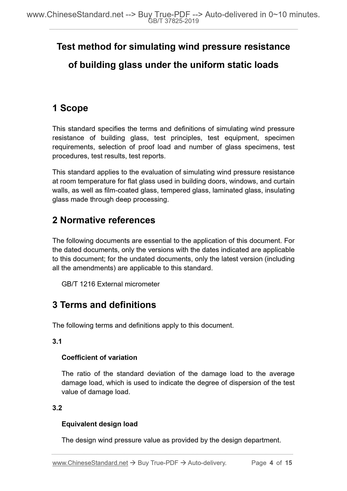
Scope
This standard specifies the terms and definitions of simulating wind pressureresistance of building glass, test principles, test equipment, specimen
requirements, selection of proof load and number of glass specimens, test
procedures, test results, test reports.
This standard applies to the evaluation of simulating wind pressure resistance
at room temperature for flat glass used in building doors, windows, and curtain
walls, as well as film-coated glass, tempered glass, laminated glass, insulating
glass made through deep processing.
Basic Data
| Standard ID | GB/T 37825-2019 (GB/T37825-2019) |
| Description (Translated English) | Test method for simulating wind pressure resistance of building glass under the uniform static loads |
| Sector / Industry | National Standard (Recommended) |
| Classification of Chinese Standard | Q33 |
| Classification of International Standard | 81.040.20 |
| Word Count Estimation | 14,120 |
| Date of Issue | 2019-08-30 |
| Date of Implementation | 2020-07-01 |
| Issuing agency(ies) | State Administration for Market Regulation, China National Standardization Administration |
Share