Skip to product information
1 of 8

www.ChineseStandard.us -- Field Test Asia Pte. Ltd.

GB/T 37706-2019 English PDF (GB/T37706-2019)

GB/T 37706-2019 English PDF (GB/T37706-2019)

Regular price $190.00
Regular price Sale price $190.00
Sale Sold out
Shipping calculated at checkout.
GB/T 37706-2019: Installation and Operation Technical Requirements of Tail Lifts for Vehicle
Delivery: 9 seconds. Download (& Email) true-PDF + Invoice.
Get Quotation: Click GB/T 37706-2019 (Self-service in 1-minute)
Historical versions (Master-website): GB/T 37706-2019
Preview True-PDF (Reload/Scroll-down if blank)

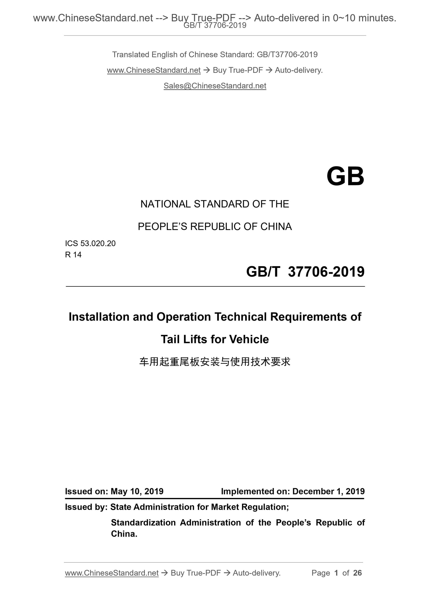
GB/T 37706-2019
NATIONAL STANDARD OF THE
PEOPLE’S REPUBLIC OF CHINA
ICS 53.020.20
R 14
Installation and Operation Technical Requirements of
Tail Lifts for Vehicle
ISSUED ON: MAY 10, 2019
IMPLEMENTED ON: DECEMBER 1, 2019
Issued by: State Administration for Market Regulation;
Standardization Administration of the People’s Republic of
China.
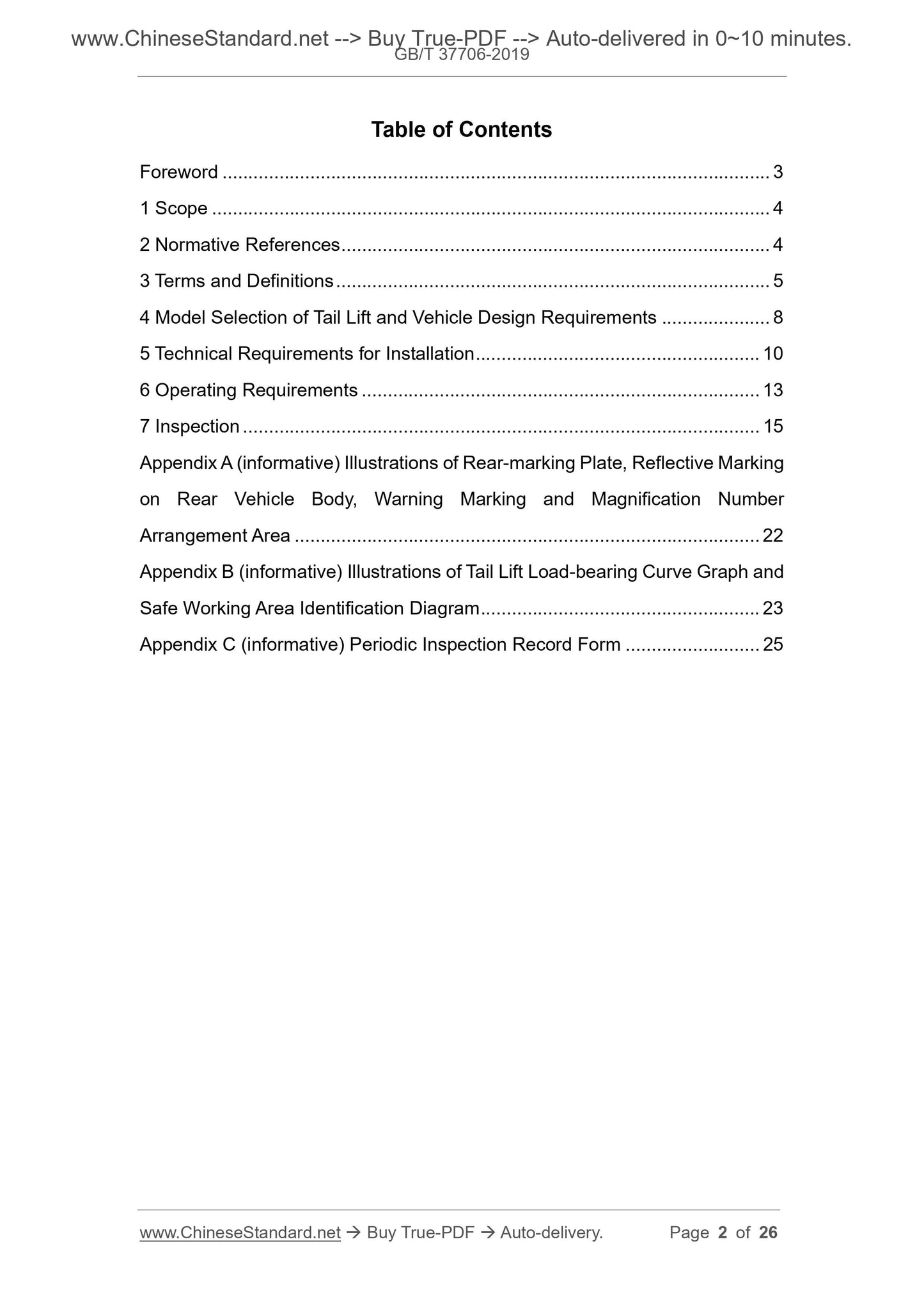
Table of Contents
Foreword ... 3 
1 Scope ... 4 
2 Normative References ... 4 
3 Terms and Definitions ... 5 
4 Model Selection of Tail Lift and Vehicle Design Requirements ... 8 
5 Technical Requirements for Installation ... 10 
6 Operating Requirements ... 13 
7 Inspection ... 15 
Appendix A (informative) Illustrations of Rear-marking Plate, Reflective Marking
on Rear Vehicle Body, Warning Marking and Magnification Number
Arrangement Area ... 22 
Appendix B (informative) Illustrations of Tail Lift Load-bearing Curve Graph and
Safe Working Area Identification Diagram ... 23 
Appendix C (informative) Periodic Inspection Record Form ... 25 
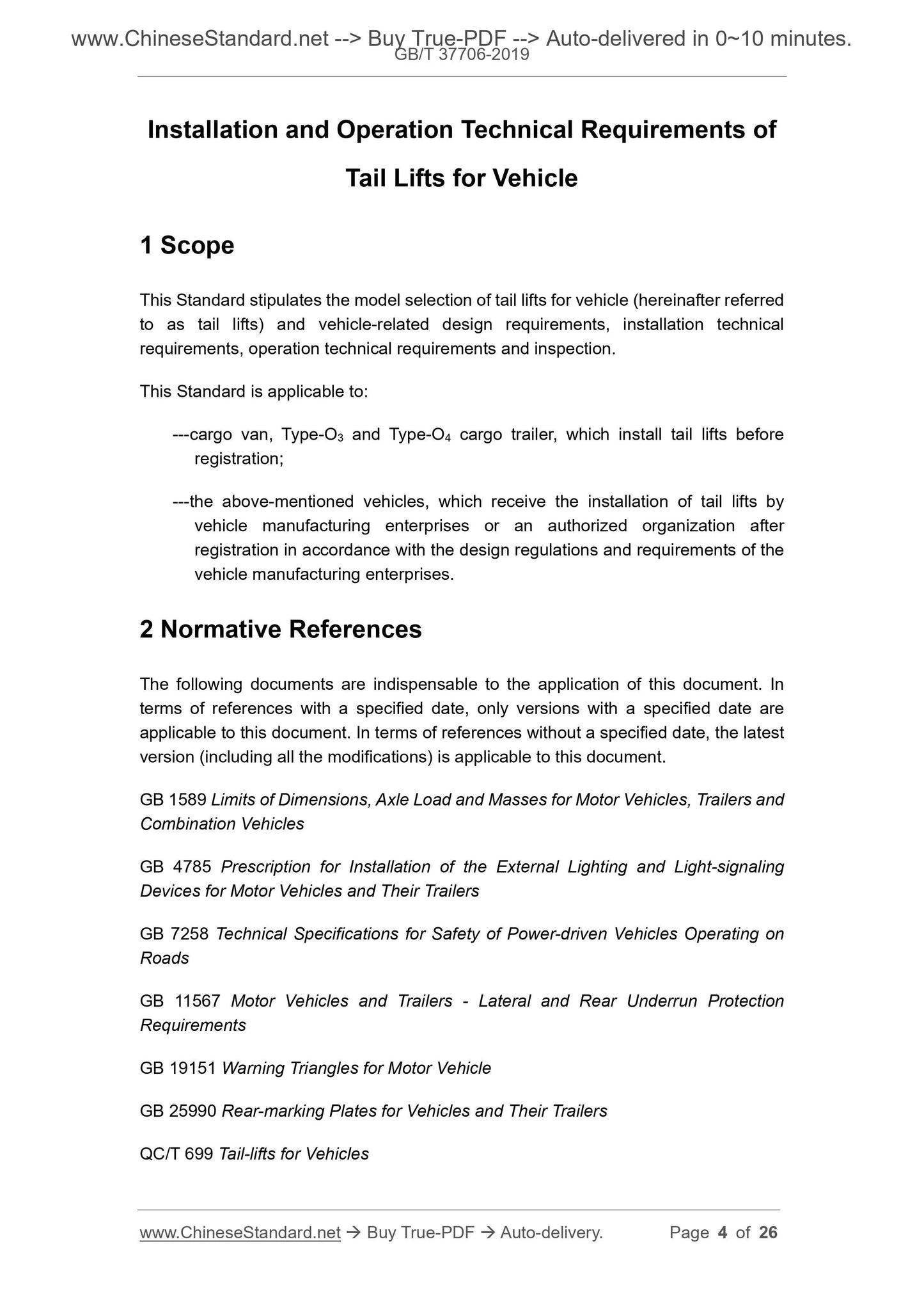
Installation and Operation Technical Requirements of
Tail Lifts for Vehicle
1 Scope
This Standard stipulates the model selection of tail lifts for vehicle (hereinafter referred
to as tail lifts) and vehicle-related design requirements, installation technical
requirements, operation technical requirements and inspection.
This Standard is applicable to:
---cargo van, Type-O3 and Type-O4 cargo trailer, which install tail lifts before
registration;
---the above-mentioned vehicles, which receive the installation of tail lifts by
vehicle manufacturing enterprises or an authorized organization after
registration in accordance with the design regulations and requirements of the
vehicle manufacturing enterprises.
2 Normative References
The following documents are indispensable to the application of this document. In
terms of references with a specified date, only versions with a specified date are
applicable to this document. In terms of references without a specified date, the latest
version (including all the modifications) is applicable to this document.
GB 1589 Limits of Dimensions, Axle Load and Masses for Motor Vehicles, Trailers and
Combination Vehicles
GB 4785 Prescription for Installation of the External Lighting and Light-signaling
Devices for Motor Vehicles and Their Trailers
GB 7258 Technical Specifications for Safety of Power-driven Vehicles Operating on
Roads
GB 11567 Motor Vehicles and Trailers - Lateral and Rear Underrun Protection
Requirements
GB 19151 Warning Triangles for Motor Vehicle
GB 25990 Rear-marking Plates for Vehicles and Their Trailers
QC/T 699 Tail-lifts for Vehicles
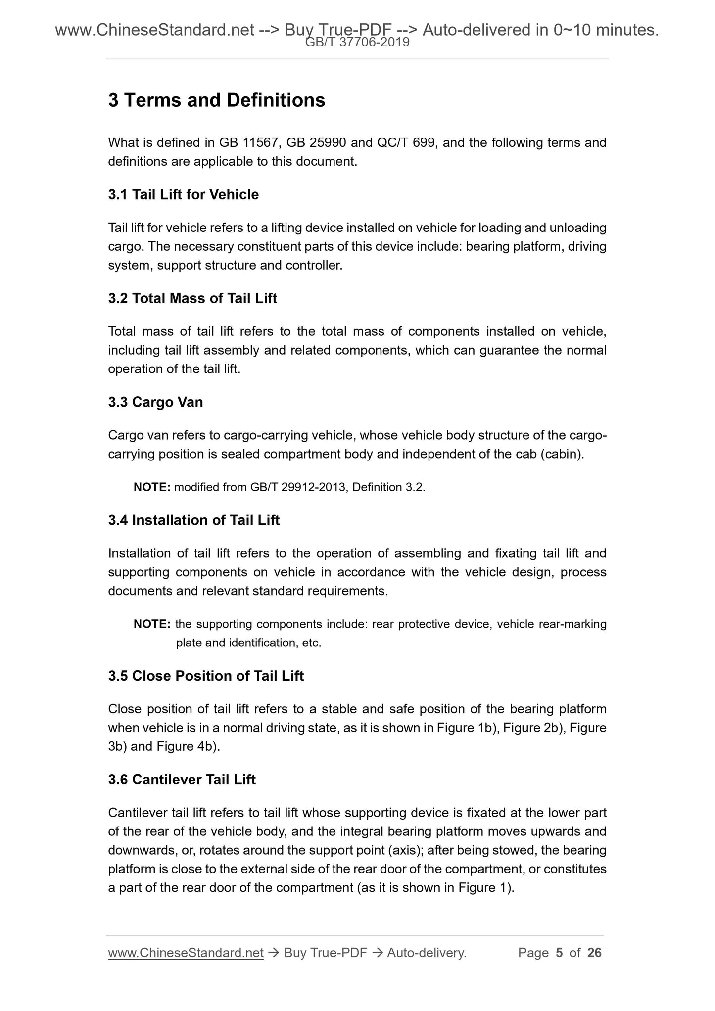
3 Terms and Definitions
What is defined in GB 11567, GB 25990 and QC/T 699, and the following terms and
definitions are applicable to this document.
3.1 Tail Lift for Vehicle
Tail lift for vehicle refers to a lifting device installed on vehicle for loading and unloading
cargo. The necessary constituent parts of this device include: bearing platform, driving
system, support structure and controller.
3.2 Total Mass of Tail Lift
Total mass of tail lift refers to the total mass of components installed on vehicle,
including tail lift assembly and related components, which can guarantee the normal
operation of the tail lift.
3.3 Cargo Van
Cargo van refers to cargo-carrying vehicle, whose vehicle body structure of the cargo-
carrying position is sealed compartment body and independent of the cab (cabin).
NOTE: modified from GB/T 29912-2013, Definition 3.2.
3.4 Installation of Tail Lift
Installation of tail lift refers to the operation of assembling and fixating tail lift and
supporting components on vehicle in accordance with the vehicle design, process
documents and relevant standard requirements.
NOTE: the supporting components include: rear protective device, vehicle rear-marking
plate and identification, etc.
3.5 Close Position of Tail Lift
Close position of tail lift refers to a stable and safe position of the bearing platform
when vehicle is in a normal driving state, as it is shown in Figure 1b), Figure 2b), Figure
3b) and Figure 4b).
3.6 Cantilever Tail Lift
Cantilever tail lift refers to tail lift whose supporting device is fixated at the lower part
of the rear of the vehicle body, and the integral bearing platform moves upwards and
downwards, or, rotates around the support point (axis); after being stowed, the bearing
platform is close to the external side of the rear door of the compartment, or constitutes
a part of the rear door of the compartment (as it is shown in Figure 1).
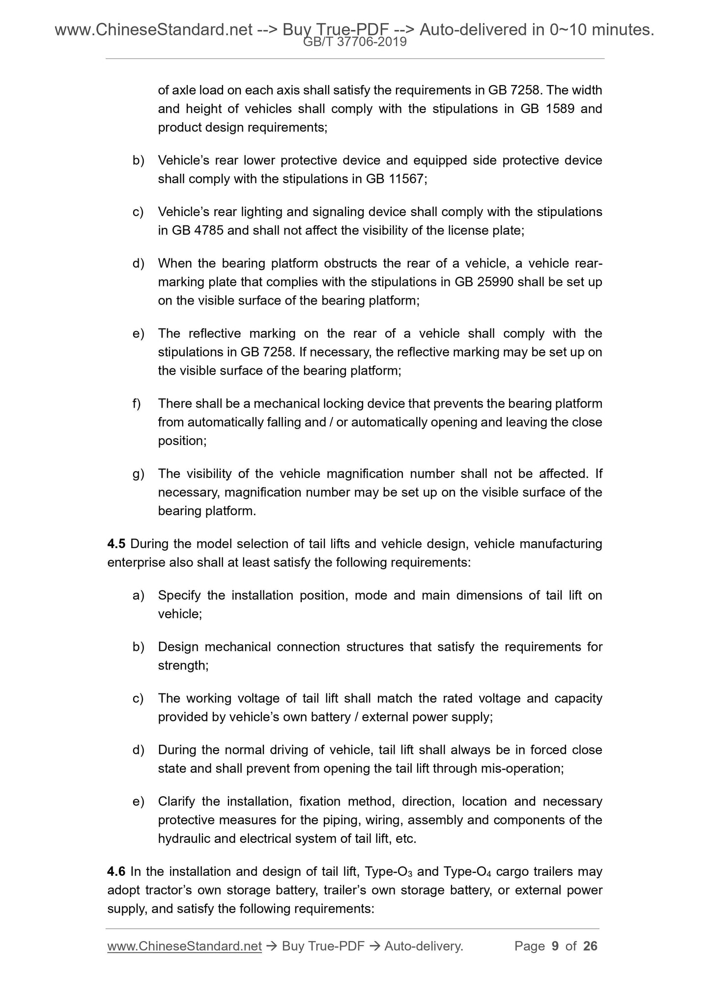
of axle load on each axis shall satisfy the requirements in GB 7258. The width
and height of vehicles shall comply with the stipulations in GB 1589 and
product design requirements;
b) Vehicle’s rear lower protective device and equipped side protective device
shall comply with the stipulations in GB 11567;
c) Vehicle’s rear lighting and signaling device shall comply with the stipulations
in GB 4785 and shall not affect the visibility of the license plate;
d) When the bearing platform obstructs the rear of a vehicle, a vehicle rear-
marking plate that complies with the stipulations in GB 25990 shall be set up
on the visible surface of the bearing platform;
e) The reflective marking on the rear of a vehicle shall comply with the
stipulations in GB 7258. If necessary, the reflective marking may be set up on
the visible surface of the bearing platform;
f) There shall be a mechanical locking device that prevents the bearing platform
from automatically falling and / or automatically opening and leaving the close
position;
g) The visibility of the vehicle magnification number shall not be affected. If
necessary, magnification number may be set up on the visible surface of the
bearing platform.
4.5 During the model selection of tail lifts and vehicle design, vehicle manufacturing
enterprise also shall at least satisfy the following requirements:
a) Specify the installation position, mode and main dimensions of tail lift on
vehicle;
b) Design mechanical connection structures that satisfy the requirements for
strength;
c) The working voltage of tail lift shall match the rated voltage and capacity
provided by vehicle’s own battery / external power supply;
d) During the normal driving of vehicle, tail lift shall always be in forced close
state and shall prevent from opening the tail lift through mis-operation;
e) Clarify the installation, fixation method, direction, location and necessary
protective measures for the piping, wiring, assembly and components of the
hydraulic and electrical system of tail lift, etc.
4.6 In the installation and design of tail lift, Type-O3 and Type-O4 cargo trailers may
adopt tractor’s own storage battery, trailer’s own storage battery, or external power
supply, and satisfy the following requirements:
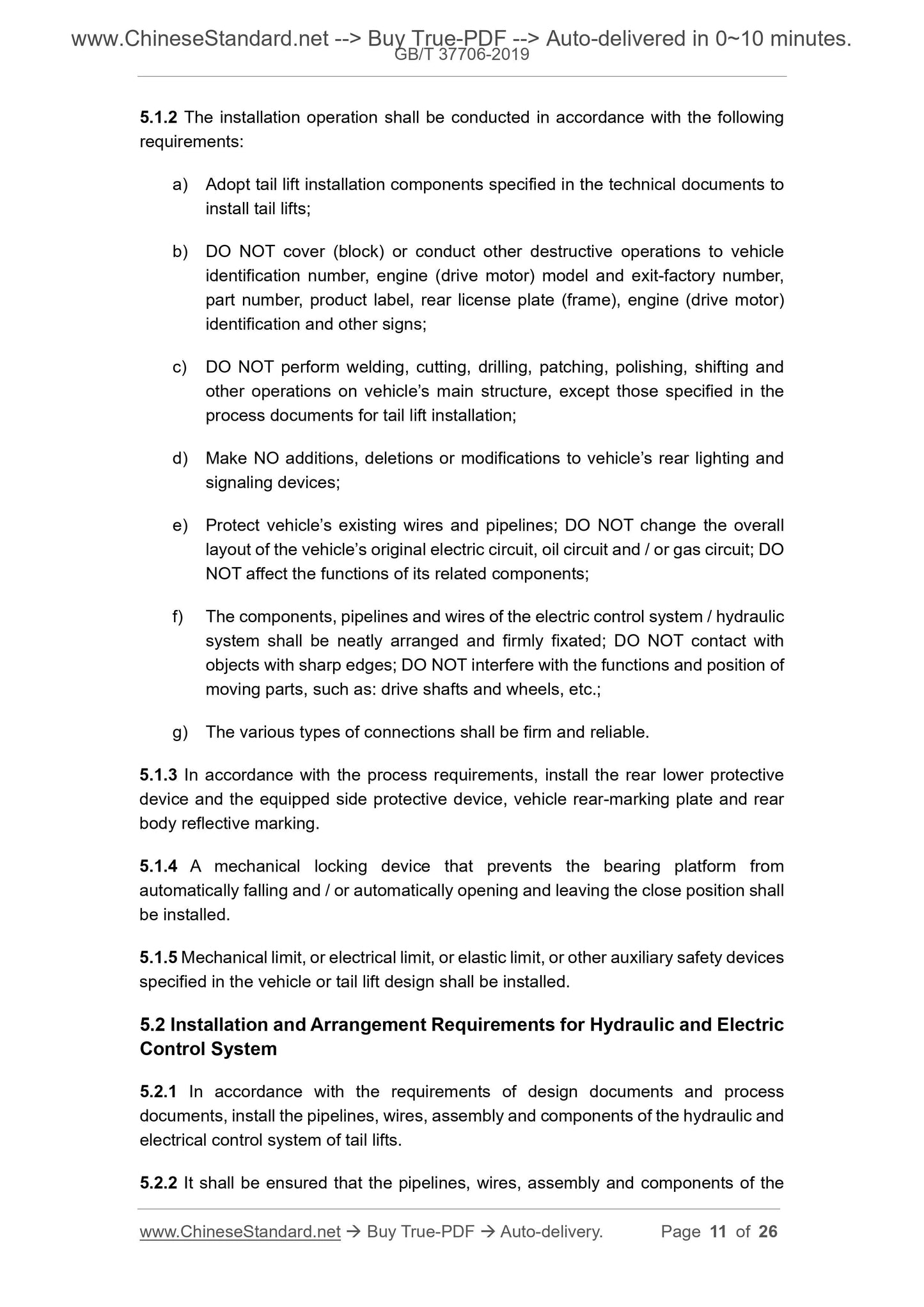
5.1.2 The installation operation shall be conducted in accordance with the following
requirements:
a) Adopt tail lift installation components specified in the technical documents to
install tail lifts;
b) DO NOT cover (block) or conduct other destructive operations to vehicle
identification number, engine (drive motor) model and exit-factory number,
part number, product label, rear license plate (frame), engine (drive motor)
identification and other signs;
c) DO NOT perform welding, cutting, drilling, patching, polishing, shifting and
other operations on vehicle’s main structure, except those specified in the
process documents for tail lift installation;
d) Make NO additions, deletions or modifications to vehicle’s rear lighting and
signaling devices;
e) Protect vehicle’s existing wires and pipelines; DO NOT change the overall
layout of the vehicle’s original electric circuit, oil circuit and / or gas circuit; DO
NOT affect the functions of its related components;
f) The components, pipelines and wires of the electric control system / hydraulic
system shall be neatly arranged and firmly fixated; DO NOT contact with
objects with sharp edges; DO NOT interfere with the functions and position of
moving parts, such as: drive shafts and wheels, etc.;
g) The various types of connections shall be firm and reliable.
5.1.3 In accordance with the process requirements, install the rear lower protective
device and the equipped side protective device, vehicle rear-marking plate and rear
body reflective marking.
5.1.4 A mechanical locking device that prevents the bearing platform from
automatically falling and / or automatically opening and leaving the close position shall
be installed.
5.1.5 Mechanical limit, or electrical limit, or elastic limit, or other auxiliary safety devices
specified in the vehicle or tail lift design shall be installed.
5.2 Installation and Arrangement Requirements for Hydraulic and Electric
Control System
5.2.1 In accordance with the requirements of design documents and process
documents, install the pipelines, wires, assembly and components of the hydraulic and
electrical control system of tail lifts.
5.2.2 It shall be ensured that the pipelines, wires, assembly and components of the
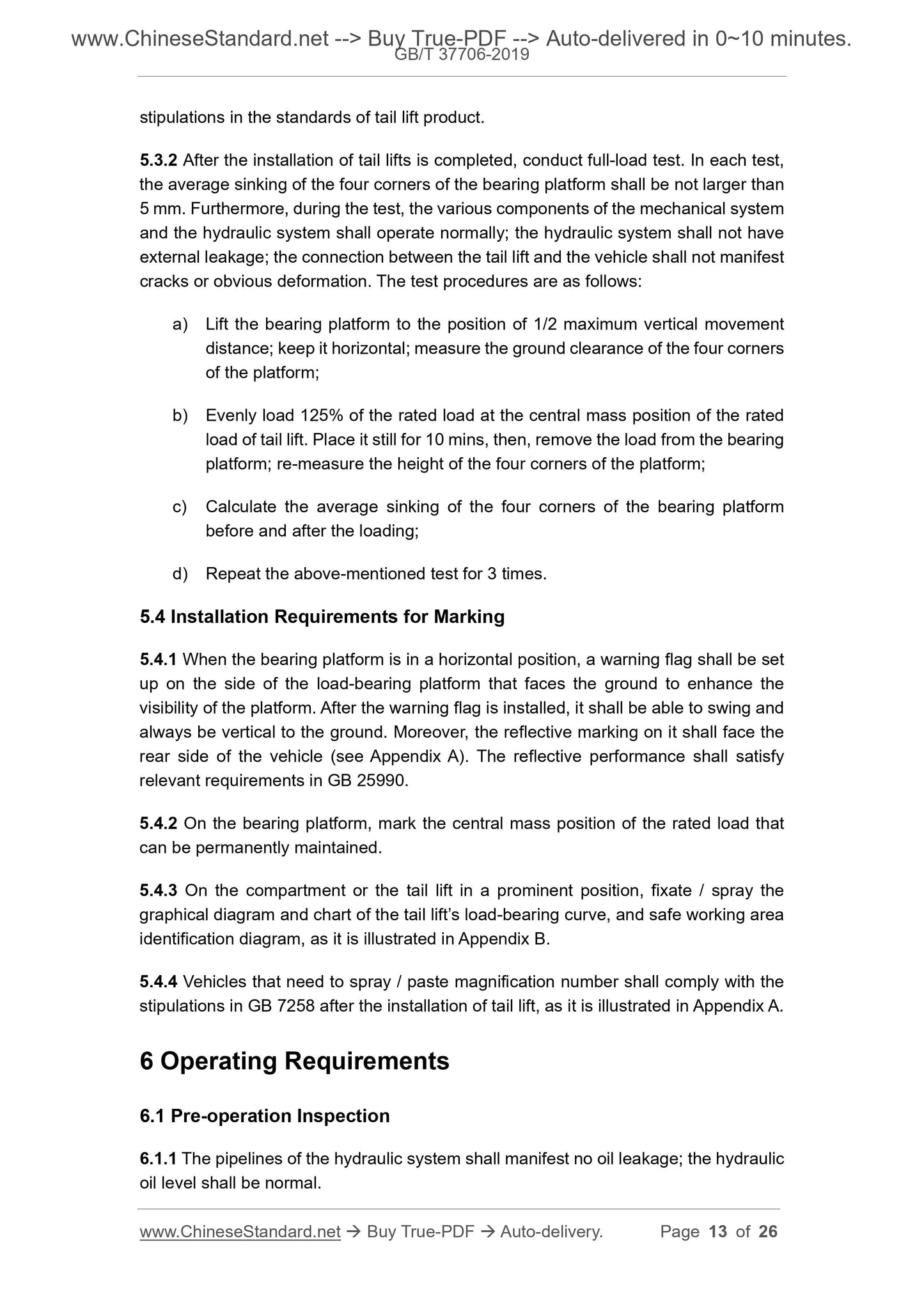
stipulations in the standards of tail lift product.
5.3.2 After the installation of tail lifts is completed, conduct full-load test. In each test,
the average sinking of the four corners of the bearing platform shall be not larger than
5 mm. Furthermore, during the test, the various components of the mechanical system
and the hydraulic system shall operate normally; the hydraulic system shall not have
external leakage; the connection between the tail lift and the vehicle shall not manifest
cracks or obvious deformation. The test procedures are as follows:
a) Lift the bearing platform to the position of 1/2 maximum vertical movement
distance; keep it horizontal; measure the ground clearance of the four corners
of the platform;
b) Evenly load 125% of the rated load at the central mass position of the rated
load of tail lift. Place it still for 10 mins, then, remove the load from the bearing
platform; re-measure the height of the four corners of the platform;
c) Calculate the average sinking of the four corners of the bearing platform
before and after the loading;
d) Repeat the above-mentioned test for 3 times.
5.4 Installation Requirements for Marking
5.4.1 When the bearing platform is in a horizontal position, a warning flag shall be set
up on the side of the load-bearing platform that faces the ground to enhance the
visibility of the platform. After the warning flag is installed, it shall be able to swing and
always be vertical to the ground. Moreover, the reflective marking on it shall face the
rear side of the vehicle (see Appendix A). The reflective performance shall satisfy
relevant requirements in GB 25990.
5.4.2 On the bearing platform, mark the central mass position of the rated load that
can be permanently maintained.
5.4.3 On the compartment or the tail lift in a prominent position, fixate / spray the
graphical diagram and chart of the tail lift’s load-bearing curve, and safe working area
identification diagram, as it is illustrated in Appendix B.
5.4.4 Vehicles that need to spray / paste magnification number shall comply with the
stipulations in GB 7258 after the installation of tail lift, as it is illustrated in Appendix A.
6 Operating Requirements
6.1 Pre-operation Inspection
6.1.1 The pipelines of the hydraulic system shall manifest no oil leakage; the hydraulic
oil level shall be normal.
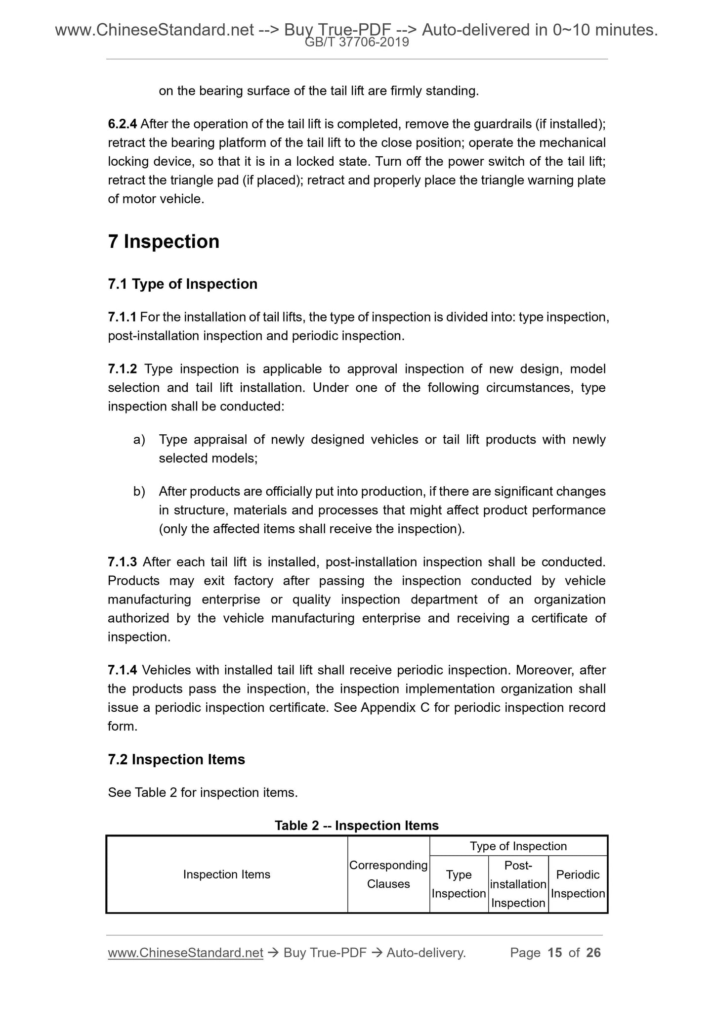
on the bearing surface of the tail lift are firmly standing.
6.2.4 After the operation of the tail lift is completed, remove the guardrails (if installed);
retract the bearing platform of the tail lift to the close position; operate the mechanical
locking device, so that it is in a locked state. Turn off the power switch of the tail lift;
retract the triangle pad (if placed); retract and properly place the triangle warning plate
of motor vehicle.
7 Inspection
7.1 Type of Inspection
7.1.1 For the installation of tail lifts, the type of inspection is divided into: type inspection,
post-installation inspection and periodic inspection.
7.1.2 Type inspection is applicable to approval inspection of new design, model
selection and tail lift installation. Under one of the following circumstances, type
inspection shall be conducted:
a) Type appraisal of newly designed vehicles or tail lift products with newly
selected models;
b) After products are officially put into production, if there are significant changes
in structure, materials and processes that might affect product performance
(only the affected items shall receive the inspection).
7.1.3 After each tail lift is installed, post-installation inspection shall be conducted.
Products may exit factory after passing the inspection conducted by vehicle
manufacturing enterprise or quality inspection department of an organization
authorized by the vehicle manufacturing enterprise and receiving a certificate of
inspection.
7.1.4 Vehicles with installed tail lift shall receive periodic inspection. Moreover, after
the products pass the inspection, the inspection implementation organization shall
issue a periodic inspection certificate. See Appendix C for periodic inspection record
form.
7.2 Inspection Items
See Table 2 for inspection items.
Table 2 -- Inspection Items
Inspection Items Corresponding Clauses
Type of Inspection
Type
Inspection
Post-
installation
Inspection
Periodic
Inspection
GB/T 37706-2019
NATIONAL STANDARD OF THE
PEOPLE’S REPUBLIC OF CHINA
ICS 53.020.20
R 14
Installation and Operation Technical Requirements of
Tail Lifts for Vehicle
ISSUED ON: MAY 10, 2019
IMPLEMENTED ON: DECEMBER 1, 2019
Issued by: State Administration for Market Regulation;
Standardization Administration of the People’s Republic of
China.
Table of Contents
Foreword ... 3 
1 Scope ... 4 
2 Normative References ... 4 
3 Terms and Definitions ... 5 
View full details