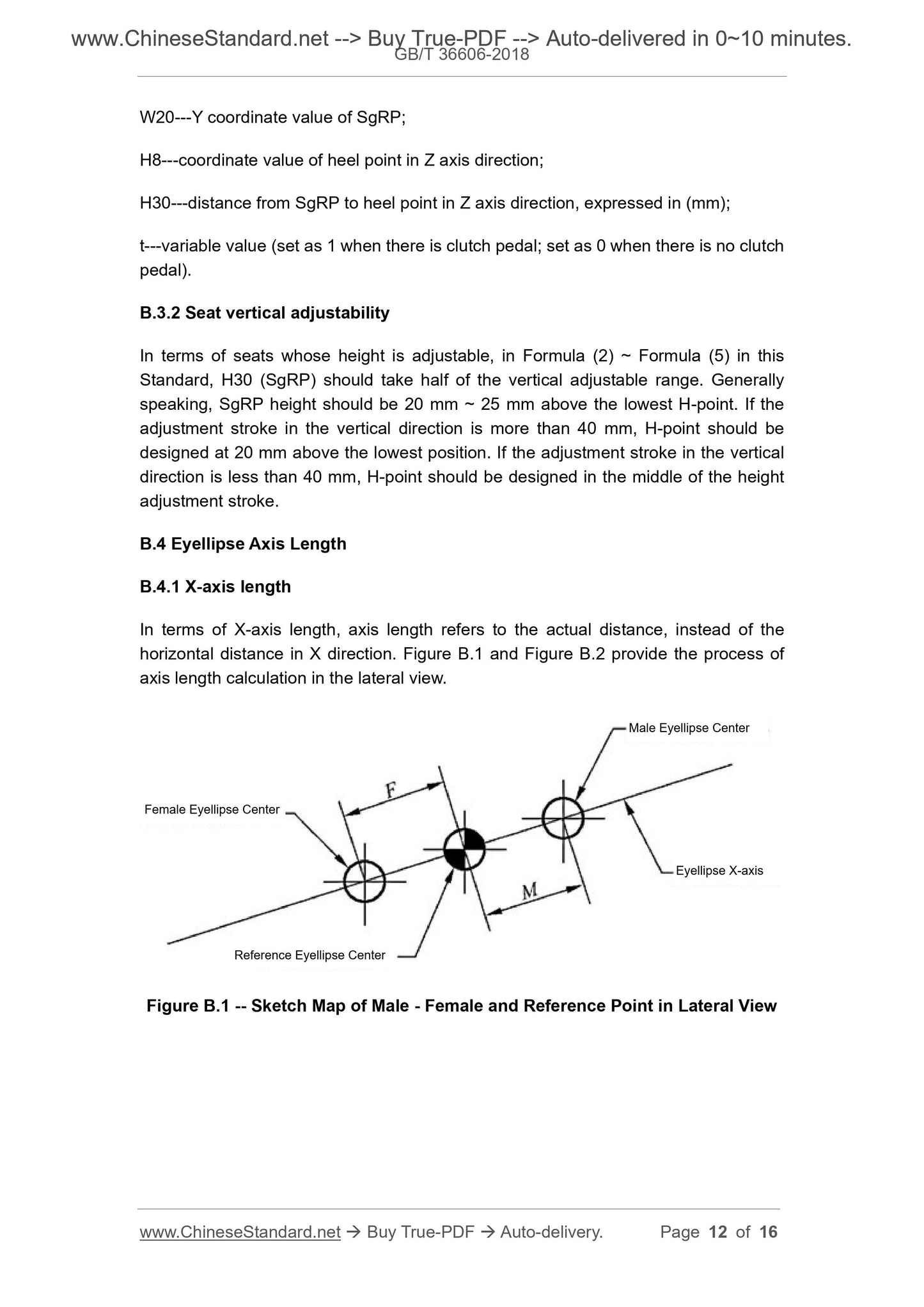
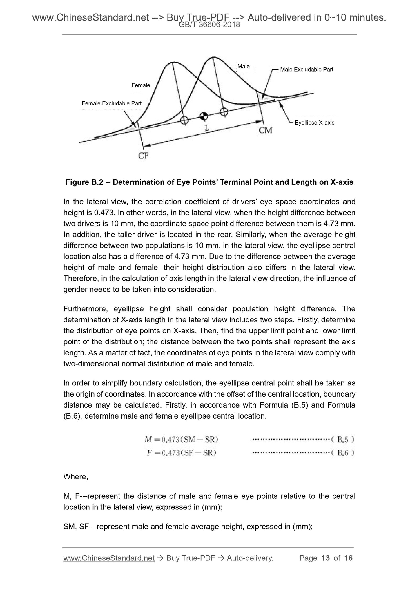
This Standard provides eye locations and eyellipse positioning procedure for Chinese motor vehicle drivers. This Standard is applicable to visual field design for Class M1 motor vehicles whose seat stroke is more than 133 mm.
Basic Data
Standard ID
GB/T 36606-2018 (GB/T36606-2018)
Description (Translated English)
Ergonomics - Motor Vehicle Drivers Eye Locations
Sector / Industry
National Standard (Recommended)
Classification of Chinese Standard
A25
Classification of International Standard
13.180
Word Count Estimation
14,124
Date of Issue
2018-09-17
Date of Implementation
2019-01-01
Issuing agency(ies)
State Administration for Market Regulation, China National Standardization Administration