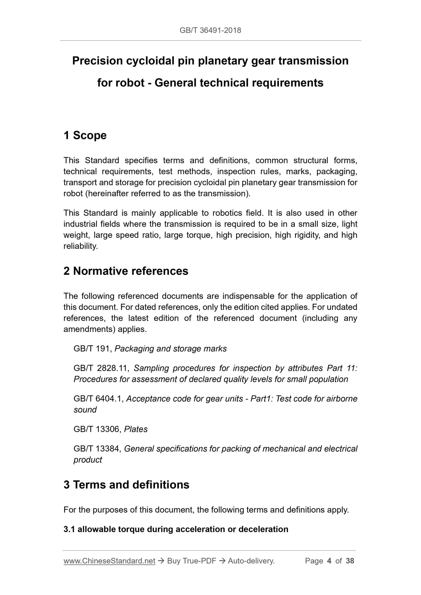
This Standard specifies terms and definitions, common structural forms, technical requirements, test methods, inspection rules, marks, packaging, transport and storage for precision cycloidal pin planetary gear transmission for robot (hereinafter referred to as the transmission). This Standard is mainly applicable to robotics field. It is also used in other industrial fields where the transmission is required to be in a small size, light weight, large speed ratio, large torque, high precision, high rigidity, and high reliability.
Basic Data
Standard ID
GB/T 36491-2018 (GB/T36491-2018)
Description (Translated English)
Precision cycloidal pin planetary gear transmission for robot - General technical requirements
Sector / Industry
National Standard (Recommended)
Classification of Chinese Standard
J17
Classification of International Standard
21.200
Word Count Estimation
30,338
Date of Issue
2018-07-13
Date of Implementation
2019-02-01
Issuing agency(ies)
State Administration for Market Regulation, China National Standardization Administration