GB/T 36405-2018 English PDF (GBT36405-2018)
Regular price
$175.00 USD
Regular price
Sale price
$175.00 USD
Unit price
/
per
Delivery: 3 seconds. Download true-PDF + Invoice.
Get QUOTATION in 1-minute: Click GB/T 36405-2018
Historical versions: GB/T 36405-2018
Preview True-PDF (Reload/Scroll if blank)
GB/T 36405-2018: Test method for stress in flat glass
GB/T 36405-2018
GB
NATIONAL STANDARD OF THE
PEOPLE’S REPUBLIC OF CHINA
Test Method for Stress in Flat Glass
ISSUED ON. JUNE 7, 2018
IMPLEMENTED ON. MAY 1, 2019
Issued by. State Administration for Market Regulation of the People’s
Republic of China;
Standardization Administration Committee of the People’s
Republic of China.
Table of Contents
Foreword ... 3
1 Scope ... 4
2 Normative References ... 4
3 Terms and Definitions ... 4
4 Test Principle ... 5
5 Stress Test Method ... 7
6 Test Report ... 15
Foreword
This Standard is drafted in accordance with stipulations in GB/T 1.1-2009.
This Standard is proposed by China Building Materials Federation.
This Standard is summarized by National Technical Committee 255 on Architectural
Glass of Standardization Administration of China (SAC/TC 255).
This Standard is drafted by China Building Material Test and Certification Group
Qinhuangdao Co., Ltd. (National Glass Quality Supervision and Inspection Center),
China Construction Fourth Engineering Division Co., Ltd., TAIWANGLASS CFG,
Center Testing International Group Co., Ltd., Beijing Aoptek Scientific Co., Ltd., Flat
Glass Group, Fuyao Glass, Foshan Shunde District Quality and Technology
Supervision Standard and Coding Office, Hubei Provincial Academy of Building
Research and Design, Sichuan Henggu Construction Project Examination Co., Ltd.,
Dongguan HUAXI Mechanical and Electrical Engineering Co., Ltd., Hebei RUN’AN
Building Material Co., Ltd., Beijing Xin Yuan Bo Heng Detection Science and
Technology Co., Ltd., Hebei Macros Star Detection Co., Ltd.
The main drafters of this Standard include. Ji Shuwei, Zhang Zhemin, Wuxiao, Huang
Jianbin, Li Xingang, Liyao, Lihu, Yangwei, Xujiang, Ruan Hongliang, Gaofeng, He
Shimeng, Li Junsheng, Zhouqun, Shen Minqi, Wen Hanping, Sang Luming, Meng
Caiqing, Ligen.
Test Method for Stress in Flat Glass
1 Scope
This Standard specifies terms, definition, test principle, stress test method and test
report related with flat glass stress test.
This Standard is applicable to the test of annealed flat glass plane stress and plate
thickness stress.
2 Normative References
The following documents are indispensable to the application of this Standard. In terms
of references with a specified date, only versions with a specified date are applicable
to this Standard. The latest version (including all the modifications) of references
without a specified date is also applicable to this Standard.
GB/T 15764 Standard Definitions of Terms Relating to Flat Glass
3 Terms and Definitions
The following terms and definitions, as well as terms and definitions provided in GB/T
15764 are applicable to this Standard.
3.1 Plane Stress
Plane stress is permanent tensile stress or compressive stress that exists among
different areas of plane glass after the glass is molded.
3.2 Interior Stress
It is permanent stress generated by temperature gradient under the plate thickness
direction after the glass is molded. Compressive stress exists on the surface, and
tensile stress exists in the central area.
3.3 Polarizer
Polarizer is placed between light source and the sample being tested. It turns natural
light into a device with plane polarized light and a certain vibration direction.
3.4 Analyzer
Analyzer is placed between the sample being tested and the observer. It is a polarizing
device adopted to analyze polarization.
Randomly draw a piece of finished product, and cut 600 mm x 600 mm of sample along
the same direction or the direction of the board width.
5.1.3.2 Sample processing
Rinse the sample, guarantee that the surface is clean and there’s no attachment.
5.1.4 Determination of test area
The central section (diameter. 500 mm) of the sample is test area.
5.1.5 Test steps
Please see the test steps below.
a) Measure the thickness of the sample (accurate to 0.1 mm);
b) Activate stress detector; make the main direction of the polarizer and analyzer
mutually orthogonal;
c) Place the test sample between the polarizer and analyzer, then, make the surface
of the sample vertical to the optical path; horizontally place the samples in
accordance with the pulling direction;
d) Operate the stress detector through the test and control software in accordance
with the instrument specification, then, complete the stress test and calculation
of the test area;
e) Record stress distribution diagram and the measured stress value of various
points in the test area in accordance with the sample number.
5.1.6 Expression of test result
5.1.6.1 Plate stress distribution diagram
Calculate the stress value of the test area of the test sample in accordance with
Formula (6). Calculate the absolute value of the stress value on the plane of x y
coordinate; draw the plane stress distribution of the test sample with grayscale or
colors.
5.1.6.2 Average value of plate stress
Calculate the positive value of tensile stress and compressive stress; calculate the
arithmetic mean value of stress within the test area.
5.1.6.3 Maximum value of plate stress
The maximum value of the absolute value of stress within the test area.
Where.
I (x, y) - Light intensity distribution detected by camera;
Io - Same as Formula (7);
T - Same as Formula (7);
ẟ (x, y) - Stress birefringence phase difference of the test point, expressed in (rad).
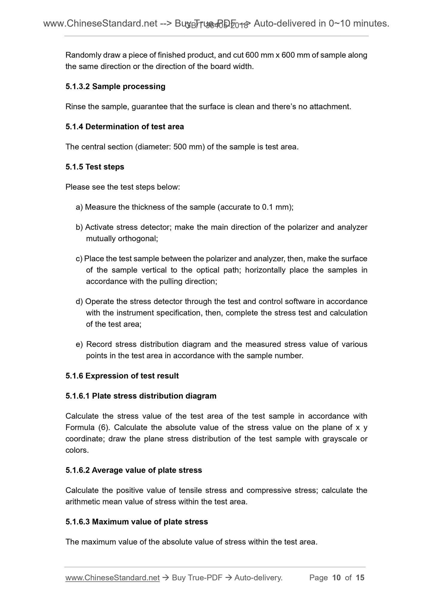
Stress birefringence phase difference of the test point shall be calculated in
accordance with Formula (9).
5.2.4 Stress calculation
Birefringence optical path difference △ (x, y) shall be calculated in accordance with
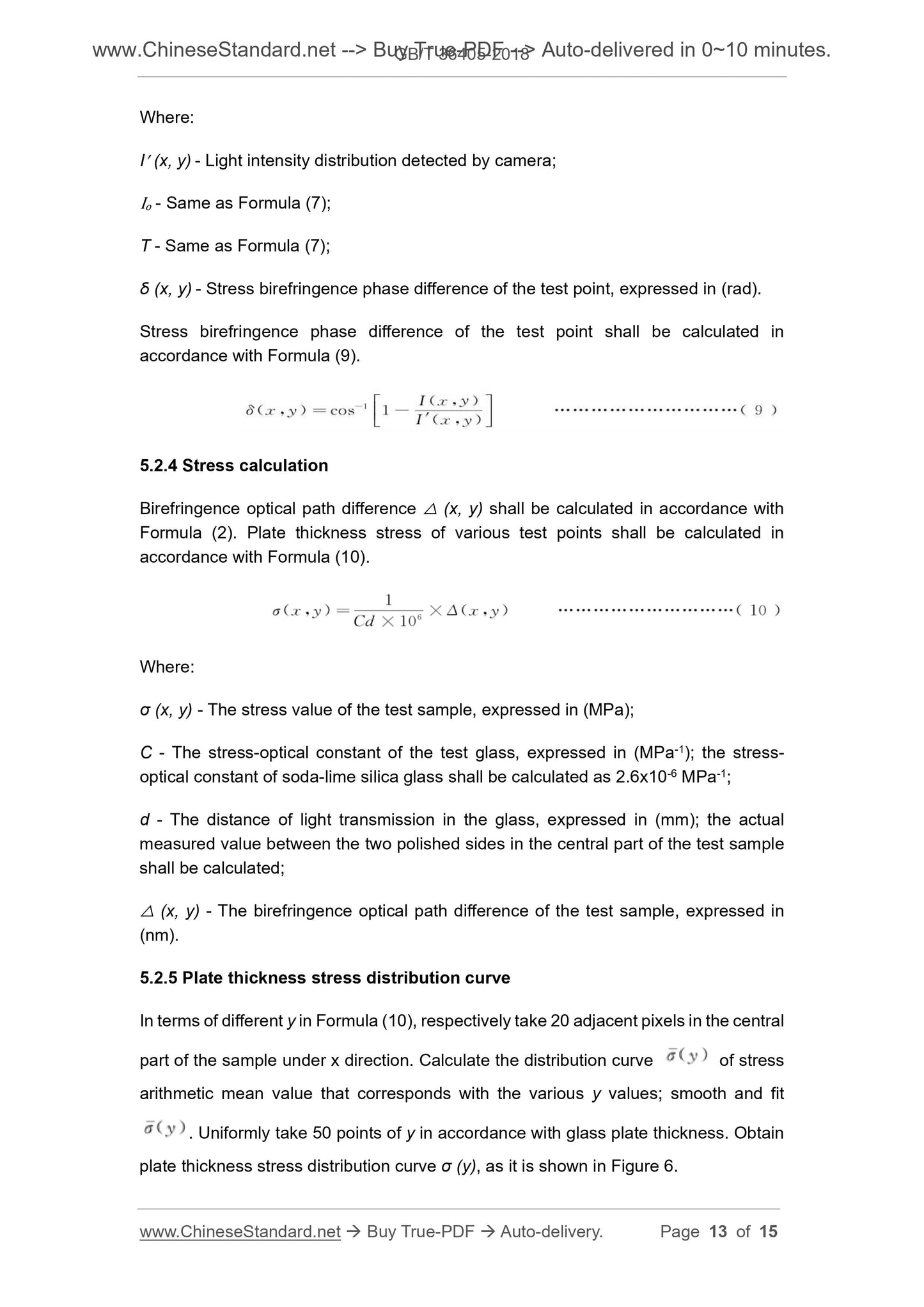
Formula (2). Plate thickness stress of various test points shall be calculated in
accordance with Formula (10).
Where.
σ (x, y) - The stress value of the test sample, expressed in (MPa);
C - The stress-optical constant of the test glass, expressed in (MPa-1); the stress-
optical constant of soda-lime silica glass shall be calculated as 2.6x10⁻⁶ MPa-1;
d - The distance of light transmission in the glass, expressed in (mm); the actual
measured value between the two polished sides in the central part of the test sample
shall be calculated;
△ (x, y) - The birefringence optical path difference of the test sample, expressed in
(nm).
5.2.5 Plate thickness stress distribution curve
In terms of different y in Formula (10), respectively take 20 adjacent pixels in the central
part of the sample under x direction. Calculate the distribution curve of stress
arithmetic mean value that corresponds with the various y values; smooth and fit
. Uniformly take 50 points of y in accordance with glass plate thickness. Obtain
plate thickness stress distribution curve σ (y), as it is shown in Figure 6.