PayPal, credit cards. Download editable-PDF & invoice In 1 second!
GB/T 36126-2018 English PDF (GBT36126-2018)
Couldn't load pickup availability
GB/T 36126-2018: Liquefied natural gas dispenser for vehicle
GB
NATIONAL STANDARD OF THE
PEOPLE’S REPUBLIC OF CHINA
ICS 17.120
A 53
Liquefied natural gas dispenser for vehicle
ISSUED ON. MAY 14, 2018
IMPLEMENTED ON. DECEMBER 1, 2018
Issued by. State Administration for Market Regulation;
Standardization Administration of the PRC.
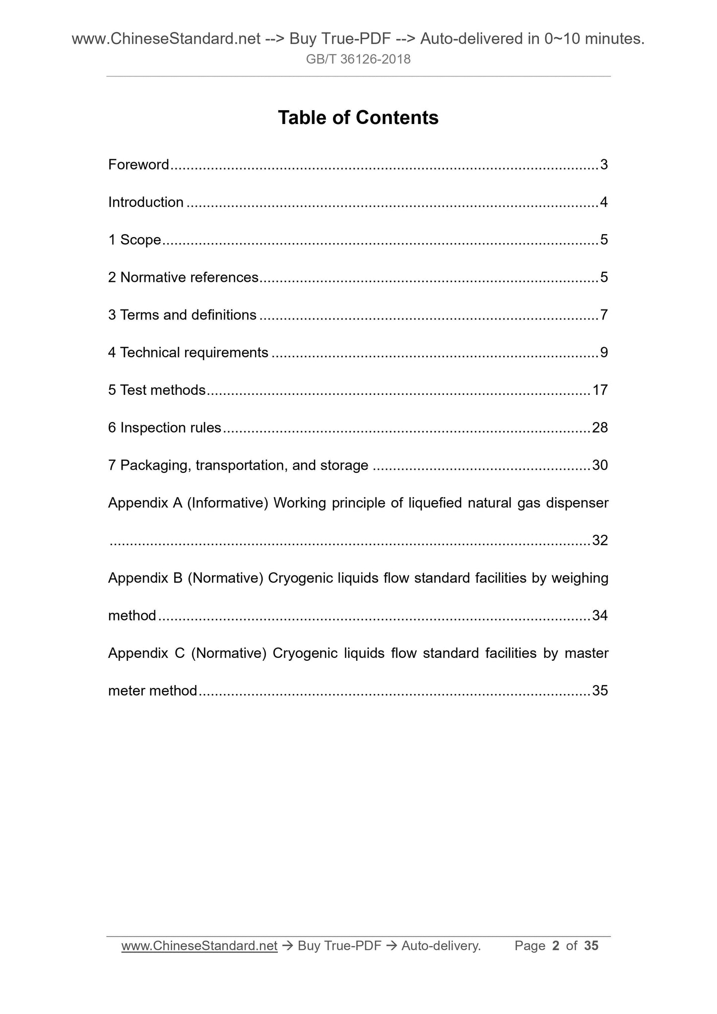
Table of Contents
Foreword ... 3
Introduction ... 4
1 Scope ... 5
2 Normative references ... 5
3 Terms and definitions ... 7
4 Technical requirements ... 9
5 Test methods ... 17
6 Inspection rules ... 28
7 Packaging, transportation, and storage ... 30
Appendix A (Informative) Working principle of liquefied natural gas dispenser ... 32
Appendix B (Normative) Cryogenic liquids flow standard facilities by weighing method ... 34
Appendix C (Normative) Cryogenic liquids flow standard facilities by master meter method ... 35
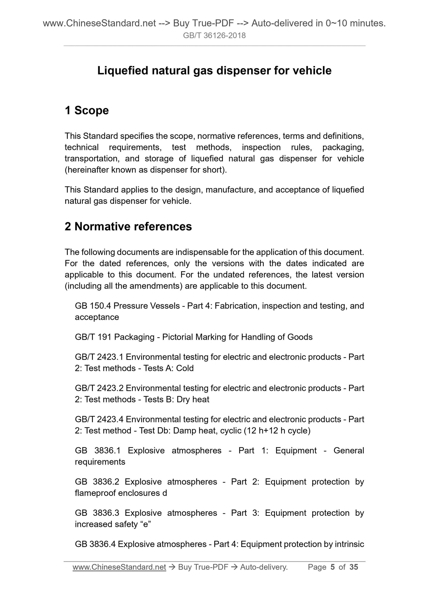
Liquefied natural gas dispenser for vehicle
1 Scope
This Standard specifies the scope, normative references, terms and definitions, technical requirements, test methods, inspection rules, packaging,
transportation, and storage of liquefied natural gas dispenser for vehicle (hereinafter known as dispenser for short).
This Standard applies to the design, manufacture, and acceptance of liquefied natural gas dispenser for vehicle.
2 Normative references
The following documents are indispensable for the application of this document. For the dated references, only the versions with the dates indicated are applicable to this document. For the undated references, the latest version (including all the amendments) are applicable to this document.
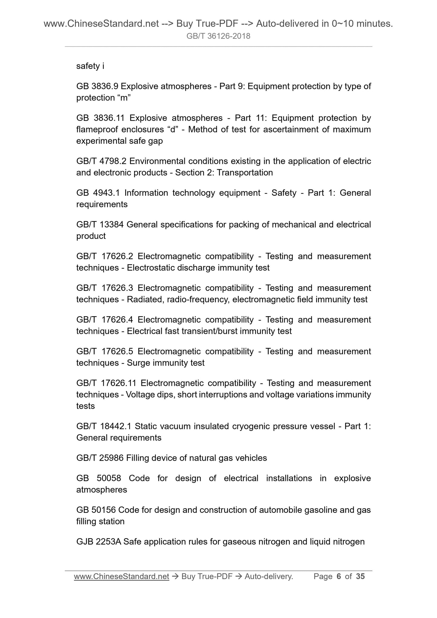
GB 150.4 Pressure Vessels - Part 4. Fabrication, inspection and testing, and acceptance
GB/T 191 Packaging - Pictorial Marking for Handling of Goods
GB/T 2423.1 Environmental testing for electric and electronic products - Part 2. Test methods - Tests A. Cold
GB/T 2423.2 Environmental testing for electric and electronic products - Part 2. Test methods - Tests B. Dry heat
GB/T 2423.4 Environmental testing for electric and electronic products - Part 2. Test method - Test Db. Damp heat, cyclic (12 h+12 h cycle)
GB 3836.1 Explosive atmospheres - Part 1. Equipment - General
requirements
GB 3836.2 Explosive atmospheres - Part 2. Equipment protection by
flameproof enclosures d
GB 3836.3 Explosive atmospheres - Part 3. Equipment protection by
increased safety “e”
GB 3836.4 Explosive atmospheres - Part 4. Equipment protection by intrinsic safety i
GB 3836.9 Explosive atmospheres - Part 9. Equipment protection by type of protection “m”
GB 3836.11 Explosive atmospheres - Part 11. Equipment protection by
flameproof enclosures “d” - Method of test for ascertainment of maximum experimental safe gap
GB/T 4798.2 Environmental conditions existing in the application of electric and electronic products - Section 2. Transportation
GB 4943.1 Information technology equipment - Safety - Part 1. General
requirements
GB/T 13384 General specifications for packing of mechanical and electrical product
GB/T 17626.2 Electromagnetic compatibility - Testing and measurement
techniques - Electrostatic discharge immunity test
GB/T 17626.3 Electromagnetic compatibility - Testing and measurement
techniques - Radiated, radio-frequency, electromagnetic field immunity test GB/T 17626.4 Electromagnetic compatibility - Testing and measurement
techniques - Electrical fast transient/burst immunity test
GB/T 17626.5 Electromagnetic compatibility - Testing and measurement
techniques - Surge immunity test
GB/T 17626.11 Electromagnetic compatibility - Testing and measurement
techniques - Voltage dips, short interruptions and voltage variations immunity tests
GB/T 18442.1 Static vacuum insulated cryogenic pressure vessel - Part 1. General requirements
GB/T 25986 Filling device of natural gas vehicles
GB 50058 Code for design of electrical installations in explosive
atmospheres
GB 50156 Code for design and construction of automobile gasoline and gas filling station
GJB 2253A Safe application rules for gaseous nitrogen and liquid nitrogen cryogenic liquefied gas (such as liquid nitrogen or LNG), as a test medium, through a master flowmeter and a flowmeter under test at the same interval. The facilities generally consist of a fluid source, a test piping system, a master flowmeter, a flow regulating valve, and ancillary equipment, etc..
4 Technical requirements
4.1 General
The dispenser shall generally meet.
a) All equipment and piping components in the dispenser which are in contact with LNG shall be of a material that conforms to the LNG cryogenic piping design code.
b) The design pressure of all equipment and piping components in the
dispenser shall comply with the relevant requirements of GB 50156.
4.2 Basic functions
4.2.1 Metering and pricing functions
The metering and pricing functions of dispenser shall meet.
a) The dispenser shall have a metering function. The fueling amount of
dispenser is measured by mass. The unit of mass is kilograms (kg). The
unit of flow is kilograms per minute (kg/min).
b) The dispenser shall have a pricing function. The unit of payment amount is yuan. The unit of unit price is yuan per kilogram (yuan/kg).
4.2.2 Value indication function
The value indication function of dispenser shall meet.
a) The dispenser shall have a value indication function. The indication reading shall be correct, easy to read, and clear.
b) The minimum quality variable of dispenser is expressed as 1×10n, 2×10n, or 5 ×10n, where n is a positive integer, a negative integer, or zero.
c) When there are more than 2 display indication values, the display of each indication value shall be consistent. The indication value shall be
continuously displayed during the fueling process.
4.2.3 Zero return function
be changed at will.
4.2.8 Anti-overfill function
In order to prevent the vessel from being overfilled, during the fueling process, the fueling and reclaiming functions of dispenser shall be avoided operating simultaneously.
4.2.9 Auxiliary functions
The auxiliary functions of dispenser include. IC card information reading-writing, data management, and network extension, etc..
4.3 Marking and identification
The marking and identification of dispenser shall meet.
a) The marking and identification of dispenser shall be clear and
distinguishable, solid and reliable.
b) There shall be obvious safety and operation identifications on the
dispenser.
c) For dispensers with two fueling nozzles and above, the fueling nozzle shall have a corresponding mark.
d) The nameplate of dispenser generally indicates the following.
manufacturer’s name (trademark), product name and model specification,
date of manufacture, exit-factory number, marking and number of license for manufacture of measuring instrument (Note. The new product
applicant organization shall reserve a place for the corresponding content on prototype nameplate design), applicable medium, flow range, accuracy level or maximum allowable error, applicable ambient temperature range, maximum working pressure, supply voltage, explosion-proof sign, and
explosion-proof conformity certificate number, etc..
4.4 Appearance and structure
The appearance and structure of dispenser shall meet.
a) There shall be no peeling, falling off, rust, etc. on the surface of dispenser. b) The nameplate and marking of dispenser shall be clear, complete, and accurate.
c) The fasteners of dispenser shall be firmly connected without looseness. The connectors shall be in good contact. The connecting wires shall be
the on-off operation of corresponding valve.
c) The emergency shutdown device shall be located in the obvious position of dispenser. Its function shall be identified. There shall be protective measures preventing malfunction.
d) After the emergency shutdown device is triggered, it shall be manually confirmed before resetting.
4.9 Breakaway protection device
The breakaway protection device of dispenser shall meet.
a) The fueling hose of dispenser shall be equipped with a breakaway
protection device, which shall be disconnected into two sections under the rated breakaway force (600 N~900 N).
b) The reclaiming hose of dispenser shall be equipped with a breakaway
protection device, which shall be disconnected into two sections under the rated breakaway force (400 N~600 N).
c) The breakaway protection device for larger breakaway force used in
special occasions shall be marked with its rated breakaway force on the surface and in the specification.
4.10 Safety protection device
The safety protection device of dispenser shall meet.
a) The dispenser shall be equipped with safety protection devices such as safety valves.
b) Safety protection devices such as safety valves shall obtain the test certificate or identification issued by the safety valve testing agency with corresponding qualifications.
4.11 Power-down protection and re-display functions
The power-down protection and re-display functions of dispenser shall meet. a) When the dispenser, during the fueling process, interrupts fueling due to power failure, it shall be able to retain all data intact.
b) When the fault occurs, the display time for the current fueling amount and payment amount shall not be less than 30 min. Or within 1 h after the fault occurs, the sum of the time of manual control of single or multiple re- displays shall not be less than 20 min.
4.13.5 Payment amount error
The payment amount displayed on dispenser panel shall not be greater than the calculated payment amount (the product of the unit price and the fueling amount indication value displayed on the panel).
4.14 Environmental adaptability
4.14.1 Low temperature adaptability
The dispenser shall, at a low temperature of -25 °C, be able to work normally. During the test and after the test, within the specified limits, the performance of dispenser is normal. The data shall not be lost. The program or content stored in the memory cannot be changed in any way. The state cannot be changed. The level of each point on all interfaces cannot be abnormally changed. 4.14.2 High temperature adaptability
The dispenser shall, at a high temperature of 55 °C, be able to work normally. During the test and after the test, within the specified limits, the performance of dispenser is normal. The data shall not be lost. The program or content stored in the memory cannot be changed in any way. The state cannot be changed. The level of each point on all interfaces cannot be abnormally changed. 4.14.3 Cyclic damp heat adaptability
The dispenser shall, in a cyclic damp heat environment with a temperature of 25 °C~55 °C and a relative humidity of 93%~95%, be able to work normally. During the test and after the test, within the specified limits, the performance of dispenser is normal. The data shall not be lost. The program or content stored in the memory cannot be changed in any way. The state cannot be changed. The level of each point on all interfaces cannot be abnormally changed. 4.14.4 Power adaptability
The dispenser shall, in the power supply environment with a voltage of
85%~110% of the nominal voltage of the power supply and a supply frequency of (50±1) Hz, be able to work normally. During the test and after the test, within the specified limits, the performance of dispenser is normal. The data shall not be lost. The program or content stored in the memory cannot be changed in any way. The state cannot be changed. The level of each point on all interfaces cannot be abnormally changed.
4.14.5 Electrostatic discharge immunity
The dispenser shall, under the contact discharge of 8 kV test voltage and the After the environmental adaptability test, according to the requirements of 4.13, the metering performance of dispenser shall be retested.
4.16 Durability
After the durability test, the maximum allowable error and repeatability of dispenser shall comply with the requirements of 4.13.1 and 4.13.2. The
variation of indication error, compared with that before the test, shall not exceed 0.5%.
4.17 Transportation adaptability
Under the conditions of packaging and transportation, the dispenser, after the transportation adaptability test, shall meet the requirements of 4.2 and 4.13. 4.18 Key components
4.18.1 Cryogenic flowmeter
The cryogenic flowmeter shall meet.
a) The cryogenic flowmeter used in dispenser shall have a clear nameplate and complete identification. The metering accuracy level shall not be lower than level 0.5.
b) The flow range, temperature range, pressure range, and medium used of cryogenic flowmeter shall meet the technical requirements of dispenser. c) The cryogenic flowmeter shall obtain the license for manufacture of
measuring instrument and explosion-proof conformity certificate.
d) The dispenser for trade settlement shall be equipped with a liquid phase flowmeter for measuring the fueling amount and a gas phase flowmeter
for measuring the reclaiming amount.
4.18.2 Electronic computer
The electronic computer shall have an indication function, a zero return function, an error adjustment function, and a payment amount indication function, etc.. 5 Test methods
5.1 Basic functions
According to the requirements of 4.2, the basic functions of dispenser are checked by visual and conventional methods.
According to the requirements of 4.11, PERFORM the test of power-down
protection and re-display functions. TURN on the dispenser for fueling; during the fueling process, DISCONNECT the power supply; and RECORD the display time for the fueling amount and payment amount. If the dispenser cannot display the fueling amount or the payment amount, RECORD the sum of the time of manual control of single or multiple re-displays within 1 h after the power failure.
5.11 Electrical safety performance
Electrical safety performance tests shall be carried out in accordance with the following requirements.
a) According to the requirements of 4.12, by the method of GB 4943.1, the earth leakage current of dispenser is tested.
b) According to the requirements of 4.12, by the method of GB 4943.1, the dielectric strength of dispenser is tested.
c) According to the requirements of 4.12, by the method of GB 4943.1, the connecting resistance between the grounding terminal or grounding
contact of dispenser and the component to be grounded is tested.
d) According to the requirements of 4.12, by the method of GB 4943.1, the corrosion resistance of grounding terminal of dispenser and the
conductive components in contact with the connection end is tested.
5.12 Metering performance
5.12.1 Test medium
The metering performance test, according to the provisions of GJB 2253A, uses liquid nitrogen as the test medium.
5.12.2 Test equipment
The metering performance test uses cryogenic liquids flow standard facilities by weighing method (SEE Appendix B), also can use cryogenic liquids flow standard facilities by master meter method (verification facilities for LNG dispenser, hereinafter known as verification facilities for short, SEE Appendix C).
5.12.3 Test methods
5.12.3.1 Test flow point and number of tests
The test flow points are selected as shown in Table 1. The dispenser shall be Where.
Ej - The jth payment amount error of dispenser, in yuan.
Pj - The payment amount displayed on the dispenser panel after the jth
fueling, in yuan.
Qj - The fueling amount displayed on the dispenser panel after the jth
fueling, in kilograms (kg).
P - The unit price displayed on the dispenser panel, in yuan per kilogram (yuan/kg).
c) REPEAT 3 times. The payment amount error shall meet the requirements of 4.13.5.
5.13 Environmental adaptability
5.13.1 Low temperature adaptability
According to the severity in temperature lower limit test of GB/T 2423.1. temperature -25 °C, continuous standing time 2 h, recovery time 2 h, the test is conducted. After the test, according to the requirements of 4.14.1, the dispenser is checked.
5.13.2 High temperature adaptability
According to the severity in temperature upper limit test of GB/T 2423.2. temperature 55 °C, continuous standing time 2 h, recovery time 2 h, the test is conducted. After the test, according to the requirements of 4.14.2, the dispenser is checked.
5.13.3 Cyclic damp heat adaptability
According to the severity in GB/T 2423.4. upper limit of temperature 55 °C, lower limit of temperature 25 °C, relative humidity 93%~95%, 24 h cycle, the test is carried out. After the test, according to the requirements of 4.14.3, the dispenser is checked.
5.13.4 Power adaptability
According to the combinations of Table 2, the power adaptability test is carried out. After the test, according to the requirements of 4.14.4, the dispenser is checked.
Appendix A
(Informative)
Working principle of liquefied natural gas dispenser
The working principle of dispenser is as shown in Figure A.1.
The dispenser, based on the working state, determines the flow direction of the LNG. When the dispenser is idle for a long time, the liquid phase piping and the liquid phase flowmeter have higher temperatures. Through the “large circulation” process, the precooling of the piping and the flowmeter shall be completed first. The operator inserts the fueling nozzle into the circulation receptacle of dispenser, clicks the “precooling” button; and the dispenser enters the “large circulation” process. At this time, the dispenser is not metered. When the temperature of the liquid phase flowmeter drops to a preset value, the large circulation automatically ends, and the dispenser becomes “idle”. When the dispenser frequently fuels and there is no need for “large circulation” precooling, the operator inserts the fueling nozzle into the filling receptacle of the vessel, clicks the “fueling” button; and the dispenser enters the “small circulation” process. At this time, the dispenser is not metered. When the dispenser parameters reach the preset values, the small circulation automatically ends, and the dispenser automatically switches to the “fueling” state. The electronic computer of dispenser automatically controls the fueling process, performs calculation based on the flow signal output by the flowmeter, and displays the calculation result on the display screen of dispenser. After the fueling is completed, the dispenser automatically switches to the “idle” state. Before fueling, according to the need, the reclaiming nozzle of dispenser can be inserted into the reclaiming receptacle of the vessel; so that the residual gas in the vessel, through the gas phase flowmeter, returns to the LNG storage tank, and the internal pressure of the vessel is lowered, to ensure that the LNG can be smoothly added.
Appendix B
(Normative)
Cryogenic liquids flow standard facilities by weighing method
B.1 Expanded uncertainty
The expanded uncertainty (coverage factor k=2) of the indication error
measurement result of cryogenic liquids flow standard facilities by weighing method shall not exceed 1/3 of the absolute value of the maximum allowable error of dispenser.
B.2 Standard facilities
The main standard is an electronic balance, which shall be equipped with a verification certificate within the validity ...
Share