www.ChineseStandard.us -- Field Test Asia Pte. Ltd.
Regular price
$150.00
Regular price
Sale price
$150.00
Unit price
/
per
Sale
Sold out
Couldn't load pickup availability
Refresh
GB/T 36017-2018: Non-destructive Testing Instruments - X-ray Fluorescence Analysis Tube Delivery: 9 seconds. Download (and Email) true-PDF + Invoice.
Get Quotation: Click
GB/T 36017-2018 (Self-service in 1-minute)
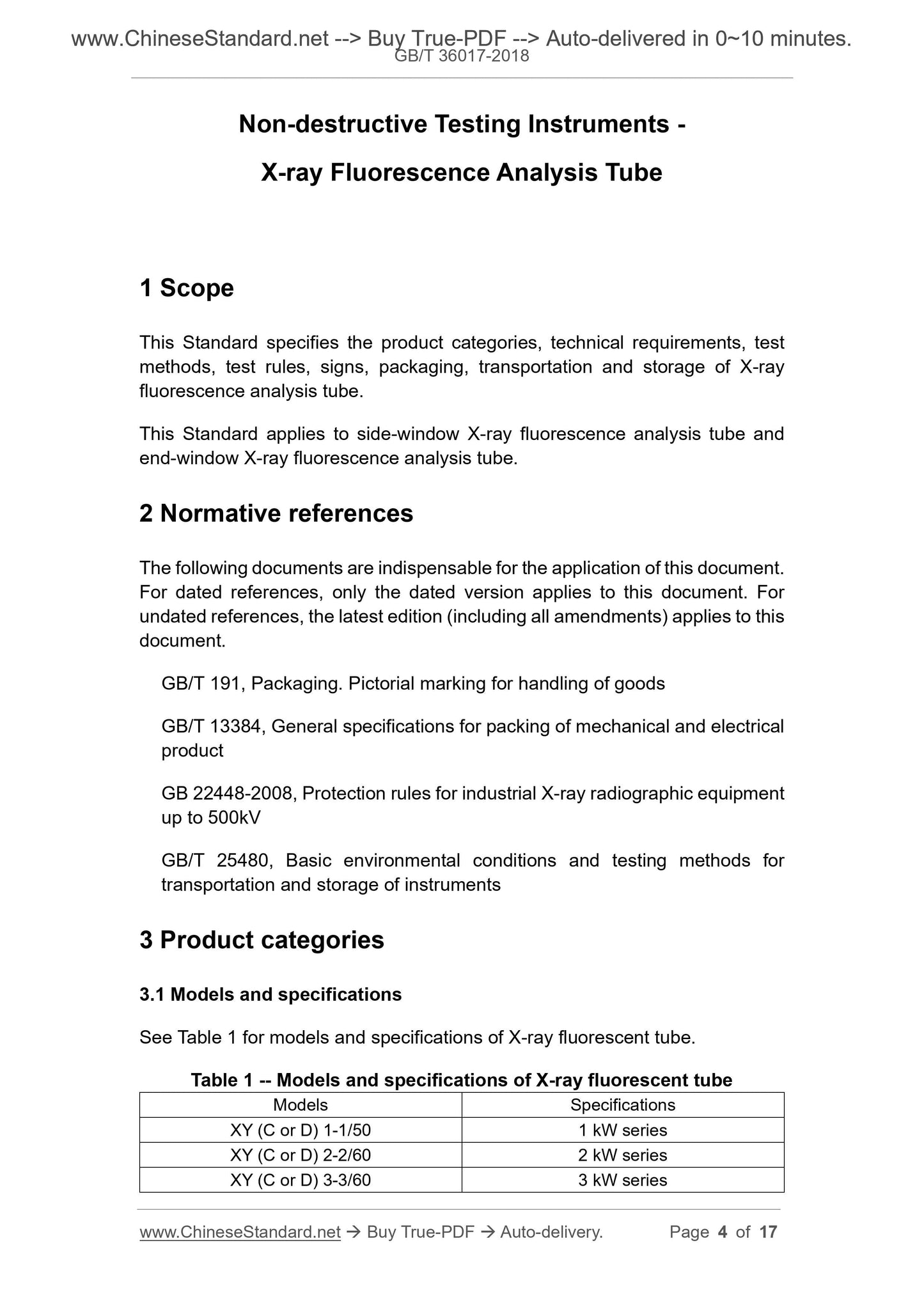
Newer / historical versions: GB/T 36017-2018 Preview True-PDF Scope This Standard specifies the product categories, technical requirements, test
methods, test rules, signs, packaging, transportation and storage of X-ray
fluorescence analysis tube.
This Standard applies to side-window X-ray fluorescence analysis tube and
end-window X-ray fluorescence analysis tube.
Basic Data Standard ID GB/T 36017-2018 (GB/T36017-2018)
Description (Translated English) Non-destructive Testing Instruments - X-ray Fluorescence Analysis Tube
Sector / Industry National Standard (Recommended)
Classification of Chinese Standard N78
Classification of International Standard 19.100
Word Count Estimation 14,128
Date of Issue 2018-03-15
Date of Implementation 2018-10-01
Issuing agency(ies) State Administration for Market Regulation, China National Standardization Administration
View full details