Skip to product information
1 of 8

www.ChineseStandard.us -- Field Test Asia Pte. Ltd.

GB/T 34635-2017 English PDF (GB/T34635-2017)

GB/T 34635-2017 English PDF (GB/T34635-2017)

Regular price $365.00
Regular price Sale price $365.00
Sale Sold out
Shipping calculated at checkout.
GB/T 34635-2017: Flange connections
Delivery: 9 seconds. Download (& Email) true-PDF + Invoice.
Get Quotation: Click GB/T 34635-2017 (Self-service in 1-minute)
Historical versions (Master-website): GB/T 34635-2017
Preview True-PDF (Reload/Scroll-down if blank)

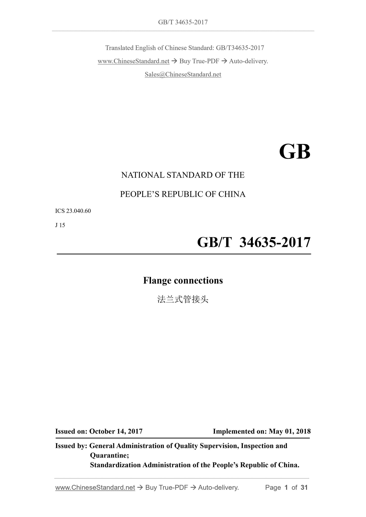
GB/T 34635-2017
GB
NATIONAL STANDARD OF THE
PEOPLE’S REPUBLIC OF CHINA
ICS 23.040.60
J 15
Flange connections
ISSUED ON: OCTOBER 14, 2017
IMPLEMENTED ON: MAY 01, 2018
Issued by: General Administration of Quality Supervision, Inspection and
Quarantine;
Standardization Administration of the People’s Republic of China.
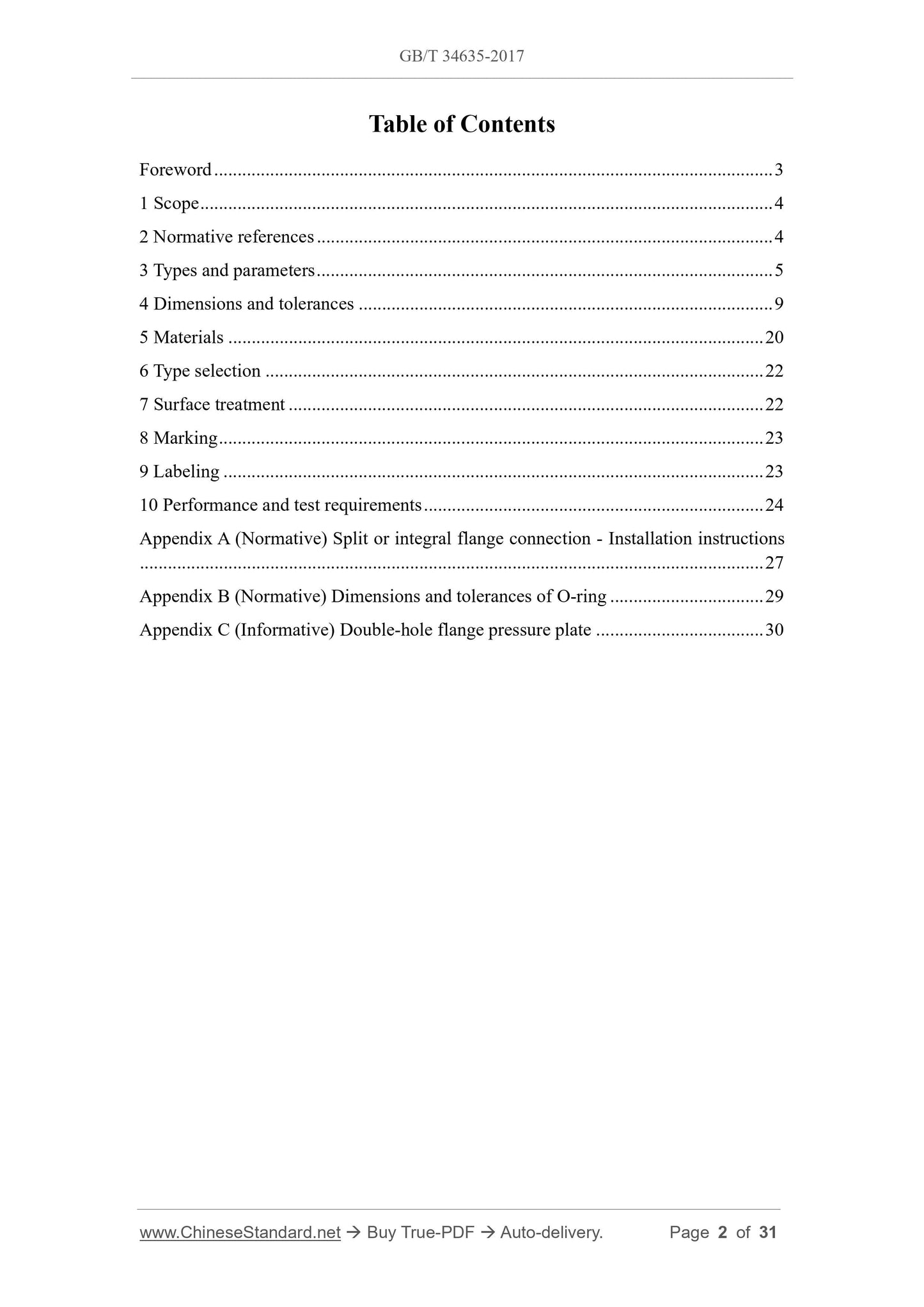
Table of Contents
Foreword ... 3
1 Scope ... 4
2 Normative references ... 4
3 Types and parameters ... 5
4 Dimensions and tolerances ... 9
5 Materials ... 20
6 Type selection ... 22
7 Surface treatment ... 22
8 Marking ... 23
9 Labeling ... 23
10 Performance and test requirements ... 24
Appendix A (Normative) Split or integral flange connection - Installation instructions
... 27
Appendix B (Normative) Dimensions and tolerances of O-ring ... 29
Appendix C (Informative) Double-hole flange pressure plate ... 30
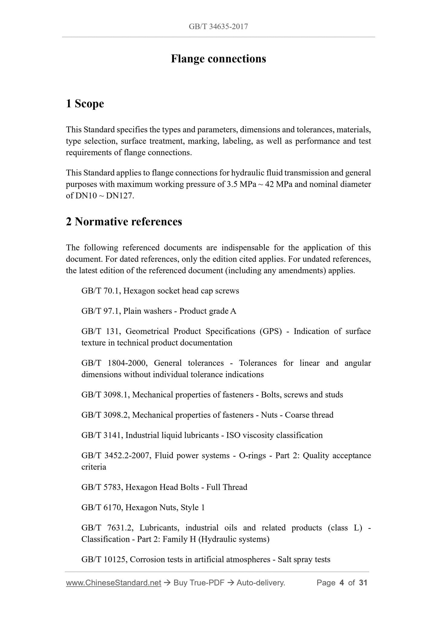
Flange connections
1 Scope
This Standard specifies the types and parameters, dimensions and tolerances, materials,
type selection, surface treatment, marking, labeling, as well as performance and test
requirements of flange connections.
This Standard applies to flange connections for hydraulic fluid transmission and general
purposes with maximum working pressure of 3.5 MPa ~ 42 MPa and nominal diameter
of DN10 ~ DN127.
2 Normative references
The following referenced documents are indispensable for the application of this
document. For dated references, only the edition cited applies. For undated references,
the latest edition of the referenced document (including any amendments) applies.
GB/T 70.1, Hexagon socket head cap screws
GB/T 97.1, Plain washers - Product grade A
GB/T 131, Geometrical Product Specifications (GPS) - Indication of surface
texture in technical product documentation
GB/T 1804-2000, General tolerances - Tolerances for linear and angular
dimensions without individual tolerance indications
GB/T 3098.1, Mechanical properties of fasteners - Bolts, screws and studs
GB/T 3098.2, Mechanical properties of fasteners - Nuts - Coarse thread
GB/T 3141, Industrial liquid lubricants - ISO viscosity classification
GB/T 3452.2-2007, Fluid power systems - O-rings - Part 2: Quality acceptance
criteria
GB/T 5783, Hexagon Head Bolts - Full Thread
GB/T 6170, Hexagon Nuts, Style 1
GB/T 7631.2, Lubricants, industrial oils and related products (class L) -
Classification - Part 2: Family H (Hydraulic systems)
GB/T 10125, Corrosion tests in artificial atmospheres - Salt spray tests
heavy series split or integral flange connections shall comply with the provisions of
Figure 7 and Table 10.
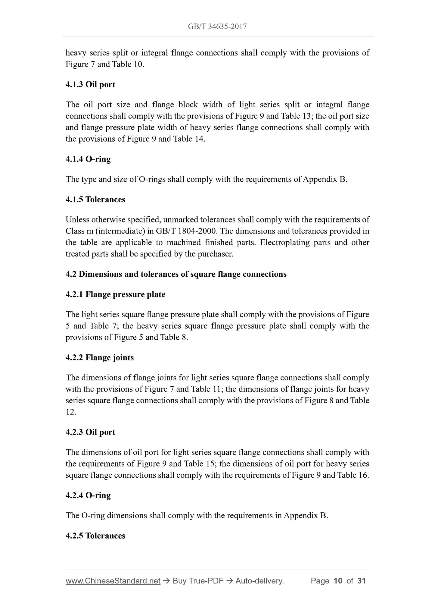
4.1.3 Oil port
The oil port size and flange block width of light series split or integral flange
connections shall comply with the provisions of Figure 9 and Table 13; the oil port size
and flange pressure plate width of heavy series flange connections shall comply with
the provisions of Figure 9 and Table 14.
4.1.4 O-ring
The type and size of O-rings shall comply with the requirements of Appendix B.
4.1.5 Tolerances
Unless otherwise specified, unmarked tolerances shall comply with the requirements of
Class m (intermediate) in GB/T 1804-2000. The dimensions and tolerances provided in
the table are applicable to machined finished parts. Electroplating parts and other
treated parts shall be specified by the purchaser.
4.2 Dimensions and tolerances of square flange connections
4.2.1 Flange pressure plate
The light series square flange pressure plate shall comply with the provisions of Figure
5 and Table 7; the heavy series square flange pressure plate shall comply with the
provisions of Figure 5 and Table 8.
4.2.2 Flange joints
The dimensions of flange joints for light series square flange connections shall comply
with the provisions of Figure 7 and Table 11; the dimensions of flange joints for heavy
series square flange connections shall comply with the provisions of Figure 8 and Table
12.
4.2.3 Oil port
The dimensions of oil port for light series square flange connections shall comply with
the requirements of Figure 9 and Table 15; the dimensions of oil port for heavy series
square flange connections shall comply with the requirements of Figure 9 and Table 16.
4.2.4 O-ring
The O-ring dimensions shall comply with the requirements in Appendix B.
4.2.5 Tolerances
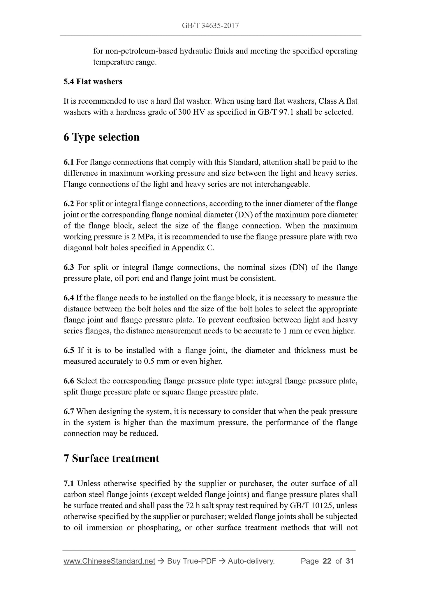
for non-petroleum-based hydraulic fluids and meeting the specified operating
temperature range.
5.4 Flat washers
It is recommended to use a hard flat washer. When using hard flat washers, Class A flat
washers with a hardness grade of 300 HV as specified in GB/T 97.1 shall be selected.
6 Type selection
6.1 For flange connections that comply with this Standard, attention shall be paid to the
difference in maximum working pressure and size between the light and heavy series.
Flange connections of the light and heavy series are not interchangeable.
6.2 For split or integral flange connections, according to the inner diameter of the flange
joint or the corresponding flange nominal diameter (DN) of the maximum pore diameter
of the flange block, select the size of the flange connection. When the maximum
working pressure is 2 MPa, it is recommended to use the flange pressure plate with two
diagonal bolt holes specified in Appendix C.
6.3 For split or integral flange connections, the nominal sizes (DN) of the flange
pressure plate, oil port end and flange joint must be consistent.
6.4 If the flange needs to be installed on the flange block, it is necessary to measure the
distance between the bolt holes and the size of the bolt holes to select the appropriate
flange joint and flange pressure plate. To prevent confusion between light and heavy
series flanges, the distance measurement needs to be accurate to 1 mm or even higher.
6.5 If it is to be installed with a flange joint, the diameter and thickness must be
measured accurately to 0.5 mm or even higher.
6.6 Select the corresponding flange pressure plate type: integral flange pressure plate,
split flange pressure plate or square flange pressure plate.
6.7 When designing the system, it is necessary to consider that when the peak pressure
in the system is higher than the maximum pressure, the performance of the flange
connection may be reduced.
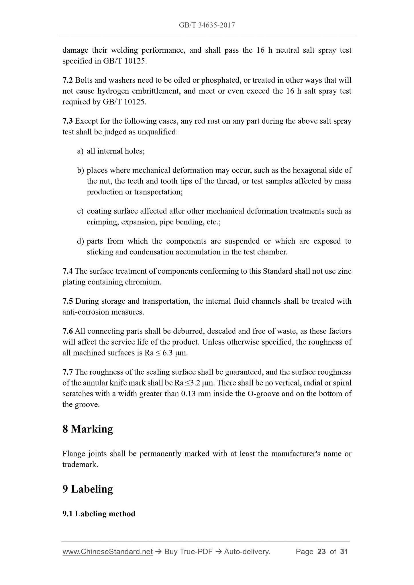
7 Surface treatment
7.1 Unless otherwise specified by the supplier or purchaser, the outer surface of all
carbon steel flange joints (except welded flange joints) and flange pressure plates shall
be surface treated and shall pass the 72 h salt spray test required by GB/T 10125, unless
otherwise specified by the supplier or purchaser; welded flange joints shall be subjected
to oil immersion or phosphating, or other surface treatment methods that will not
damage their welding performance, and shall pass the 16 h neutral salt spray test
specified in GB/T 10125.
7.2 Bolts and washers need to be oiled or phosphated, or treated in other ways that will
not cause hydrogen embrittlement, and meet or even exceed the 16 h salt spray test
required by GB/T 10125.
7.3 Except for the following cases, any red rust on any part during the above salt spray
test shall be judged as unqualified:
a) all internal holes;
b) places where mechanical deformation may occur, such as the hexagonal side of
the nut, the teeth and tooth tips of the thread, or test samples affected by mass
production or transportation;
c) coating surface affected after other mechanical deformation treatments such as
crimping, expansion, pipe bending, etc.;
d) parts from which the components are suspended or which are exposed to
sticking and condensation accumulation in the test chamber.
7.4 The surface treatment of components conforming to this Standard shall not use zinc
plating containing chromium.
7.5 During storage and transportation, the internal fluid channels shall be treated with
anti-corrosion measures.
7.6 All connecting parts shall be deburred, descaled and free of waste, as these factors
will affect the service life of the product. Unless otherwise specified, the roughness of
all machined surfaces is Ra ≤ 6.3 μm.
7.7 The roughness of the sealing surface shall be guaranteed, and the surface roughness
of the annular knife mark shall be Ra ≤3.2 μm. There shall be no vertical, radial or spiral
scratches with a width greater than 0.13 mm inside the O-groove and on the bottom of
the groove.
8 Marking
Flange joints shall be permanently marked with at least the manufacturer's name or
trademark.
9 Labeling
9.1 Labeling method
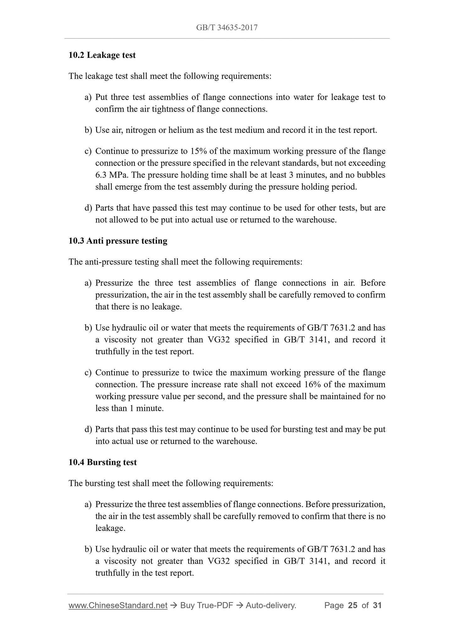
10.2 Leakage test
The leakage test shall meet the following requirements:
a) Put three test assemblies of flange connections into water for leakage test to
confirm the air tightness of flange connections.
b) Use air, nitrogen or helium as the test medium and record it in the test report.
c) Continue to pressurize to 15% of the maximum working pressure of the flange
connection or the pressure specified in the relevant standards, but not exceeding
6.3 MPa. The pressure holding time shall be at least 3 minutes, and no bubbles
shall emerge from the test assembly during the pressure holding period.
d) Parts that have passed this test may continue to be used for other tests, but are
not allowed to be put into actual use or returned to the warehouse.
10.3 Anti pressure testing
The anti-pressure testing shall meet the following requirements:
a) Pressurize the three test assemblies of flange connections in air. Before
pressurization, the air in the test assembly shall be carefully removed to confirm
that there is no leakage.
b) Use hydraulic oil or water that meets the requirements of GB/T 7631.2 and has
a viscosity not greater than VG32 specified in GB/T 3141, and record it
truthfully in the test report.
c) Continue to pressurize to twice the maximum working pressure of the flange
connection. The pressure increase rate shall not exceed 16% of the maximum
working pressure value per second, and the pressure shall be maintained for no
less than 1 minute.
d) Parts that pass this test may continue to be used for bursting test and may be put
into actual use or returned to the warehouse.
10.4 Bursting test
The bursting test shall meet the following requirements:
a) Pressurize the three test assemblies of flange connections. Before pressurization,
the air in the test assembly shall be carefully removed to confirm that there is no
leakage.
b) Use hydraulic oil or water that meets the requirements of GB/T 7631.2 and has
a viscosity not greater than VG32 specified in GB/T 3141, and record it
truthfully in the test report.
GB/T 34635-2017
GB
NATIONAL STANDARD OF THE
PEOPLE’S REPUBLIC OF CHINA
ICS 23.040.60
J 15
Flange connections
ISSUED ON: OCTOBER 14, 2017
IMPLEMENTED ON: MAY 01, 2018
Issued by: General Administration of Quality Supervision, Inspection and
Quarantine;
Standardization Administration of the People’s Republic of China.
Table of Contents
Foreword ... 3
1 Scope ... 4
2 Normative references ... 4
3 Types and parameters ... 5
4 Dimensions and tolerances ... 9
5 Materials ... 20
6 Type selection ... 22
7 Surface treatment ... 22
8 Marking ... 23
9 Labeling ... 23
10 Performance and test requirements ... 24
Appendix A (Normative) Split or integral flange connection - Installation instructions
... 27
Appendix B (Normative) Dimensions and tolerances of O-ring ... 29
Appendix C (Informative) Double-hole flange pressure plate ... 30
Flange connections
1 Scope
This Standard specifies the types and parameters, dimensions and tolerances, materials,
type selection, surface treatment, marking, labeling, as well as performance and test
requirements of flange connections.
This Standard applies to flange connections for hydraulic fluid transmission and general
purposes with maximum working pressure of 3.5 MPa ~ 42 MPa and nominal diameter
of DN10 ~ DN127.
2 Normative references
The following referenced documents are indispensable for the application of this
document. For dated references, only the edition cited applies. For undated references,
the latest edition of the referenced document (including any amendments) applies.
GB/T 70.1, Hexagon socket head cap screws
GB/T 97.1, Plain washers - Product grade A
GB/T 131, Geometrical Product Specifications (GPS) - Indication of surface
texture in technical product documentation
GB/T 1804-2000, General tolerances - Tolerances for linear and angular
dimensions without individual tolerance indications
GB/T 3098.1, Mechanical properties of fasteners - Bolts, screws and studs
GB/T 3098.2, Mechanical properties of fasteners - Nuts - Coarse thread
GB/T 3141, Industrial liquid lubricants - ISO viscosity classification
GB/T 3452.2-2007, Fluid power systems - O-rings - Part 2: Quality acceptance
criteria
GB/T 5783, Hexagon Head Bolts - Full Thread
GB/T 6170, Hexagon Nuts, Style 1
GB/T 7631.2, Lubricants, industrial oils and related products (class L) -
Classification - Part 2: Family H (Hydraulic systems)
GB/T 10125, Corrosion tests in artificial atmospheres - Salt spray tests
heavy series split or integral flange connections shall comply with the provisions of
Figure 7 and Table 10.
4.1.3 Oil port
The oil port size and flange block width of light series split or integral flange
connections shall comply with the provisions of Figure 9 and Table 13; the oil port size
and flange pressure plate width of heavy series flange connections shall comply with
the provisions of Figure 9 and Table 14.
4.1.4 O-ring
The type and size of O-rings shall comply with the requirements of Appendix B.
4.1.5 Tolerances
Unless otherwise specified, unmarked tolerances shall comply with the requirements of
Class m (intermediate) in GB/T 1804-2000. The dimensions and tolerances provided in
the table are applicable to machined finished parts. Electroplating parts and other
treated parts shall be specified by the purchaser.
4.2 Dimensions and tolerances of square flange connection...
View full details