

1
/
of
7
www.ChineseStandard.us -- Field Test Asia Pte. Ltd.
GB/T 34530.2-2017 English PDF (GB/T34530.2-2017)
GB/T 34530.2-2017 English PDF (GB/T34530.2-2017)
Regular price
$150.00
Regular price
Sale price
$150.00
Unit price
/
per
Shipping calculated at checkout.
Couldn't load pickup availability
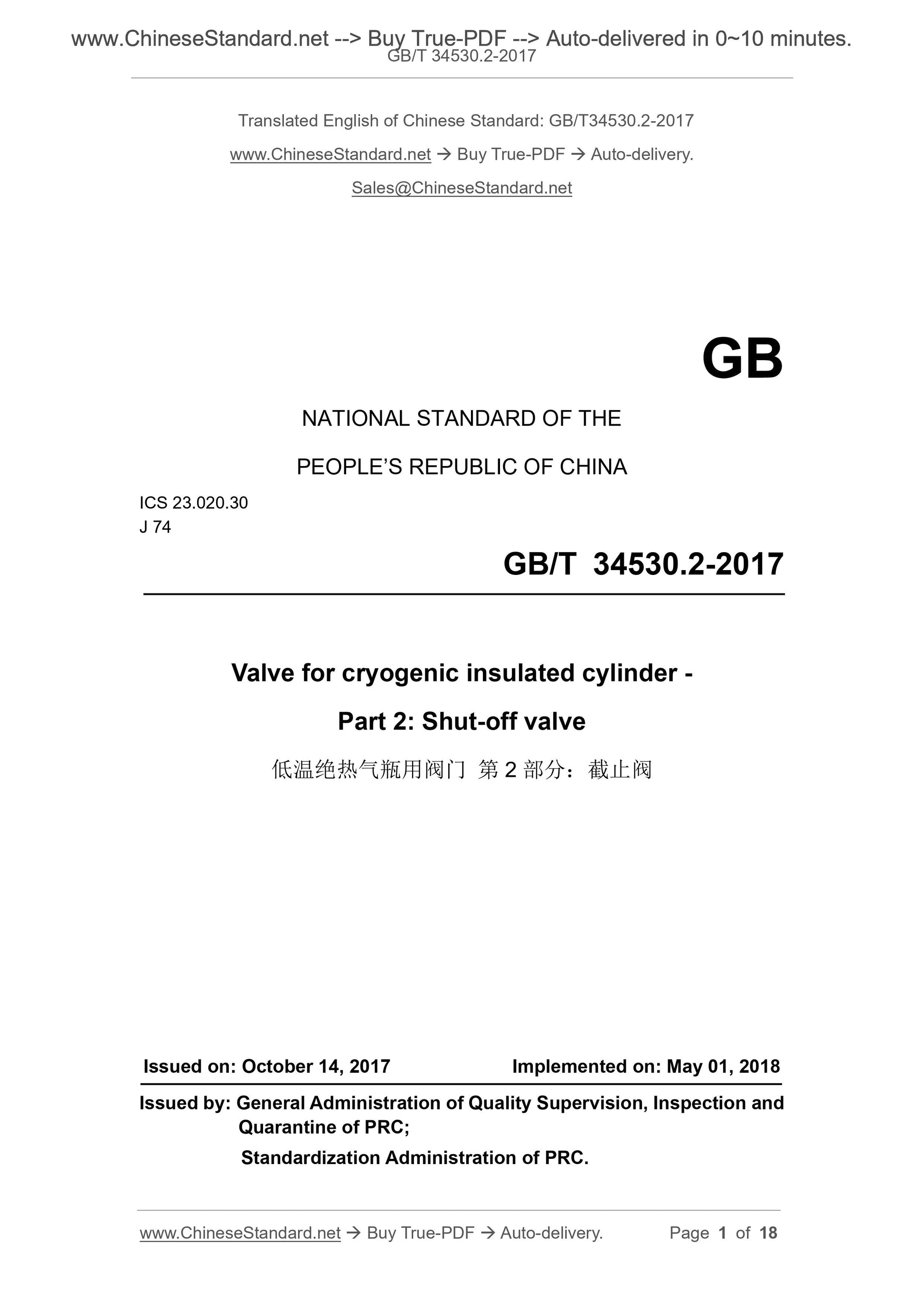
GB/T 34530.2-2017: Valve for cryogenic insulated cylinder - Part 2: Shut-off valve
Delivery: 9 seconds. Download (and Email) true-PDF + Invoice.Get Quotation: Click GB/T 34530.2-2017 (Self-service in 1-minute)
Newer / historical versions: GB/T 34530.2-2017
Preview True-PDF
Scope
This part of GB/T 34530 specifies the basic types, technical requirements, testmethods, inspection rules, marking, packaging, transportation, storage, product
certificate, batch inspection quality certificate of shut-off valves for cryogenic
insulated cylinders (hereinafter referred to as “valves”).
This part applies to the shut-off valve for gas cylinders which contain mediums
such as liquid oxygen, liquid nitrogen, liquid argon, liquefied natural gas, carbon
dioxide, nitrous oxide, have a nominal working pressure of not more than 3.5
MPa, the design temperature of -196 °C ~ +85 °C, the ambient temperature of
-40 °C ~ +60 °C.
Basic Data
| Standard ID | GB/T 34530.2-2017 (GB/T34530.2-2017) |
| Description (Translated English) | Valve for cryogenic insulated cylinder - Part 2: Shut-off valve |
| Sector / Industry | National Standard (Recommended) |
| Classification of Chinese Standard | J74 |
| Classification of International Standard | 23.020.30 |
| Word Count Estimation | 14,116 |
| Date of Issue | 2017-10-14 |
| Date of Implementation | 2018-05-01 |
| Issuing agency(ies) | General Administration of Quality Supervision, Inspection and Quarantine of the People's Republic of China, Standardization Administration of the People's Republic of China |
Share