GB/T 34482-2017 English PDF (GBT34482-2017)
Regular price
$150.00 USD
Regular price
Sale price
$150.00 USD
Unit price
/
per
Delivery: 3 seconds. Download true-PDF + Invoice.
Get QUOTATION in 1-minute: Click GB/T 34482-2017
Historical versions: GB/T 34482-2017
Preview True-PDF (Reload/Scroll if blank)
GB/T 34482-2017: Determination of thermal transmittance for architecture aluminium alloy thermal barrier profiles
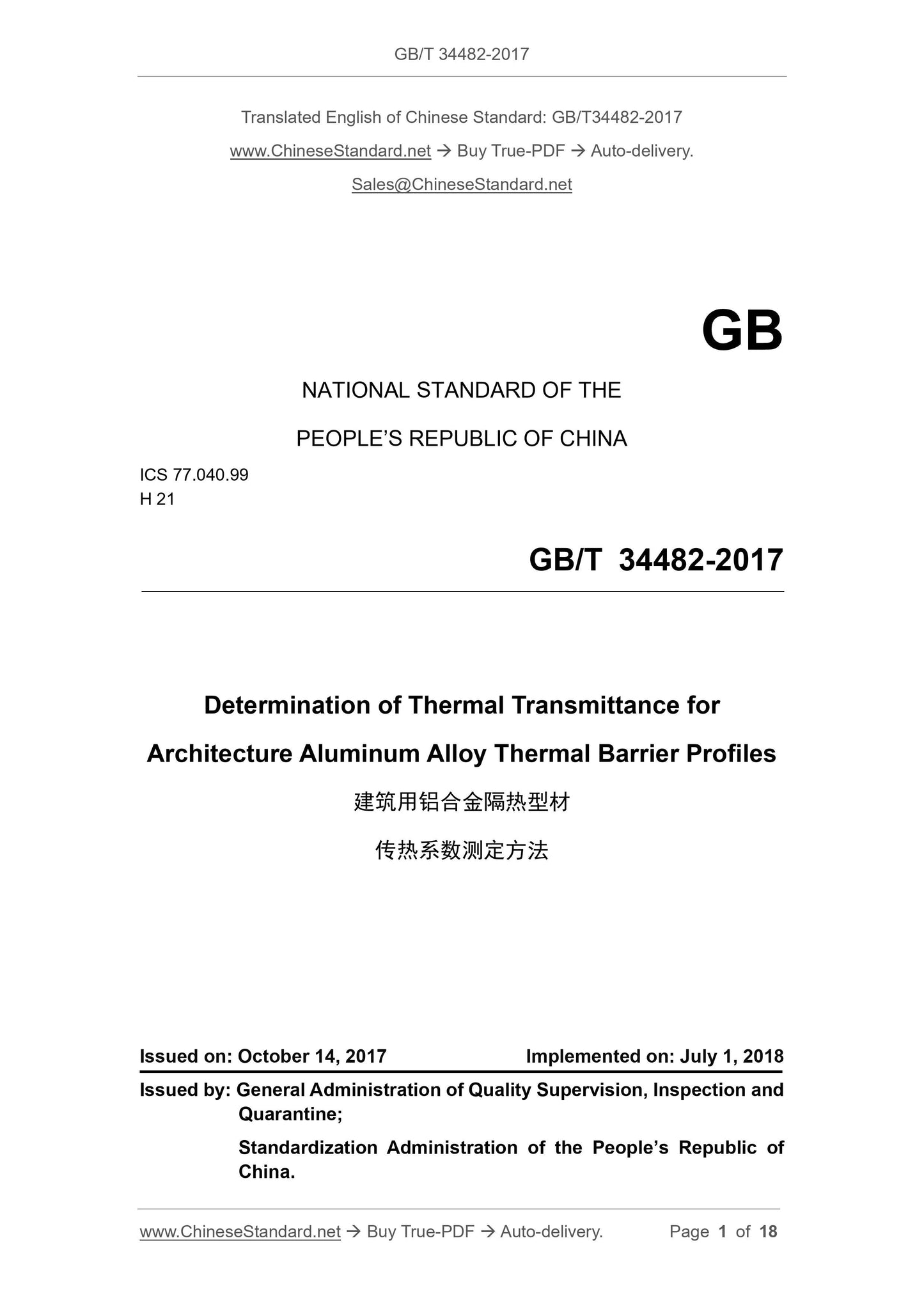
GB/T 34482-2017
NATIONAL STANDARD OF THE
PEOPLE’S REPUBLIC OF CHINA
ICS 77.040.99
H 21
Determination of Thermal Transmittance for
Architecture Aluminum Alloy Thermal Barrier Profiles
ISSUED ON: OCTOBER 14, 2017
IMPLEMENTED ON: JULY 1, 2018
Issued by: General Administration of Quality Supervision, Inspection and
Quarantine;
Standardization Administration of the People’s Republic of
China.
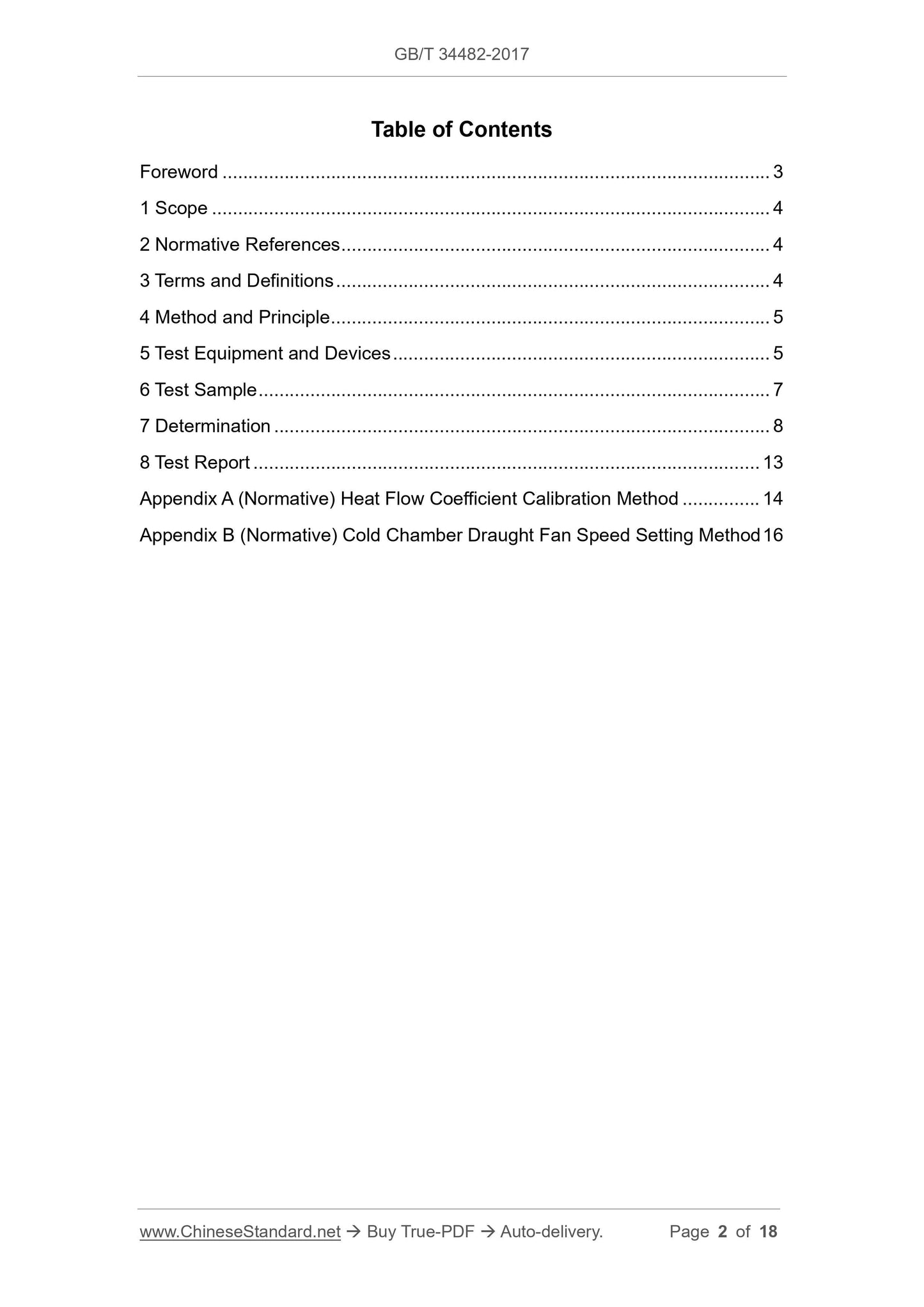
Table of Contents
Foreword ... 3
1 Scope ... 4
2 Normative References ... 4
3 Terms and Definitions ... 4
4 Method and Principle ... 5
5 Test Equipment and Devices ... 5
6 Test Sample ... 7
7 Determination ... 8
8 Test Report ... 13
Appendix A (Normative) Heat Flow Coefficient Calibration Method ... 14
Appendix B (Normative) Cold Chamber Draught Fan Speed Setting Method 16
Determination of Thermal Transmittance for
Architecture Aluminum Alloy Thermal Barrier Profiles
1 Scope
This Standard stipulates the terms, definitions, method and principle, test equipment
and devices, test sample, determination and test report for the determination of thermal
transmittance for architecture aluminum alloy thermal barrier profiles.
This Standard is applicable to the determination of thermal transmittance for
architecture aluminum alloy thermal barrier profiles.
2 Normative References
The following documents are indispensable to the application of this document. In
terms of references with a specific date, only versions with a specific date are
applicable to this document. In terms of references without a specific date, the latest
versions (including all the modification lists) are applicable to this document.
GB/T 4132 Definitions of Terms Relating to Thermal Insulating Materials
GB/T 8170 Rules of Rounding off for Numerical Values and Expression and Judgement
of Limiting Values
GB/T 10294 Thermal Insulation - Determination of Steady-state Thermal Resistance
and Related Properties - Guarded Hot Plate Apparatus
GB/T 13475 Thermal Insulation - Determination of Steady-state Thermal Transmission
Properties - Calibrated and Guard Hot Box
JJG 368-2000 Working Copper/Copper-Nickel Thermocouple
3 Terms and Definitions
Terms and definitions defined in GB/T 4132, and the following terms and definitions
are applicable to this document.
3.1 Areal Density of Heat Flow Rate
Areal density of heat flow rate refers to per unit area heat flow, which is vertical to the
0.04 W/(mK). The actual value of thermal transmittance shall be provided by
manufacturers, or, be determined in accordance with the methods stipulated in GB/T
10294. The parallelism of both sides of the thermal insulation board shall be not more
than ± 0.5°. Thermal insulation board for calibration, which is known as calibration
board for short, has the thickness of 20 mm or 60 mm.
5.4 Test Piece Frame
The texture of test piece frame shall comply with the stipulations in GB/T 13475. The
thermal transmittance shall be not more than 0.04 W/(mK). The thickness of test piece
frame shall be not less than 300 mm.
5.5 Hot Box External Wall
The texture of hot box external wall shall comply with the stipulations in GB/T 13475.
The thermal transmittance shall be not more than 0.04 W/(mK). The thickness of hot
box external wall shall be not less than 200 mm.
5.6 Hot Box Calibration
5.6.1 Parameters that the hot box needs to calibrate include: hot chamber external wall
heat flow coefficient M1 and test piece frame heat flow coefficient M2.
5.6.2 When the cold chamber draught fan of the hot box is constant-speed fan, the
wind speed of the cold chamber draught fan shall be 3 m/s. In accordance with the
methods in Appendix A, calibrate hot chamber external wall heat flow coefficient M1
and test piece frame heat flow coefficient M2.
5.6.3 When the cold chamber draught fan of the hot box is adjustable-speed fan, in
accordance with the methods in Appendix B, set up the wind speed. Then, in
accordance with the methods in Appendix A, calibrate hot chamber external wall heat
flow coefficient M1 and test piece frame heat flow coefficient M2.
5.6.4 Hot box calibration shall be conducted at least once a year. If the location,
structure or accessory of hot box changes, re-calibration will be needed.
6 Test Sample
In accordance with hot box’s hole size, cut-take samples. The cutting inclination of the
samples shall be ± 0.5°. The total effective projected area of the samples shall be not
less than 30% of the hole area of the hot box. The effective projected area of sample
refers to the larger one in the projected areas of both-side metal profile, indoors and
outdoors, of the thermal barrier profile. Please refer to Figure 2 for the selection of
effective projected area Af of an individual sample. The sum of effective projected areas
of multiple samples adopted in one test shall be considered as the total effective
projected area of the samples.
various measured parameters (energy consumption value of maintaining constant hot
chamber temperature; internal and external surface temperature of hot chamber
external wall; temperature of test piece frame hot side surface and cold side surface;
air temperature of hot chamber and cold chamber; temperature of thermal insulation
board hot side surface and cold side surface) as a group of data.
7.6 Result Calculation
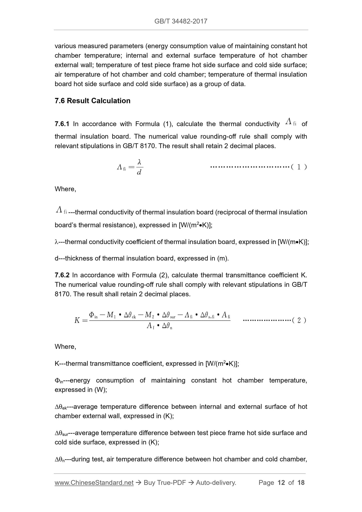
7.6.1 In accordance with Formula (1), calculate the thermal conductivity of
thermal insulation board. The numerical value rounding-off rule shall comply with
relevant stipulations in GB/T 8170. The result shall retain 2 decimal places.
Where,
---thermal conductivity of thermal insulation board (reciprocal of thermal insulation
board’s thermal resistance), expressed in [W/(m2K)];
---thermal conductivity coefficient of thermal insulation board, expressed in [W/(mK)];
d---thickness of thermal insulation board, expressed in (m).
7.6.2 In accordance with Formula (2), calculate thermal transmittance coefficient K.
The numerical value rounding-off rule shall comply with relevant stipulations in GB/T
8170. The result shall retain 2 decimal places.
Where,
K---thermal transmittance coefficient, expressed in [W/(m2K)];
in---energy consumption of maintaining constant hot chamber temperature,
expressed in (W);
ek---average temperature difference between internal and external surface of hot
chamber external wall, expressed in (K);
sur---average temperature difference between test piece frame hot side surface and
cold side surface, expressed in (K);
n---during test, air temperature difference between hot chamber and cold chamber,
Appendix A
(Normative)
Heat Flow Coefficient Calibration Method
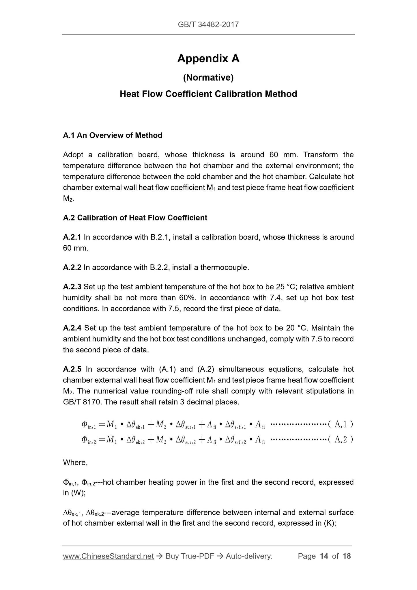
A.1 An Overview of Method
Adopt a calibration board, whose thickness is around 60 mm. Transform the
temperature difference between the hot chamber and the external environment; the
temperature difference between the cold chamber and the hot chamber. Calculate hot
chamber external wall heat flow coefficient M1 and test piece frame heat flow coefficient
M2.
A.2 Calibration of Heat Flow Coefficient
A.2.1 In accordance with B.2.1, install a calibration board, whose thickness is around
60 mm.
A.2.2 In accordance with B.2.2, install a thermocouple.
A.2.3 Set up the test ambient temperature of the hot box to be 25 °C; relative ambient
humidity shall be not more than 60%. In accordance with 7.4, set up hot box test
conditions. In accordance with 7.5, record the first piece of data.
A.2.4 Set ...