1
/
of
6
PayPal, credit cards. Download editable-PDF and invoice in 1 second!
GB/T 34007-2017 English PDF (GBT34007-2017)
Regular price
$145.00 USD
Regular price
Sale price
$145.00 USD
Unit price
/
per
Shipping calculated at checkout.
Couldn't load pickup availability
Delivery: 3 seconds. Download true-PDF + Invoice.
Get Quotation: Click GB/T 34007-2017 (Self-service in 1-minute)
Historical versions (Master-website): GB/T 34007-2017
Preview True-PDF (Reload/Scroll-down if blank)
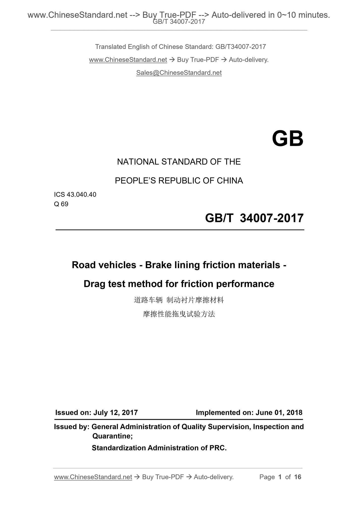
GB/T 34007-2017: Road vehicles - Brake lining friction materials - Drag test method for friction performance
GB/T 34007-2017
Road vehicles--Brake lining friction materials--Drag test method for friction performance
ICS 43.040.40
Q69
National Standards of People's Republic of China
Road vehicle brake lining friction material
Friction performance drag test method
Released on.2017-07-12
2018-06-01 implementation
General Administration of Quality Supervision, Inspection and Quarantine of the People's Republic of China
China National Standardization Administration issued
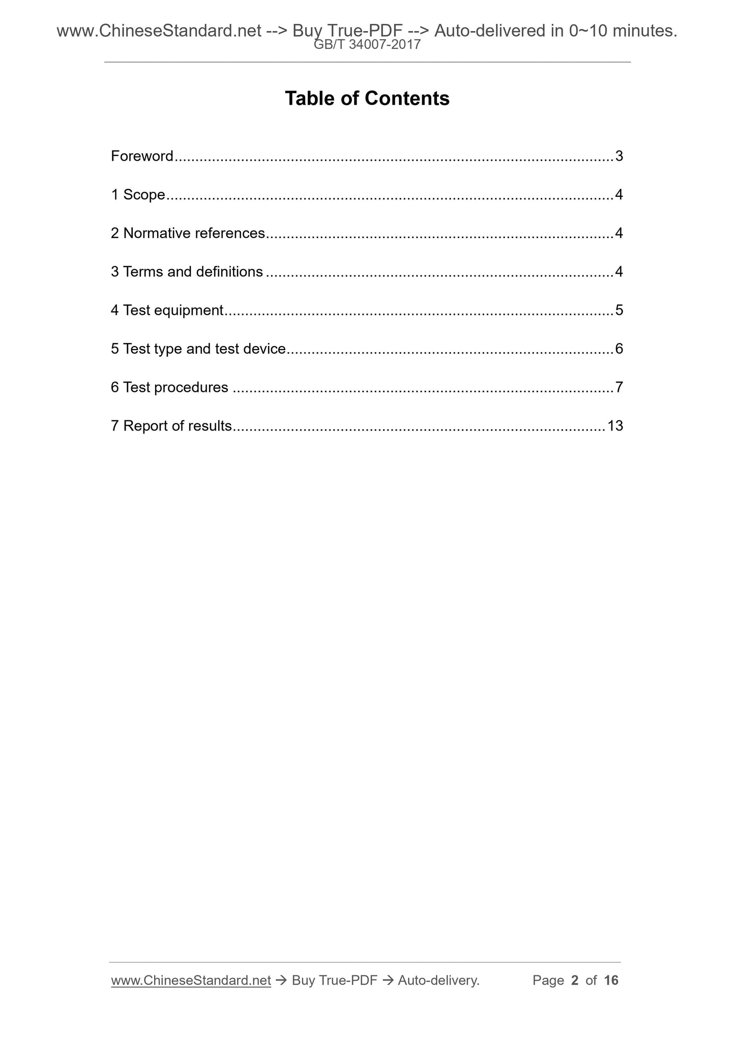
Foreword
This standard was drafted in accordance with the rules given in GB/T 1.1-2009.
This standard was proposed by the China Building Materials Federation.
This standard is under the jurisdiction of the National Non-metallic Mineral Products and Products Standardization Technical Committee (SAC/TC406).
This standard was drafted. Dongying Baofeng Auto Parts Co., Ltd., Jinan Jin Qilin Brake System Co., Ltd., Taimington friction material technology
Technology (Shanghai) Co., Ltd., Fujian Huari Auto Parts Co., Ltd., Xiamen Lixingda Friction Material Co., Ltd., Chongqing Hongyu Friction Products
Company, Shandong Liangshan Shenli Auto Parts Co., Ltd., Ningguo Feiying Auto Parts Co., Ltd., Tonglu Yuxin Auto Parts Co., Ltd.
Division, Xianyang Non-Metallic Mineral Research and Design Institute Co., Ltd., National Non-metallic Mineral Products Quality Supervision and Inspection Center.
The main drafters of this standard. Chen Kewen, Tian Shiguo, Sun Peng, Yan Minghui, Zhang Jianshe, Su Meizhen, Yang Lijun, Ye Jialing, Zhao Yong, Feng Jingyou,
Sun Qichun, Wang Xiaopeng, Shi Zhigang.
Road vehicle brake lining friction material
Friction performance drag test method
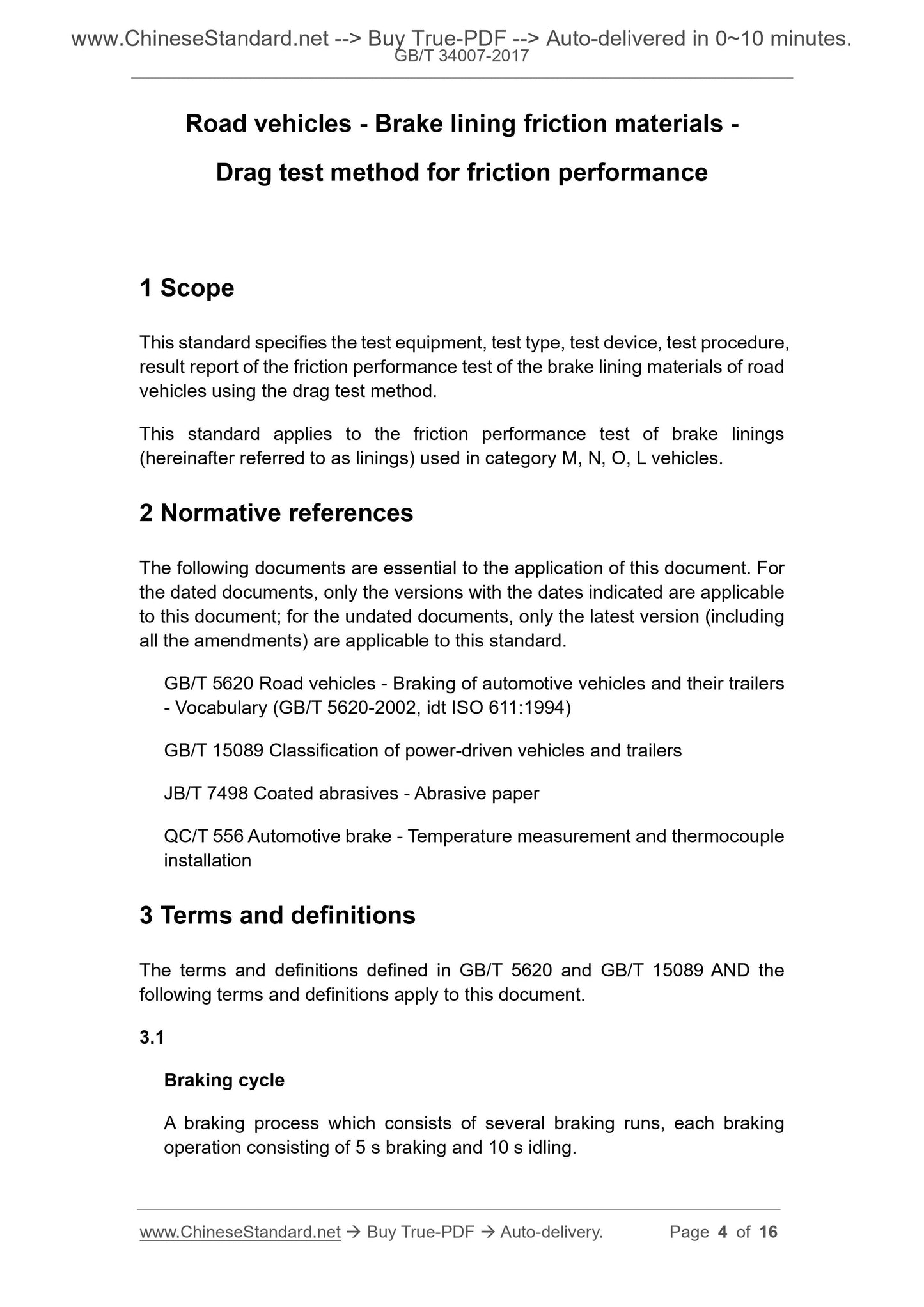
1 Scope
This standard specifies the test equipment and test type for the friction performance test of the brake lining friction material of road vehicles by towing method.
Report with test equipment, test procedures and results.
This standard applies to the friction performance test of brake linings (hereinafter referred to as linings) used in M, N, O and L vehicles.
2 Normative references
The following documents are indispensable for the application of this document. For dated references, only the dated version applies to this article.
Pieces. For undated references, the latest edition (including all amendments) applies to this document.
GB/T 5620 Road vehicle and trailer brake terminology and its definition (GB/T 5620-2002, idtISO 611.
1994)
GB/T 15089 Motor vehicle and trailer classification
JB/T 7498 coated abrasive sandpaper
QC/T 556 Automotive Brake Temperature Measurement and Thermocouple Installation
3 Terms and definitions
The following terms and definitions defined in GB/T 5620 and GB/T 15089 apply to this document.
3.1
Braking cycle
A braking process consisting of several braking runs, each braking operation consisting of 5 s braking and 10 s idling.
3.2
Constant pressure mode constantpressuremode
The control method in which the line pressure remains constant during braking.
3.3
Constant torque mode constanttorquemode
The control method in which the braking torque remains constant during braking.
3.4
Brake disc initial temperature initialbrakerotortemperature
The temperature of the brake disc at the beginning of the first brake run of each brake cycle.
3.5
Brake disc maximum temperature maximumbrakerotortemperature
The temperature exceeded by the brake disc is not allowed during each braking cycle.
4 test equipment
4.1 The test equipment shall be capable of performing pre-set test procedures and achieving automatic control.
4.2 The recording equipment shall be capable of continuously recording the following parameters, and the measurement accuracy shall meet the following requirements.
---Brake output torque, ±1.5%;
---Input line pressure, ±1.5%;
--- Brake disc temperature, ± 1.5%.
4.3 The cooling during the test is air cooled, the temperature of the cooling air does not exceed 25 ° C, and the air flow rate is (600 ± 60) m3/h.
Blow to the brakes.
4.4 The speed of the equipment spindle should be (660 ± 10) r/min when idling, and not less than 600r/min at full load.
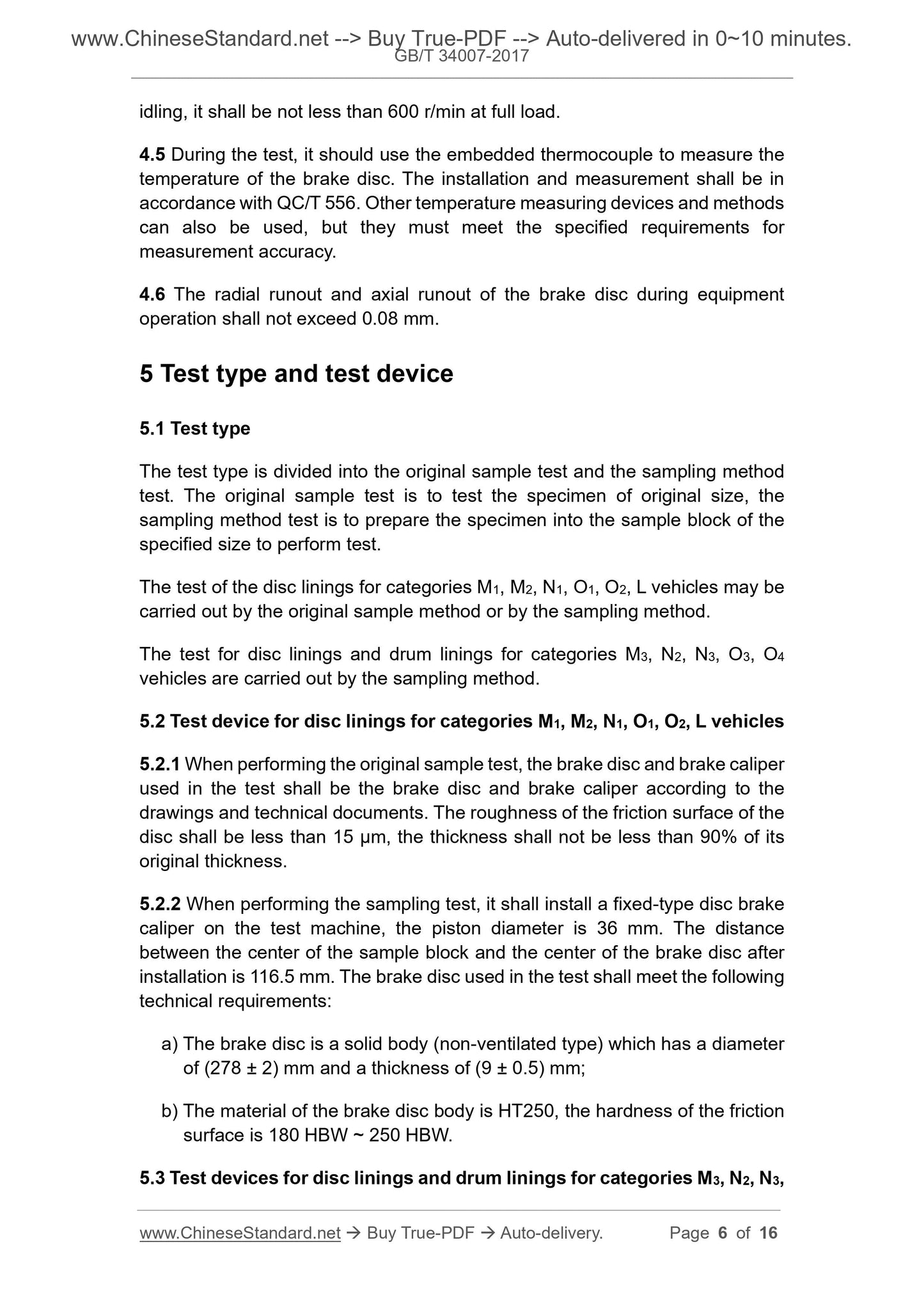
4.5 The embedded thermocouple should be used to measure the temperature of the brake disc during the test. The installation and measurement should be in accordance with QC/T 556. and also
Other temperature measuring devices and methods can be used, but they must meet the specified measurement accuracy requirements.
4.6 The radial runout and axial runout of the brake disc during operation shall not exceed 0.08 mm.
5 Test type and test device
5.1 Test type
The test type is divided into the original sample test and the sampling method test. The original sample test is to test the original size sample, and the sampling method test is to test
Samples of the specified size were tested.
The test of the disc linings for M1, M2, N1, O1, O2 and L vehicles may be carried out by the original method or by the sampling method.
The test for disc linings and drum linings for M3, N2, N3, O3, O4 vehicles was tested by sampling method.
5.2 Test device for disc linings for M1, M2, N1, O1, O2 and L vehicles
5.2.1 When performing the original test, the brake discs and brake calipers used in the test shall be brake discs and brakes in accordance with the drawings and technical documents.
The friction of the friction surface of the brake disc should be less than 15μm and the thickness should be no less than 90% of its original thickness.
5.2.2 When performing the sampling test, a fixed disc brake caliper shall be installed on the test machine with a piston diameter of 36 mm.
The distance between the center of the block and the center of the brake disc is 116.5 mm. The brake disc used in the test shall meet the following technical requirements.
a) The brake disc is a solid body (non-ventilated type) with a diameter of (278 ± 2) mm and a thickness of (9 ± 0.5) mm;
b) The material of the brake disc body is HT250, and the hardness of the friction surface is 180HBW~250HBW.
5.3 Test apparatus for disc linings and drum linings for M3, N2, N3, O3, O4 vehicles
A fixed disc brake caliper shall be installed on the test machine with a piston diameter of 60 mm. After installation, the center of the sample block and the center of the brake disc
The distance is 108mm. The brake disc used in the test shall meet the following technical requirements.
a) The brake disc is a solid body (non-ventilated type) with a diameter of (278 ± 2) mm and a thickness of (12 ± 0.5) mm;
b) The material of the brake disc body is HT250, and the hardness of the friction surface is 180HBW~250HBW.
6 test steps
6.1 Test procedure for disc linings for M1, M2, N1, O1, O2 and L vehicles
6.1.1 Test preparation
6.1.1.1 Determination of test pressure and moment by original method
6.1.1.1.1 Determination of pressure in constant pressure mode
The unit pressure p of the lining friction surface is calculated according to formula (1).
p=
Md
0.057×rw×Ak
(1)
In the formula.
p --- lining friction surface unit pressure, the unit is megapascals (MPa);
Ak---the area of the brake caliper piston in square centimeters (cm2);
Rw --- The effective radius of the brake disc, in millimeters (mm), calculated according to equation (2).
Rw=
Dh
twenty one
(2)
In the formula.
D---The diameter of the brake disc, in millimeters (mm);
h --- The height of the lining in millimeters (mm).
When Ak≤18.1cm2, Md=150N·m; when Ak>18.1cm2, Md=300N·m.
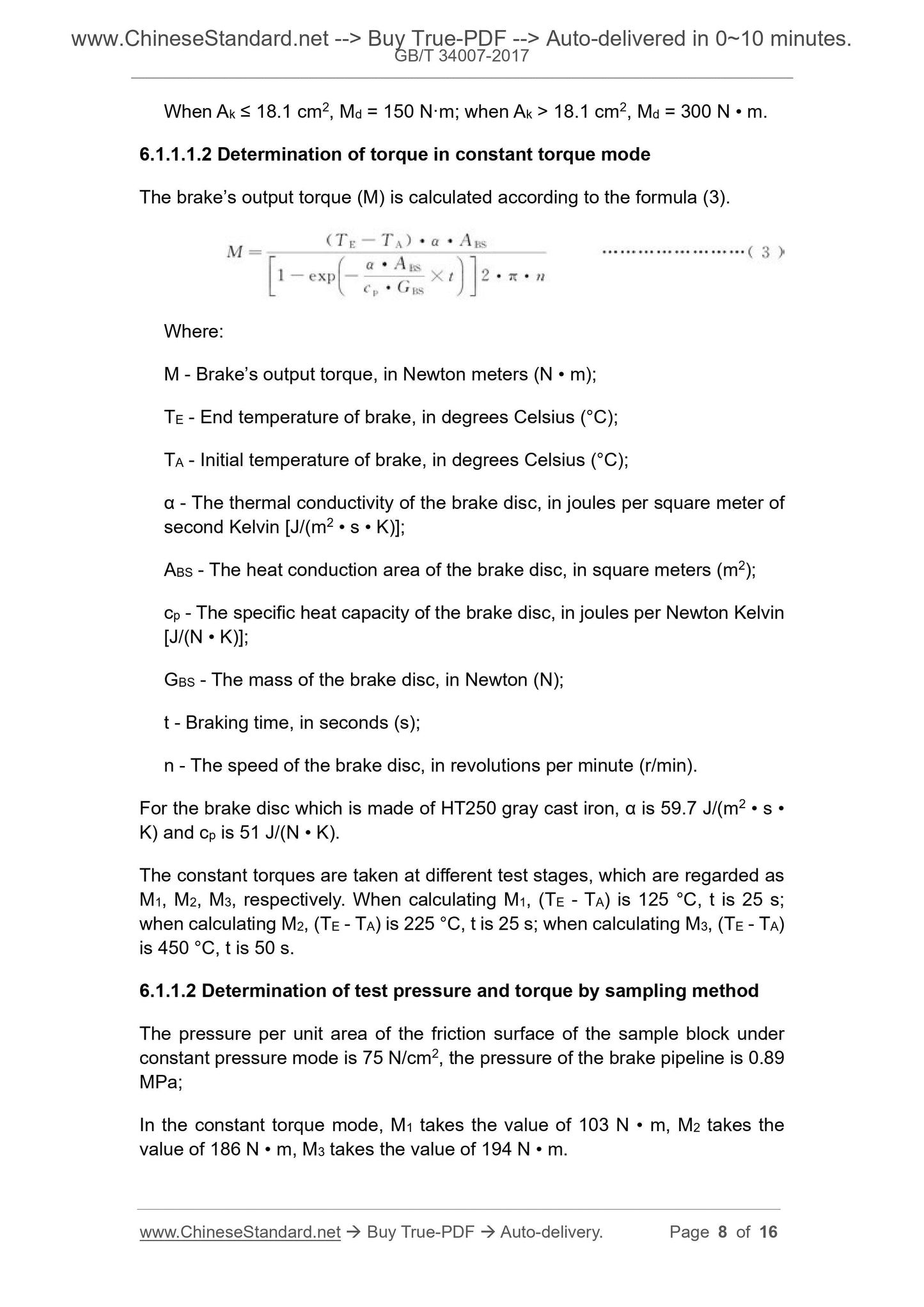
6.1.1.1.2 Determination of torque in constant torque mode
The brake output torque (M) is calculated according to equation (3).
M =
(TE-TA)·α·ABS
1-exp-
α·ABS
Cp·GB S
×t
Êê
Úú2·π·n
(3)
In the formula.
M --- brake output torque in Newton meters (N·m);
TE --- brake end temperature in degrees Celsius (°C);
TA --- brake initial temperature, the unit is Celsius (°C);
α --- Thermal conductivity of the brake disc, in joules per square meter of second Kelvin [J/(m2 · s · K)];
ABS --- heat conduction area of the brake disc, in square meters (m2);
Cp --- specific heat capacity of the brake disc, the unit is Joule per Newton Kelvin [J/(N · K)];
GB S --- brake disc quality in Newton (N);
t --- Braking time in seconds (s);
n --- The speed of the brake disc in revolutions per minute (r/min).
For gray cast iron with brake disc material HT250, α is 59.7J/(m2·s·K), and cp is 51J/(N·K).
The constant moments were taken at different test stages and were counted as M1, M2 and M3, respectively. When calculating M1, (TE-TA) is 125 °C,
t is 25 s; when calculating M2, (TE-TA) is 225 ° C, t is 25 s; when calculating M3, (TE-TA) is 450 ° C, t is 50 s.
6.1.1.2 Determination of test pressure and moment by sampling method
The pressure per unit area of the friction surface of the sample block under constant pressure mode is 75N/cm2, and the pressure of the brake line is 0.89MPa;
In the constant torque mode, M1 takes the value of 103N·m, M2 takes the value of 186N·m, and M3 takes the value of 194N·m.
6.1.1.3 Treatment of the surface of the brake disc
Before each test, the surface of the brake disc should be treated with sandpaper of P240 or finer in JB/T 7498, so that the surface of the brake disc is not obvious.
Wear marks and rust; remove dust and oil from the surface of the brake disc with a soft cloth and absolute ethanol.
6.1.1.4 Sample preparation
6.1.1.4.1 Sample preparation for the original method test
Two linings were randomly drawn from the sample and four points were identified on the back of each lining to determine the position of the lining thickness measurement point, see Figure 1.
Care should be taken to avoid oil, water, stains or breakage on the friction surface of the lining.
Figure 1 Schematic diagram of the position of the thickness measurement point of the original film
6.1.1.4.2 Sample preparation for sampling method test
Two linings were randomly selected from the samples, and each length from the middle of each lining was (40.0±0.2) mm and the width was (30.0±).
0.2) mm, the thickness of the sample is not less than 5.0mm, tightly embedded in the special back plate; if the lining is small, 40mm × 30mm can not be taken
For the sample, two linings can be extracted and assembled into the specified size with two small pieces. The difference in thickness between two small samples should not exceed
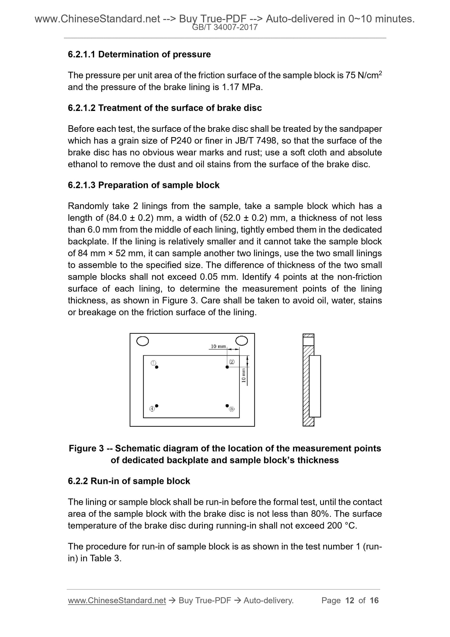
0.05mm. Identify 4 points on the non-friction surface of each sample to determine the position of the sample thickness measurement point, see Figure 2. Should pay attention to avoiding
Rub the face with oil, water, stains or breakage.
Figure 2 Schematic diagram of the sampling method for the backsheet and sample thickness measurement points
6.1.2 Run-in of the lining or sample
The lining or sample should be run-fit before the formal test, and the contact area of the lining or sample with the brake disc should be no less than 80%. Running-in process
The surface temperature of the middle brake disc should not exceed.200 °C.
The procedure for lining or sample running-in is shown in Test No. 1 (run-in) in Tables 1 and 2.
6.1.3 Measurement of initial thickness and mass
Take out the lapped lining or sample, measure and record the thickness of each measuring point of each lining or sample, to the nearest 0.01mm;
Weigh and record the quality of each lining or sample to the nearest 0.01g.
6.1.4 Test procedure
6.1.4.1 Constant pressure mode test procedure
The test procedure for constant pressure mode is shown in Table 1.
Table 1 Test procedure for constant pressure mode of disc lining or sample for M1, M2, N1, O1, O2 and L vehicles
Test number brake cycle number
For each brake cycle
Brake operation times
Brake disc initial
Temperature/°C
Brake disc highest
Temperature/°C
Forced cooling
1 (run-in) ≤6 5
The first brake cycle
≤50, and later 100
200 is
2 1 10 ≤60 no limit
3 5 10 100 no limit (350) a no
4 1 10 100 is not limited to
a For Class L vehicles, this temperature should be limited to 350 °C. If necessary, the number of brake operations per brake cycle can be reduced accordingly, but the brake cycle needs to be increased.
The number of rings is kept constant for the total number of brake runs.
6.1.4.2 Constant torque mode test procedure
The constant torque mode test procedure is shown in Table 2.
Table 2 Test procedure for constant torque mode of disc lining or sample for M1, M2, N1, O1, O2 and L vehicles
Test number brake cycle number
For each brake cycle
Brake operation times
Brake disc initial
Temperature/°C
Brake disc highest
Temperature/°C
Forced cooling constant torque b
1 (run-in) ≤6 5
The first brake cycle
≤50, and later 100
300 is M1
2 1 5 ≤60 350(250)a no M2
3 3 5 100 350 (250) No M2
4 1 10 100 600(350) No M3
5 4 5 100 350 (250) No M2
6 1 10 100 600(350) No M3
7 3 5 100 350 (250) No M2
8 1 5 ≤60 350(250) No M2
a For L-type vehicles, use the numbers in parentheses.
b For the original test, the value of the constant torque is calculated according to 6.1.1.1.2; when the test is carried out, the constant torque is taken according to 6.1.1.2.
6.1.5 Measurement of final thickness and mass
Remove the test lining or sample and measure the thickness and mass according to 6.1.3 and record.
6.2 Test procedure for disc linings and drum linings for M3, N2, N3, O3, O4 vehicles
6.2.1 Test preparation
6.2.1.1 Determination of pressure
The pressure per unit area of the friction surface of the sample block is 75 N/cm 2 and the pressure of the brake line is 1.17 MPa.
6.2.1.2 Treatment of the surface of the brake disc
Before each test, the surface of the brake disc should be treated with sandpaper of P240 or finer in JB/T 7498, so that the surface of the brake disc is not obvious.
Wear marks and rust; remove dust and oil from the surface of the brake disc with a soft cloth and absolute ethanol.
6.2.1.3 Sample preparation
Two linings were randomly selected from the samples, and each length from the middle of each lining was (84.0±0.2) mm and the width was (52.0±).
0.2) mm, the thickness of the sample is not less than 6.0mm, tightly embedded in the special back plate; if the lining is small, can not take 84m...
Share