1
/
of
4
www.ChineseStandard.us -- Field Test Asia Pte. Ltd.
GB/T 33819-2017 English PDF (GB/T33819-2017)
GB/T 33819-2017 English PDF (GB/T33819-2017)
Regular price
$150.00
Regular price
Sale price
$150.00
Unit price
/
per
Shipping calculated at checkout.
Couldn't load pickup availability
GB/T 33819-2017: Hard metal -- Palmqvist toughness test
Delivery: 9 seconds. Download (and Email) true-PDF + Invoice.Get Quotation: Click GB/T 33819-2017 (Self-service in 1-minute)
Newer / historical versions: GB/T 33819-2017
Preview True-PDF
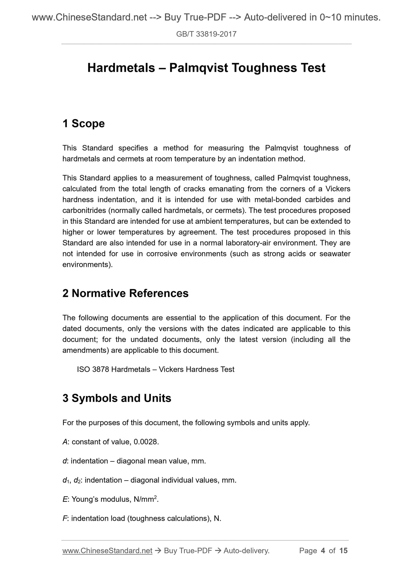
Scope
This standard specifies the method for testing the Barcolage toughness of cemented carbide and cermet by indentation at room temperature.This standard applies to the testing of metal-bonded carbides and carbonitrides (often referred to as cemented carbide or cermet).
The toughness is calculated by testing the total length of the cracks emitted from the apex angles of the Vickers hardness indentations. The test procedure proposed in this standard is usually
It is carried out at room temperature and can be extended to test at high or low temperatures if agreed. The test procedure proposed in this standard is used in the routine laboratory air ring.
Conducted in the environment; not in corrosive environments such as strong acid or seawater environments.
Basic Data
| Standard ID | GB/T 33819-2017 (GB/T33819-2017) |
| Description (Translated English) | Hard metal -- Palmqvist toughness test |
| Sector / Industry | National Standard (Recommended) |
| Classification of Chinese Standard | H16 |
| Classification of International Standard | 77.160 |
| Word Count Estimation | 12,121 |
| Date of Issue | 2017-05-31 |
| Date of Implementation | 2017-12-01 |
| Quoted Standard | ISO 3878 |
| Adopted Standard | ISO 28079-2009, IDT |
| Issuing agency(ies) | General Administration of Quality Supervision, Inspection and Quarantine of the People's Republic of China, Standardization Administration of the People's Republic of China |
| Summary | This standard specifies the use of indentation at room temperature test of cemented carbide and cermet bainite toughness method. This standard applies to the testing of metal-bonded carbides and carbonitrides (often referred to as cemented carbide or cermet) Pasteur's toughness, Pasteur's toughness by testing the Vickers hardness indentation of each vertex divergence of the total length of the crack Calculated. The test procedure proposed in this standard is usually carried out at room temperature, if the agreement can be extended to high temperature or low temperature test. The test procedure proposed in this standard is carried out in a conventional laboratory air environment; it is not carried out in corrosive environments such as strong acids or seawater environments. |
Share