GB/T 3323.2-2019 English PDF (GBT3323.2-2019)
Regular price
$640.00 USD
Regular price
Sale price
$640.00 USD
Unit price
/
per
Delivery: 3 seconds. Download true-PDF + Invoice.
Get QUOTATION in 1-minute: Click GB/T 3323.2-2019
Historical versions: GB/T 3323.2-2019
Preview True-PDF (Reload/Scroll if blank)
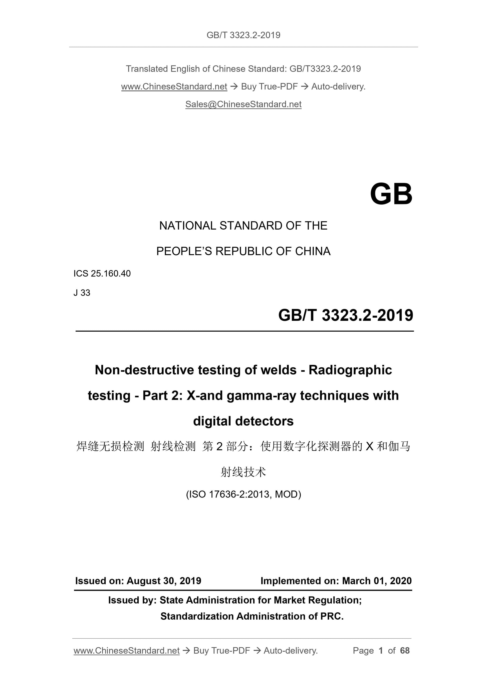
GB/T 3323.2-2019: Non-destructive testing of welds -- Radiographic testing -- Part 2: X-and gamma-ray techniques with digital detectors
GB/T 3323.2-2019
GB
NATIONAL STANDARD OF THE
PEOPLE’S REPUBLIC OF CHINA
ICS 25.160.40
J 33
Non-destructive testing of welds - Radiographic
testing - Part 2: X-and gamma-ray techniques with
digital detectors
(ISO 17636-2:2013, MOD)
ISSUED ON: AUGUST 30, 2019
IMPLEMENTED ON: MARCH 01, 2020
Issued by: State Administration for Market Regulation;
Standardization Administration of PRC.
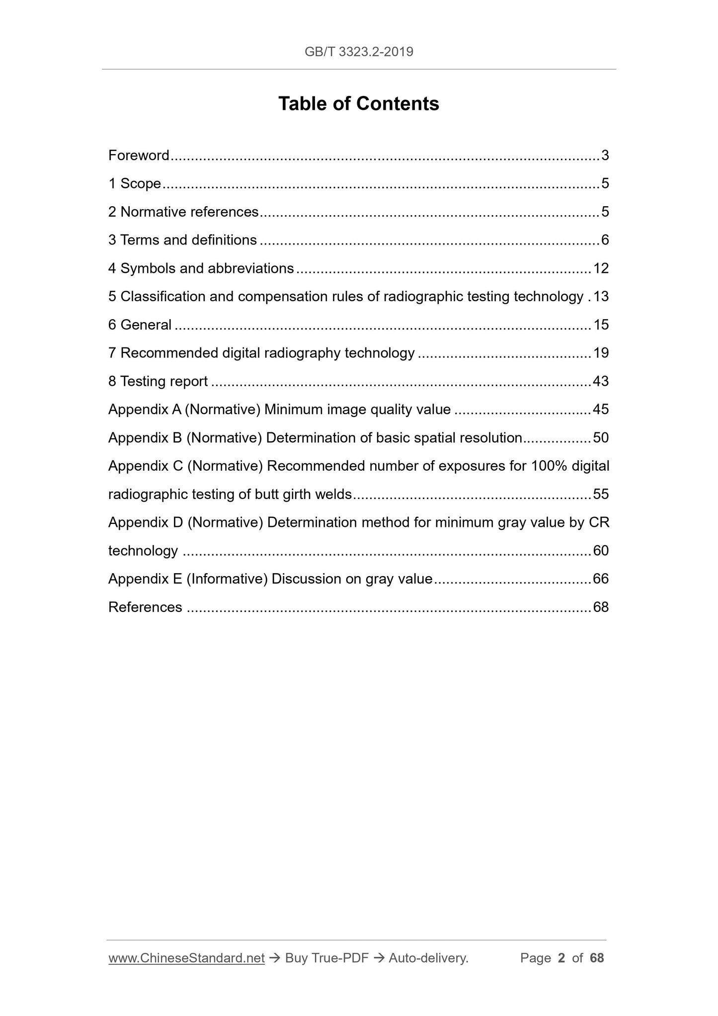
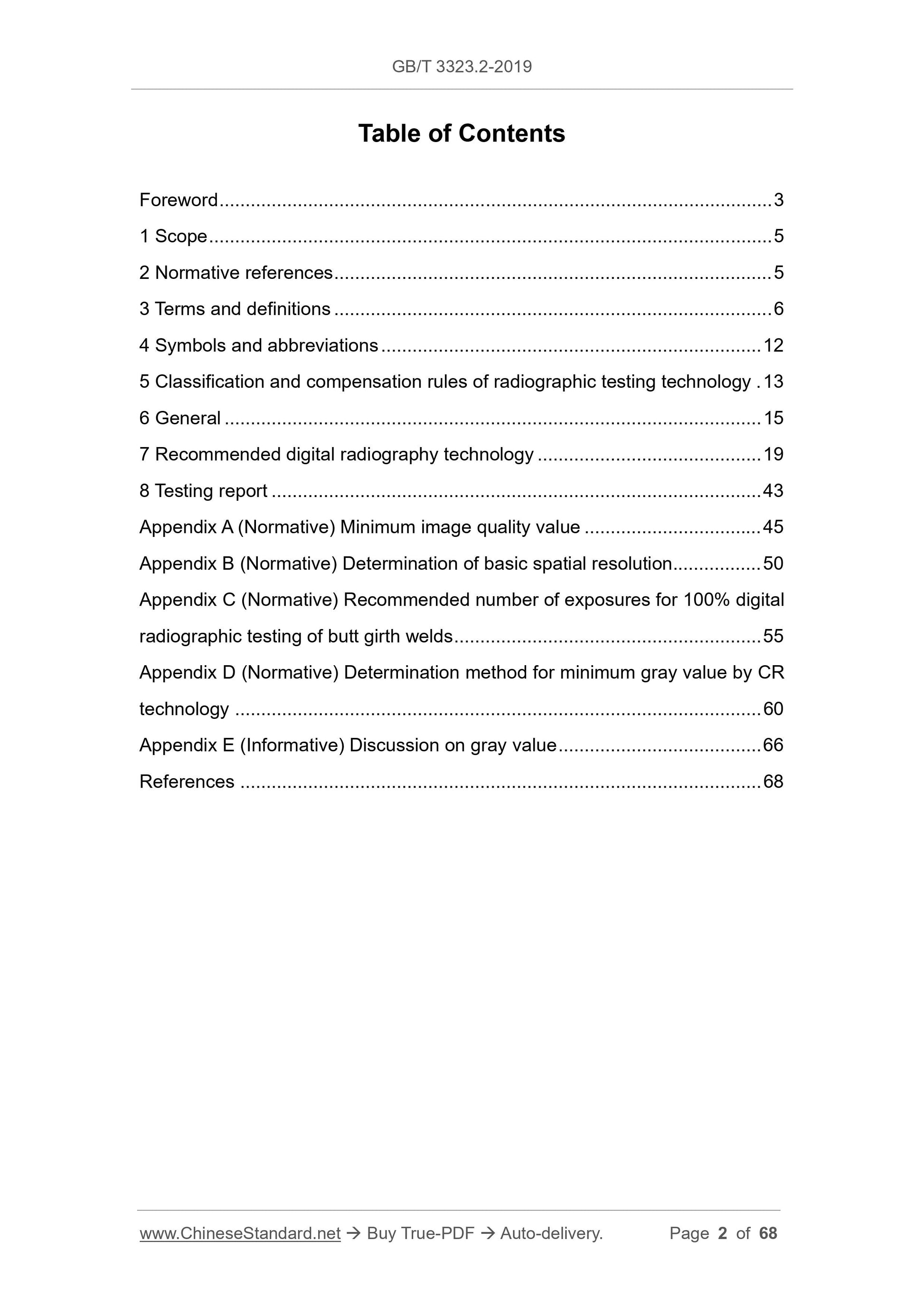
Table of Contents
Foreword ... 3
1 Scope ... 5
2 Normative references ... 5
3 Terms and definitions ... 6
4 Symbols and abbreviations ... 12
5 Classification and compensation rules of radiographic testing technology . 13
6 General ... 15
7 Recommended digital radiography technology ... 19
8 Testing report ... 43
Appendix A (Normative) Minimum image quality value ... 45
Appendix B (Normative) Determination of basic spatial resolution ... 50
Appendix C (Normative) Recommended number of exposures for 100% digital
radiographic testing of butt girth welds ... 55
Appendix D (Normative) Determination method for minimum gray value by CR
technology ... 60
Appendix E (Informative) Discussion on gray value ... 66
References ... 68
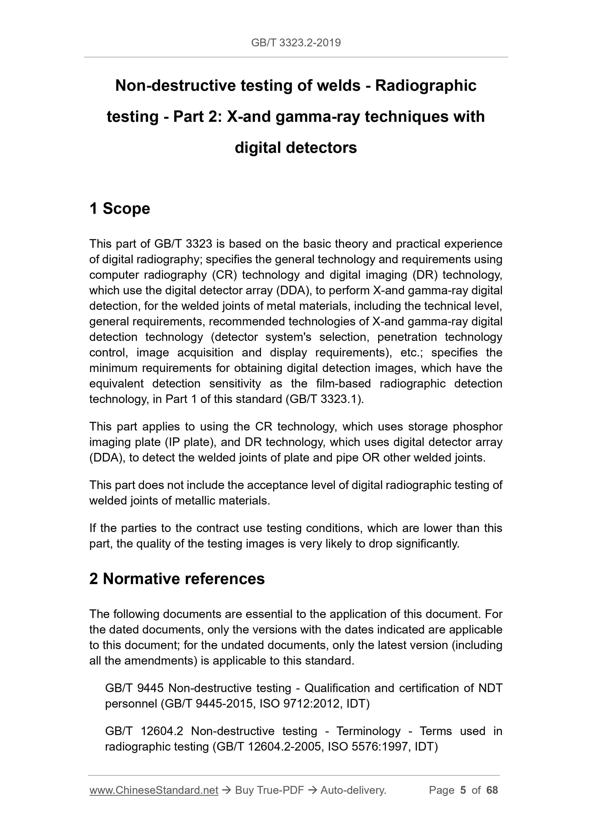
Non-destructive testing of welds - Radiographic
testing - Part 2: X-and gamma-ray techniques with
digital detectors
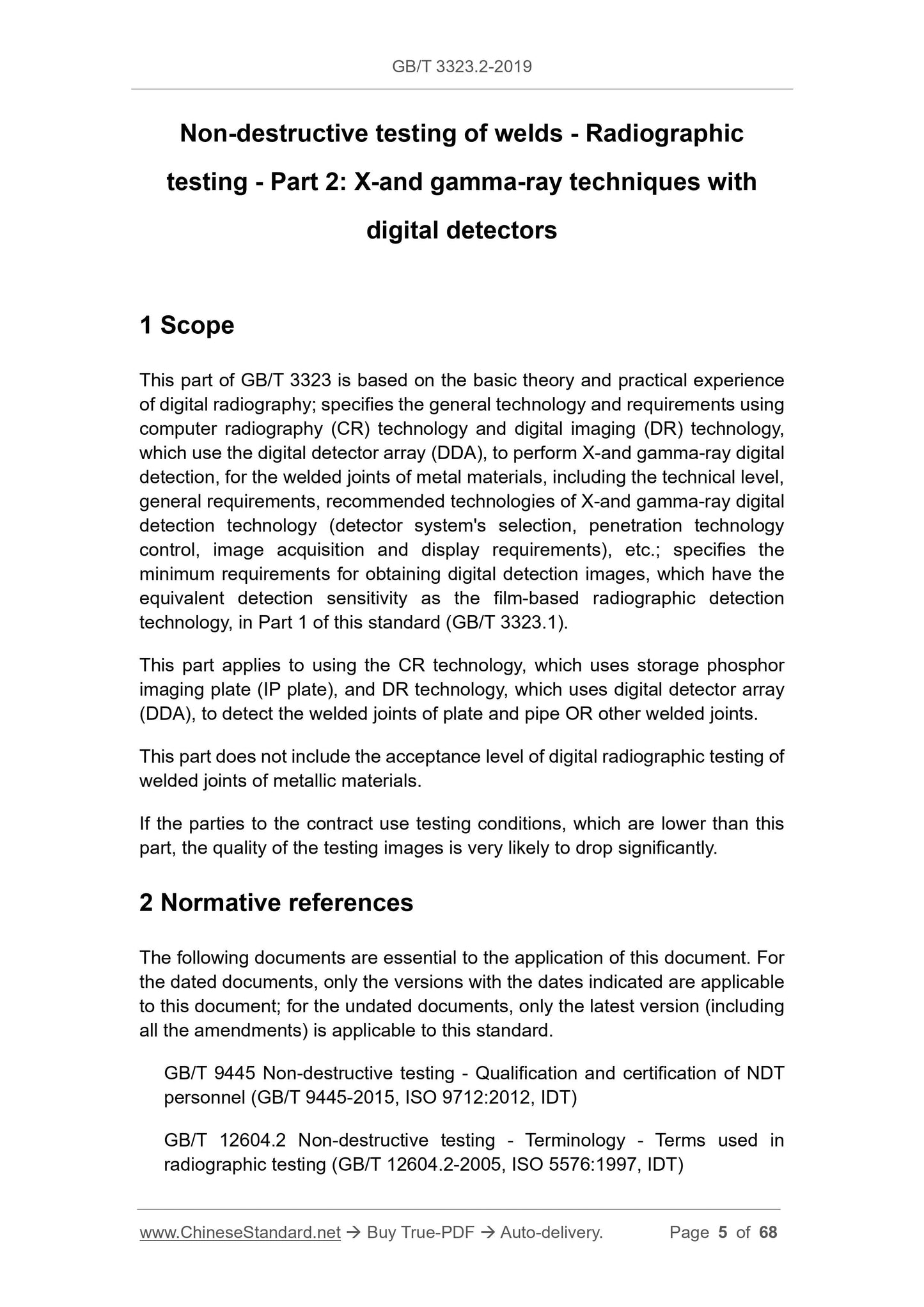
1 Scope
This part of GB/T 3323 is based on the basic theory and practical experience
of digital radiography; specifies the general technology and requirements using
computer radiography (CR) technology and digital imaging (DR) technology,
which use the digital detector array (DDA), to perform X-and gamma-ray digital
detection, for the welded joints of metal materials, including the technical level,
general requirements, recommended technologies of X-and gamma-ray digital
detection technology (detector system's selection, penetration technology
control, image acquisition and display requirements), etc.; specifies the
minimum requirements for obtaining digital detection images, which have the
equivalent detection sensitivity as the film-based radiographic detection
technology, in Part 1 of this standard (GB/T 3323.1).
This part applies to using the CR technology, which uses storage phosphor
imaging plate (IP plate), and DR technology, which uses digital detector array
(DDA), to detect the welded joints of plate and pipe OR other welded joints.
This part does not include the acceptance level of digital radiographic testing of
welded joints of metallic materials.
If the parties to the contract use testing conditions, which are lower than this
part, the quality of the testing images is very likely to drop significantly.
2 Normative references
The following documents are essential to the application of this document. For
the dated documents, only the versions with the dates indicated are applicable
to this document; for the undated documents, only the latest version (including
all the amendments) is applicable to this standard.
GB/T 9445 Non-destructive testing - Qualification and certification of NDT
personnel (GB/T 9445-2015, ISO 9712:2012, IDT)
GB/T 12604.2 Non-destructive testing - Terminology - Terms used in
radiographic testing (GB/T 12604.2-2005, ISO 5576:1997, IDT)
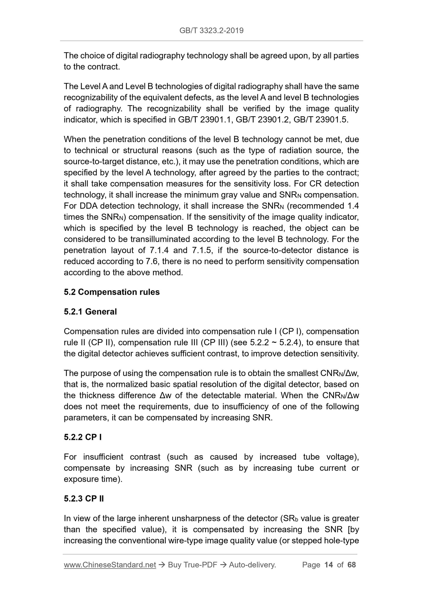
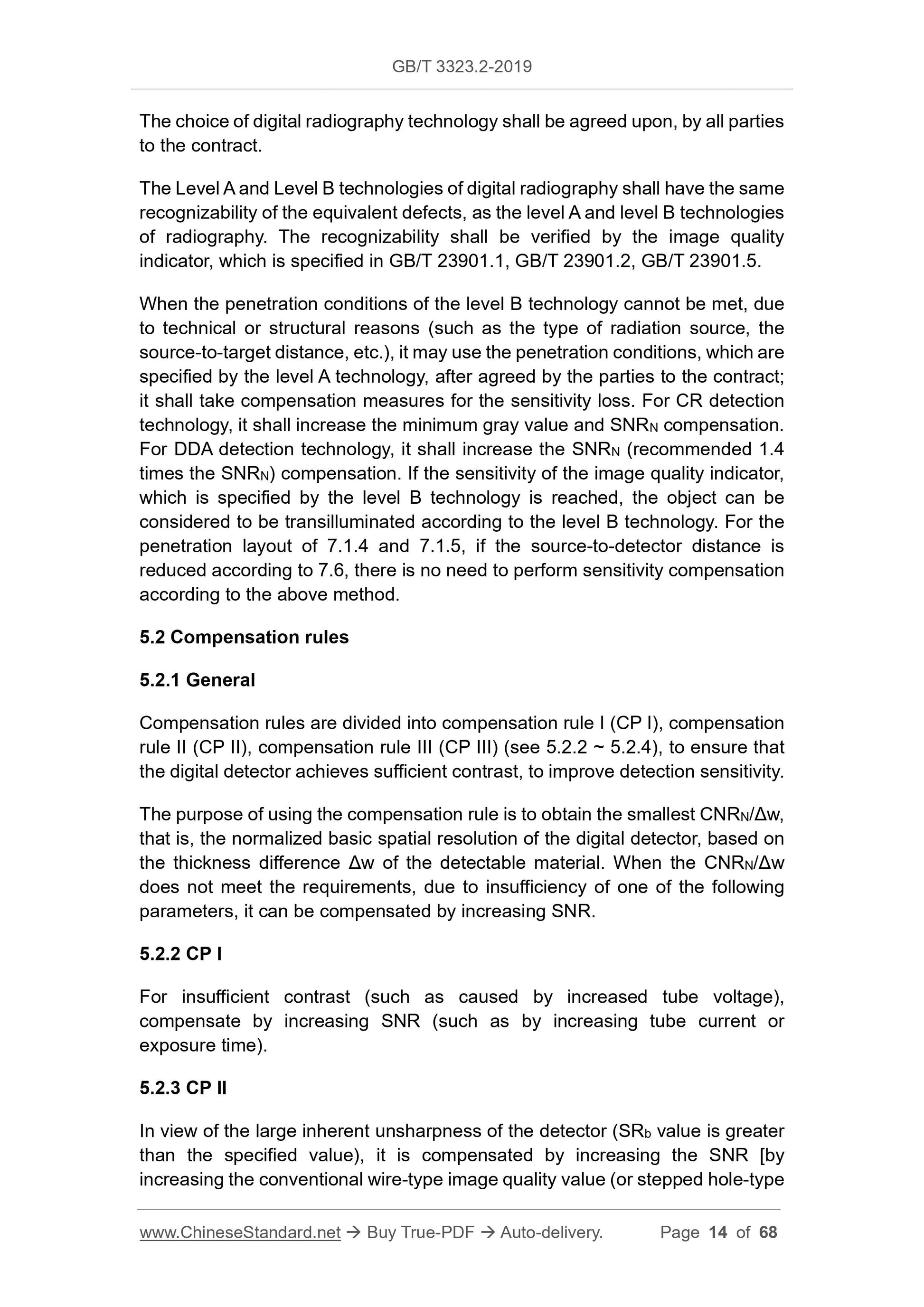
The choice of digital radiography technology shall be agreed upon, by all parties
to the contract.
The Level A and Level B technologies of digital radiography shall have the same
recognizability of the equivalent defects, as the level A and level B technologies
of radiography. The recognizability shall be verified by the image quality
indicator, which is specified in GB/T 23901.1, GB/T 23901.2, GB/T 23901.5.
When the penetration conditions of the level B technology cannot be met, due
to technical or structural reasons (such as the type of radiation source, the
source-to-target distance, etc.), it may use the penetration conditions, which are
specified by the level A technology, after agreed by the parties to the contract;
it shall take compensation measures for the sensitivity loss. For CR detection
technology, it shall increase the minimum gray value and SNRN compensation.
For DDA detection technology, it shall increase the SNRN (recommended 1.4
times the SNRN) compensation. If the sensitivity of the image quality indicator,
which is specified by the level B technology is reached, the object can be
considered to be transilluminated according to the level B technology. For the
penetration layout of 7.1.4 and 7.1.5, if the source-to-detector distance is
reduced according to 7.6, there is no need to perform sensitivity compensation
according to the above method.
5.2 Compensation rules
5.2.1 General
Compensation rules are divided into compensation rule I (CP I), compensation
rule II (CP II), compensation rule III (CP III) (see 5.2.2 ~ 5.2.4), to ensure that
the digital detector achieves sufficient contrast, to improve detection sensitivity.
The purpose of using the compensation rule is to obtain the smallest CNRN/Δw,
that is, the normalized basic spatial resolution of the digital detector, based on
the thickness difference Δw of the detectable material. When the CNRN/Δw
does not meet the requirements, due to insufficiency of one of the following
parameters, it can be compensated by increasing SNR.
5.2.2 CP I
For insufficient contrast (such as caused by increased tube voltage),
compensate by increasing SNR (such as by increasing tube current or
exposure time).
5.2.3 CP II
In view of the large inherent unsharpness of the detector (SRb value is greater
than the specified value), it is compensated by increasing the SNR [by
increasing the conventional wire-type image quality value (or stepped hole-type
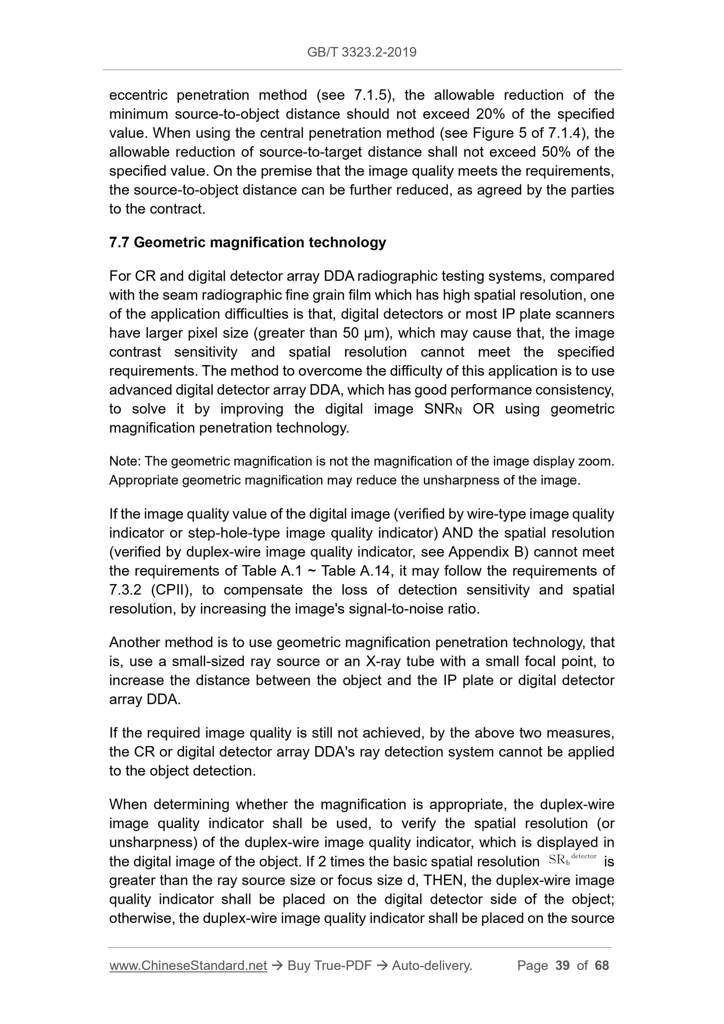
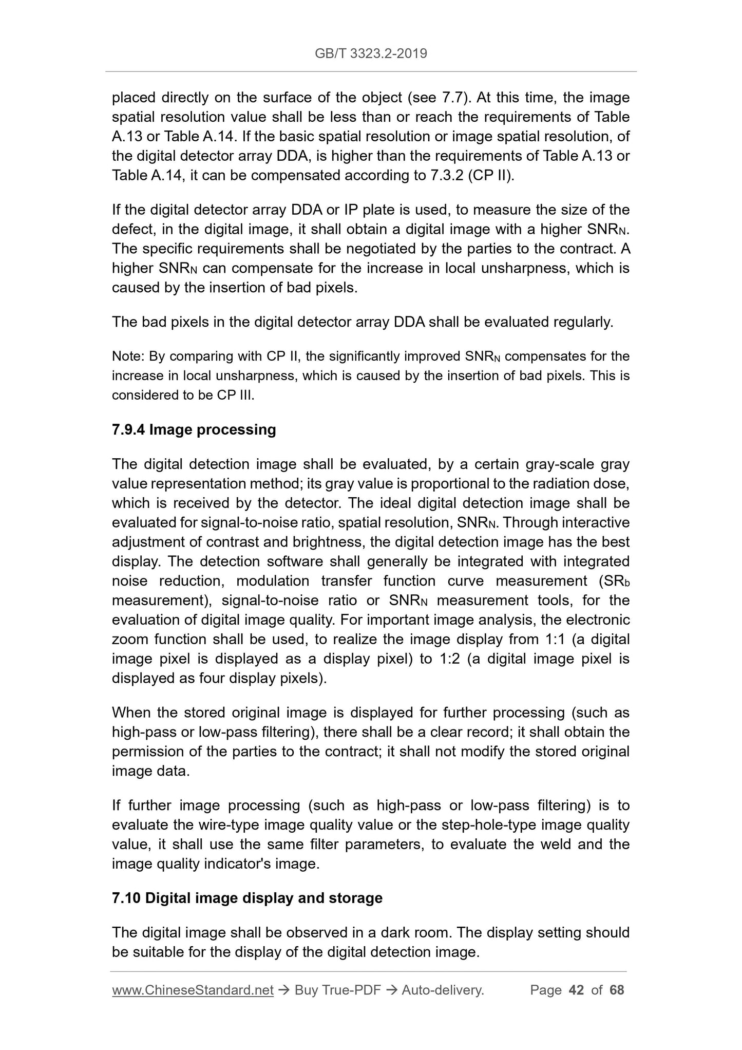
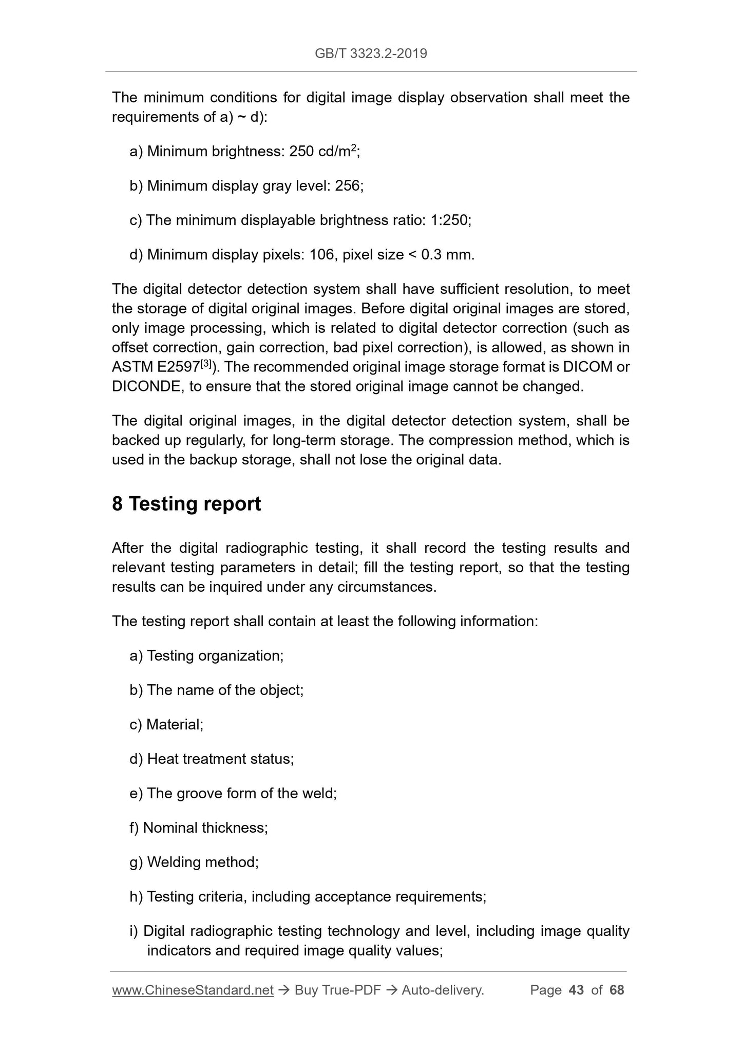
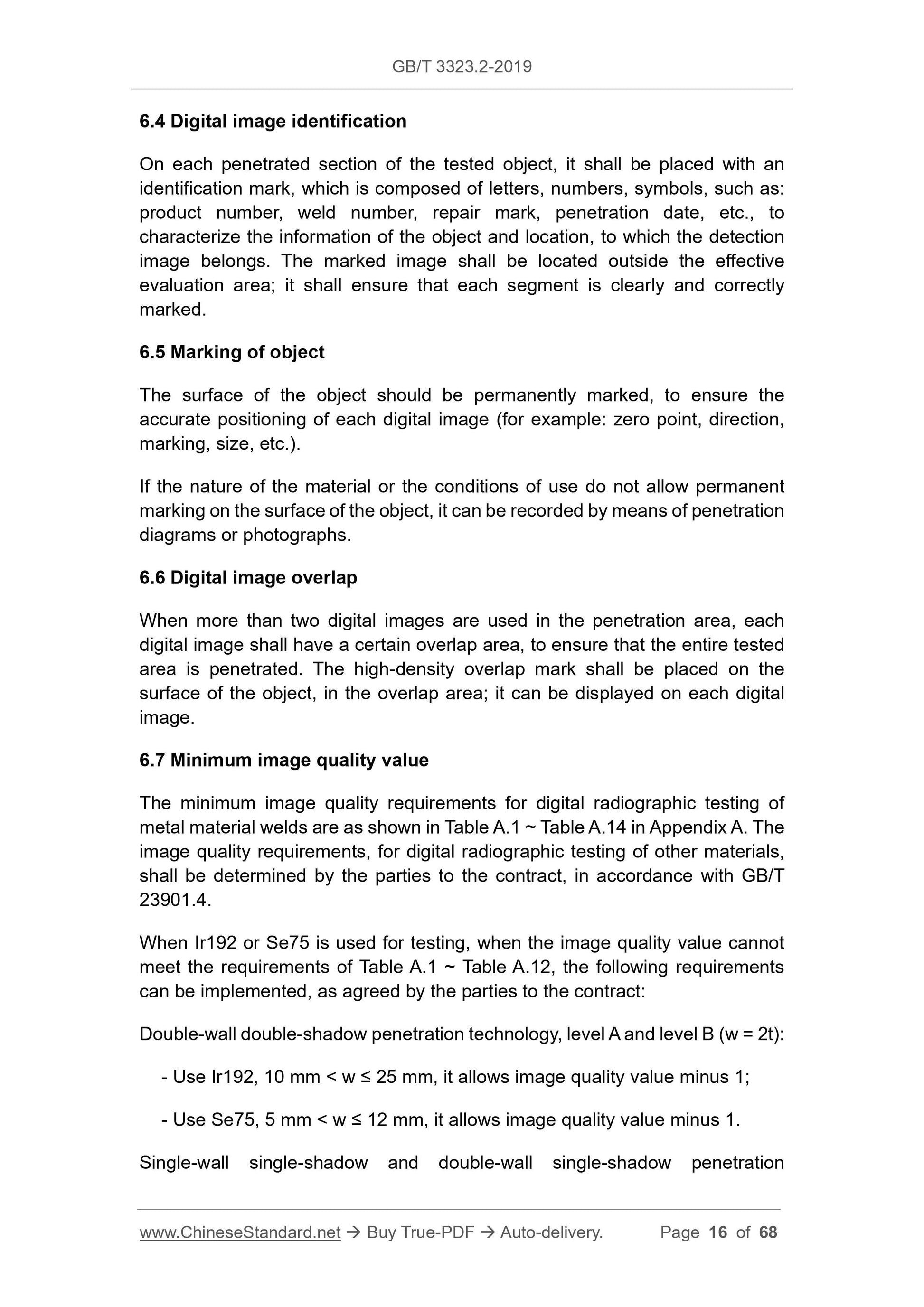
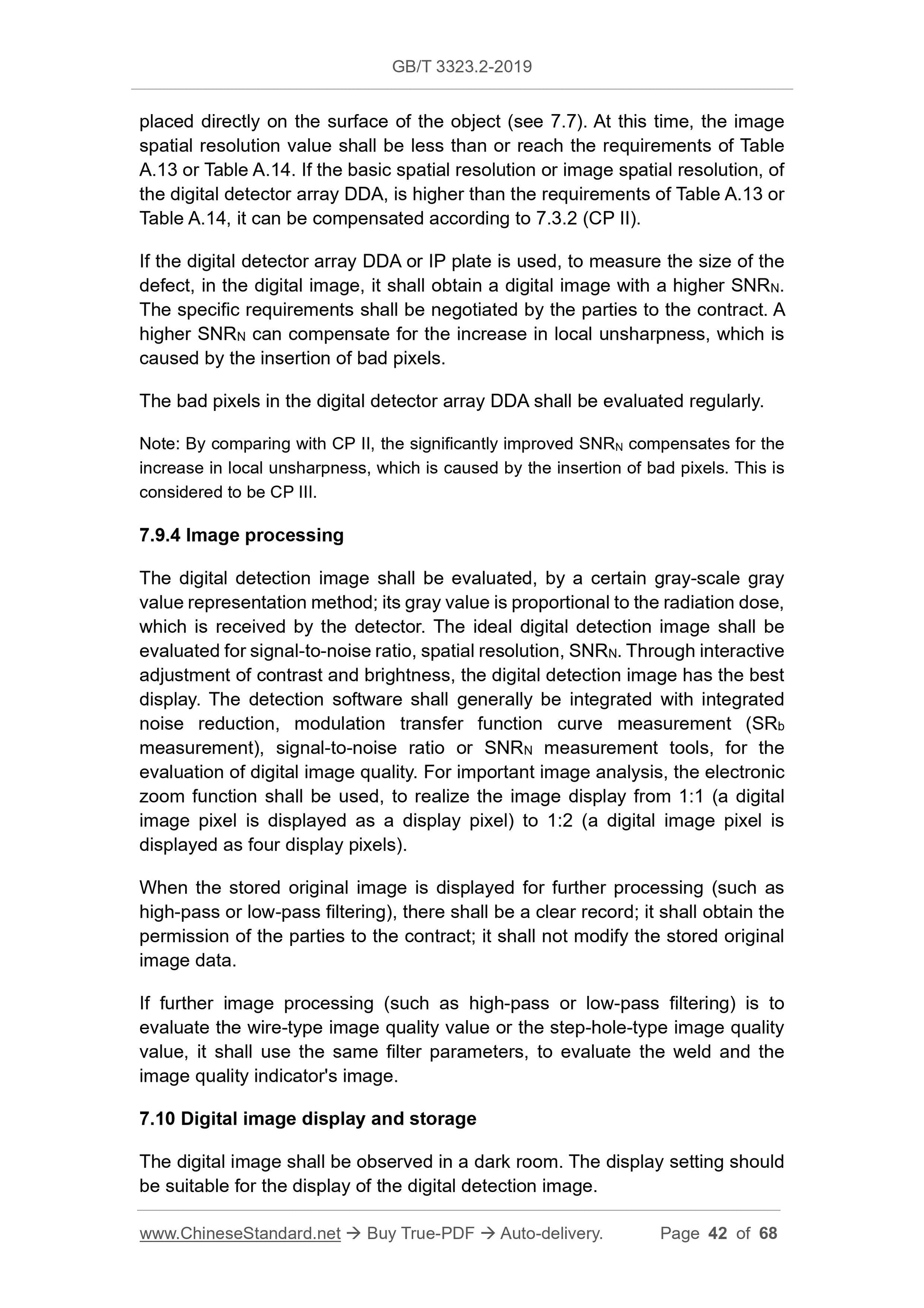
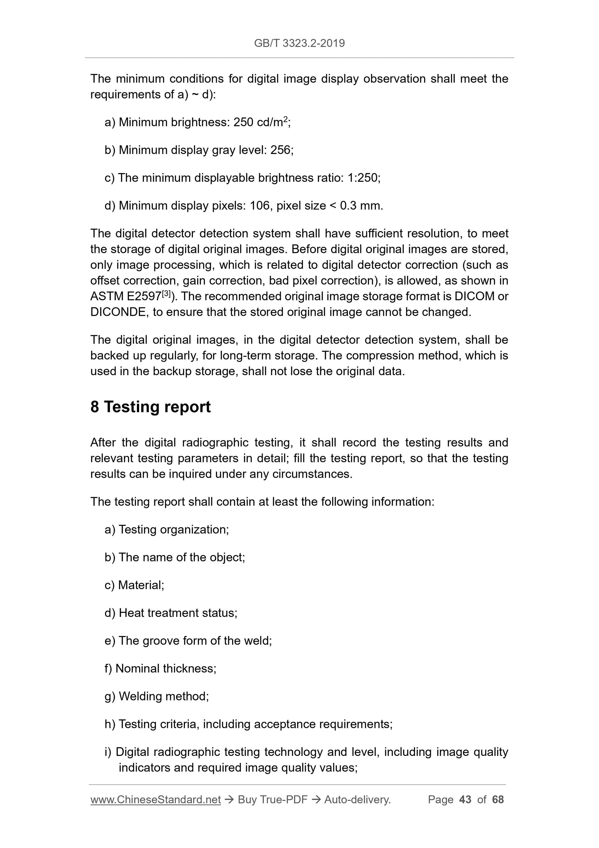
6.4 Digital image identification
On each penetrated section of the tested object, it shall be placed with an
identification mark, which is composed of letters, numbers, symbols, such as:
product number, weld number, repair mark, penetration date, etc., to
characterize the information of the object and location, to which the detection
image belongs. The marked image shall be located outside the effective
evaluation area; it shall ensure that each segment is clearly and correctly
marked.
6.5 Marking of object
The surface of the object should be permanently marked, to ensure the
accurate positioning of each digital image (for example: zero point, direction,
marking, size, etc.).
If the nature of the material or the conditions of use do not allow permanent
marking on the surface of the object, it can be recorded by means of penetration
diagrams or photographs.
6.6 Digital image overlap
When more than two digital images are used in the penetration area, each
digital image shall have a certain overlap area, to ensure that the entire tested
area is penetrated. The high-density overlap mark shall be placed on the
surface of the object, in the overlap area; it can be displayed on each digital
image.
6.7 Minimum image quality value
The minimum image quality requirements for digital radiographic testing of
metal material welds are as shown in Table A.1 ~ Table A.14 in Appendix A. The
image quality requirements, for digital radiographic testing of other materials,
shall be determined by the parties to the contract, in accordance with GB/T
23901.4.
When Ir192 or Se75 is used for testing, when the image quality value cannot
meet the requirements of Table A.1 ~ Table A.12, the following requirements
can be implemented, as agreed by the parties to the contrac...