www.ChineseStandard.us -- Field Test Asia Pte. Ltd.
GB/T 33145-2023: Large capacity seamless steel gas cylinders
Delivery: 9 seconds. Download (and Email) true-PDF + Invoice.
Get Quotation: Click
GB/T 33145-2023 (Self-service in 1-minute)
Newer / historical versions: GB/T 33145-2023Preview True-PDF
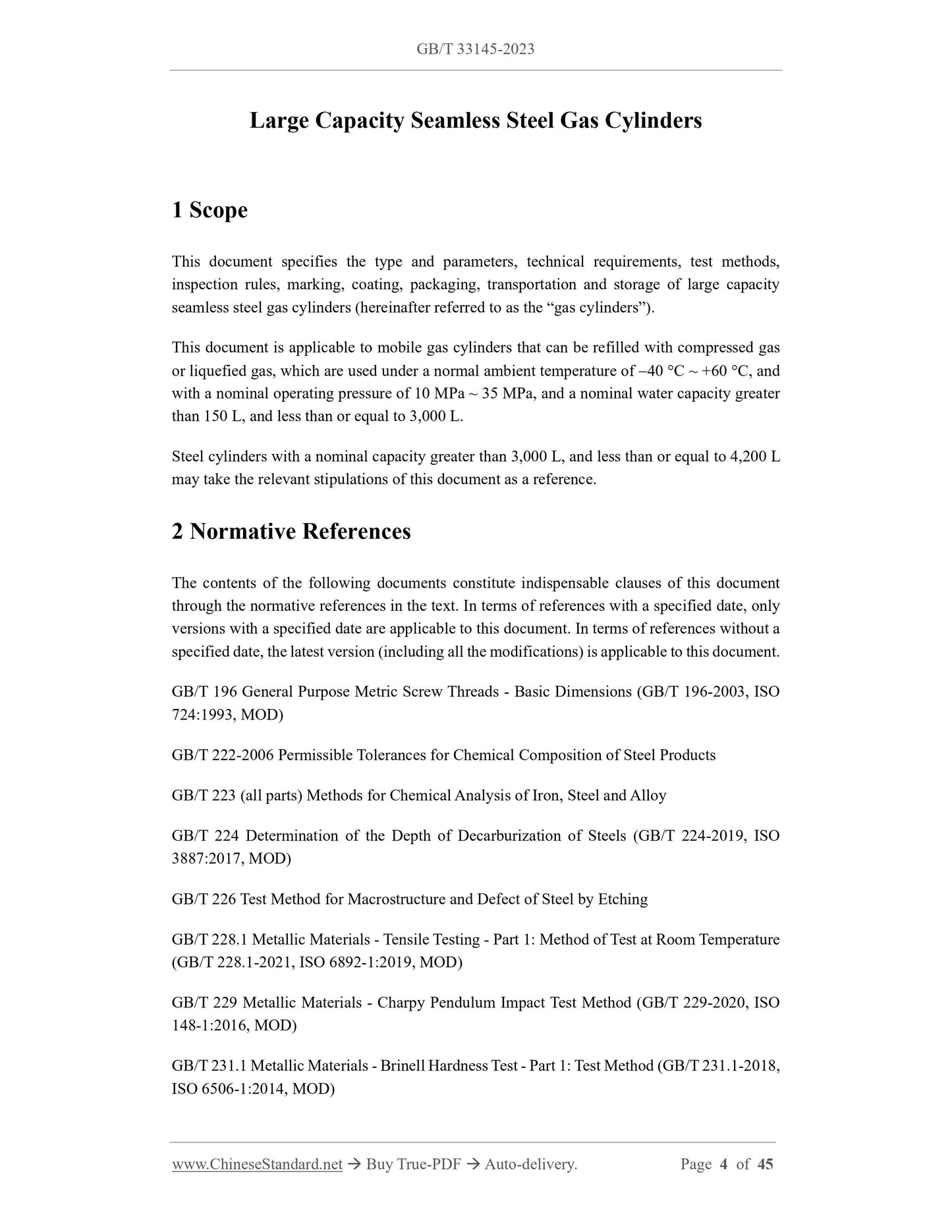
Scope
This document specifies the type and parameters, technical requirements, test methods,
inspection rules, marking, coating, packaging, transportation and storage of large capacity
seamless steel gas cylinders (hereinafter referred to as the “gas cylinders”).
This document is applicable to mobile gas cylinders that can be refilled with compressed gas
or liquefied gas, which are used under a normal ambient temperature of 40 C ~ +60 C, and
with a nominal operating pressure of 10 MPa ~ 35 MPa, and a nominal water capacity greater
than 150 L, and less than or equal to 3,000 L.
Steel cylinders with a nominal capacity greater than 3,000 L, and less than or equal to 4,200 L
may take the relevant stipulations of this document as a reference.
Basic Data
| Standard ID | GB/T 33145-2023 (GB/T33145-2023) |
| Description (Translated English) | Large capacity seamless steel gas cylinders |
| Sector / Industry | National Standard (Recommended) |
| Classification of Chinese Standard | J74 |
| Classification of International Standard | 23.020.30 |
| Word Count Estimation | 34,380 |
| Date of Issue | 2023-05-23 |
| Date of Implementation | 2023-12-01 |
| Older Standard (superseded by this standard) | GB/T 33145-2016 |
| Issuing agency(ies) | State Administration for Market Regulation, China National Standardization Administration |