GB/T 33014.5-2016 English PDF (GBT33014.5-2016)
Regular price
$135.00 USD
Regular price
Sale price
$135.00 USD
Unit price
/
per
Delivery: 3 seconds. Download true-PDF + Invoice.
Get QUOTATION in 1-minute: Click GB/T 33014.5-2016
Historical versions: GB/T 33014.5-2016
Preview True-PDF (Reload/Scroll if blank)
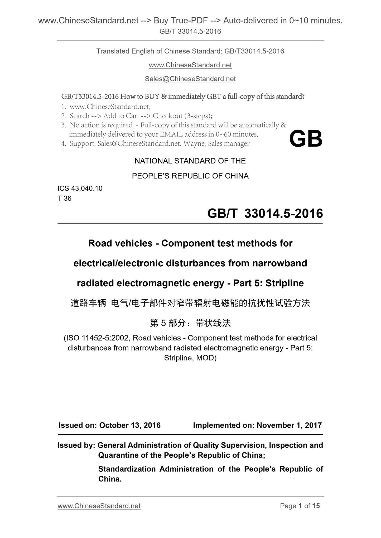
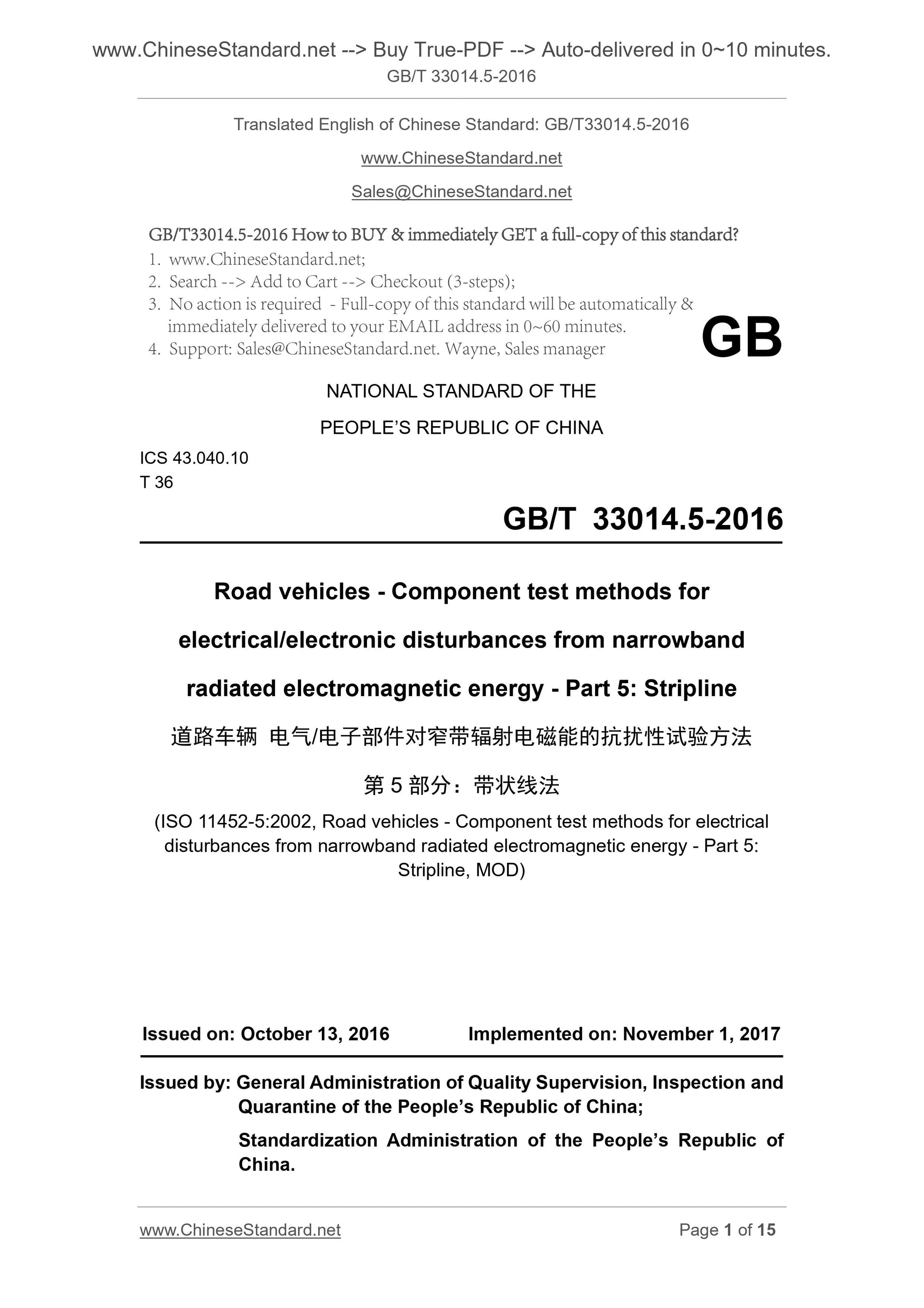
GB/T 33014.5-2016: Road vehicles -- Component test methods for electrical/electronic disturbances from narrowband radiated electromagnetic energy -- Part 5: Strip line
GB/T 33014.5-2016
GB
NATIONAL STANDARD OF THE
PEOPLE’S REPUBLIC OF CHINA
ICS 43.040.10
T 36
Road vehicles - Component test methods for
electrical/electronic disturbances from narrowband
radiated electromagnetic energy - Part 5. Stripline
(ISO 11452-5.2002, Road vehicles - Component test methods for electrical
disturbances from narrowband radiated electromagnetic energy - Part 5.
Stripline, MOD)
ISSUED ON. OCTOBER 13, 2016
IMPLEMENTED ON. NOVEMBER 1, 2017
Issued by. General Administration of Quality Supervision, Inspection and
Quarantine of the People’s Republic of China;
Standardization Administration of the People’s Republic of
China.
3. No action is required - Full-copy of this standard will be automatically and
immediately delivered to your EMAIL address in 0~60 minutes.
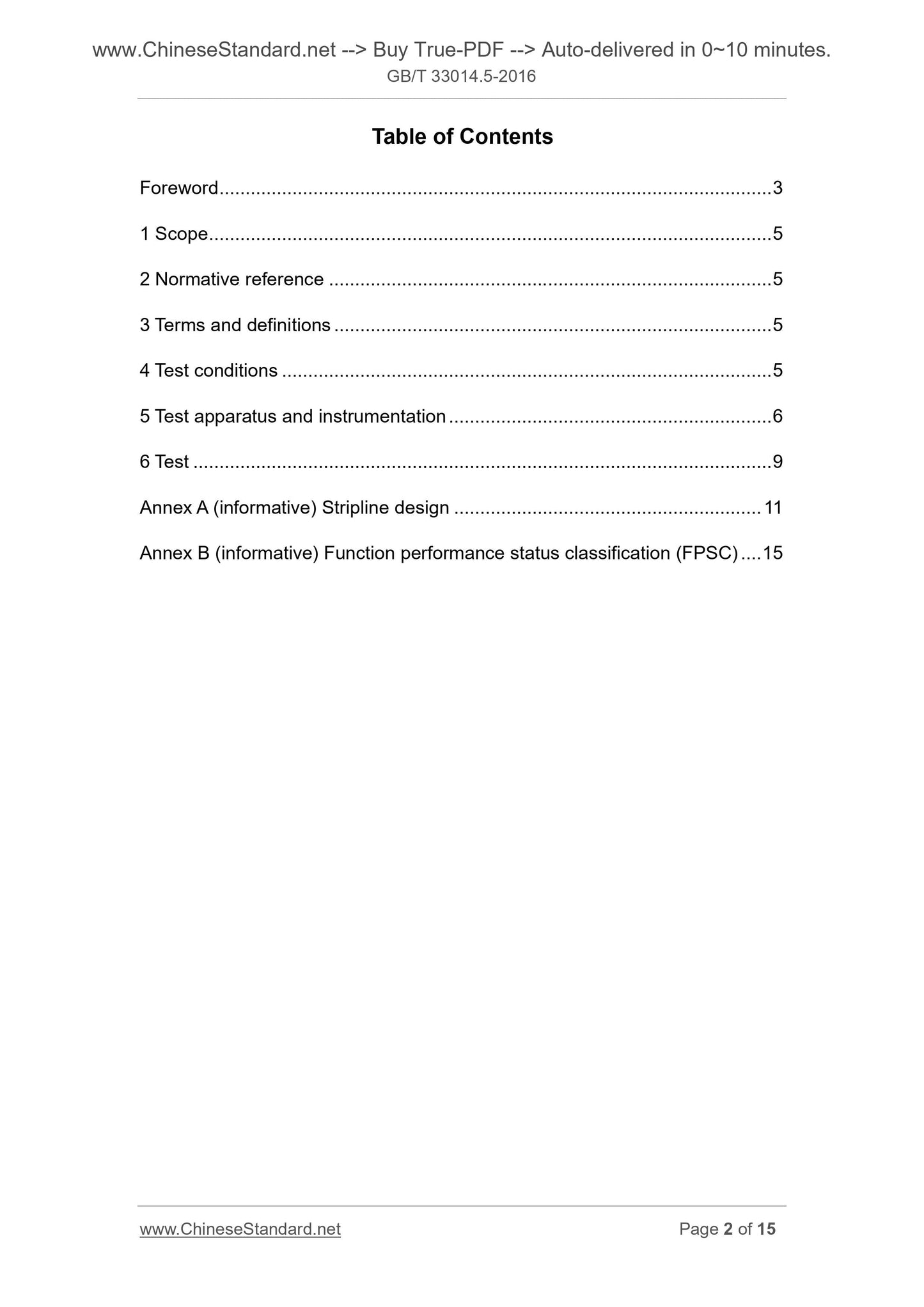
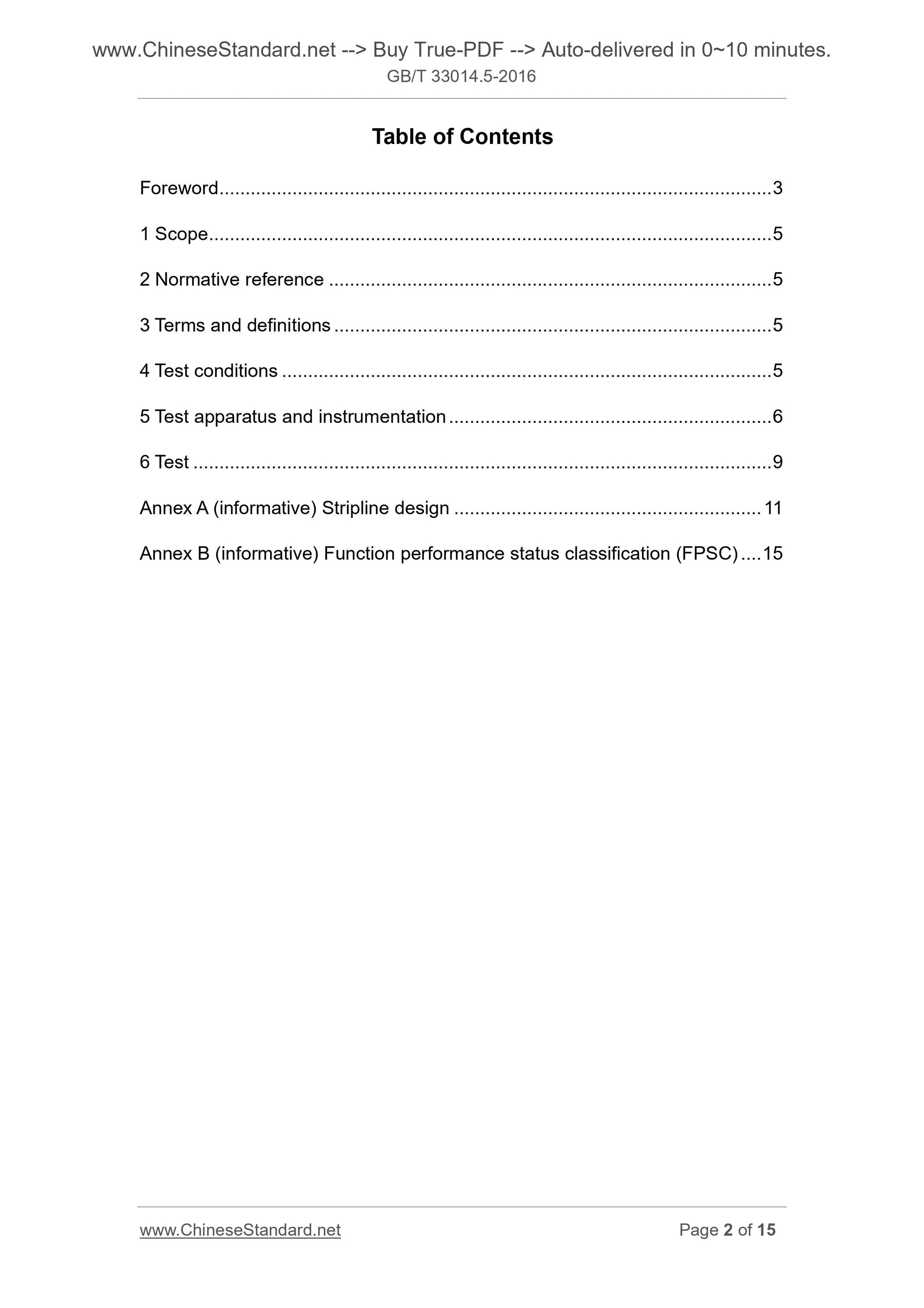
Table of Contents
Foreword ... 3
1 Scope ... 5
2 Normative reference ... 5
3 Terms and definitions ... 5
4 Test conditions ... 5
5 Test apparatus and instrumentation ... 6
6 Test ... 9
Annex A (informative) Stripline design ... 11
Annex B (informative) Function performance status classification (FPSC) ... 15
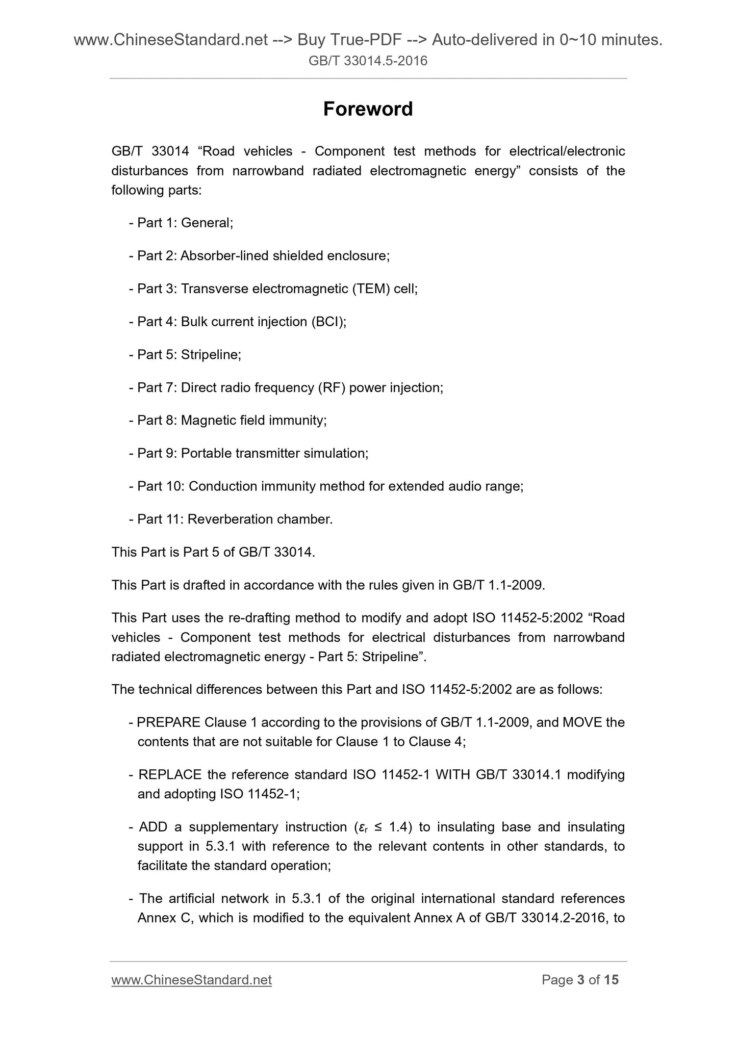
Foreword
GB/T 33014 “Road vehicles - Component test methods for electrical/electronic
disturbances from narrowband radiated electromagnetic energy” consists of the
following parts.
- Part 1. General;
- Part 2. Absorber-lined shielded enclosure;
- Part 3. Transverse electromagnetic (TEM) cell;
- Part 4. Bulk current injection (BCI);
- Part 5. Stripeline;
- Part 7. Direct radio frequency (RF) power injection;
- Part 8. Magnetic field immunity;
- Part 9. Portable transmitter simulation;
- Part 10. Conduction immunity method for extended audio range;
- Part 11. Reverberation chamber.
This Part is Part 5 of GB/T 33014.
This Part is drafted in accordance with the rules given in GB/T 1.1-2009.
This Part uses the re-drafting method to modify and adopt ISO 11452-5.2002 “Road
vehicles - Component test methods for electrical disturbances from narrowband
radiated electromagnetic energy - Part 5. Stripeline”.
The technical differences between this Part and ISO 11452-5.2002 are as follows.
- PREPARE Clause 1 according to the provisions of GB/T 1.1-2009, and MOVE the
contents that are not suitable for Clause 1 to Clause 4;
- REPLACE the reference standard ISO 11452-1 WITH GB/T 33014.1 modifying
and adopting ISO 11452-1;
- ADD a supplementary instruction (εr ≤ 1.4) to insulating base and insulating
support in 5.3.1 with reference to the relevant contents in other standards, to
facilitate the standard operation;
- The artificial network in 5.3.1 of the original international standard references
Annex C, which is modified to the equivalent Annex A of GB/T 33014.2-2016, to
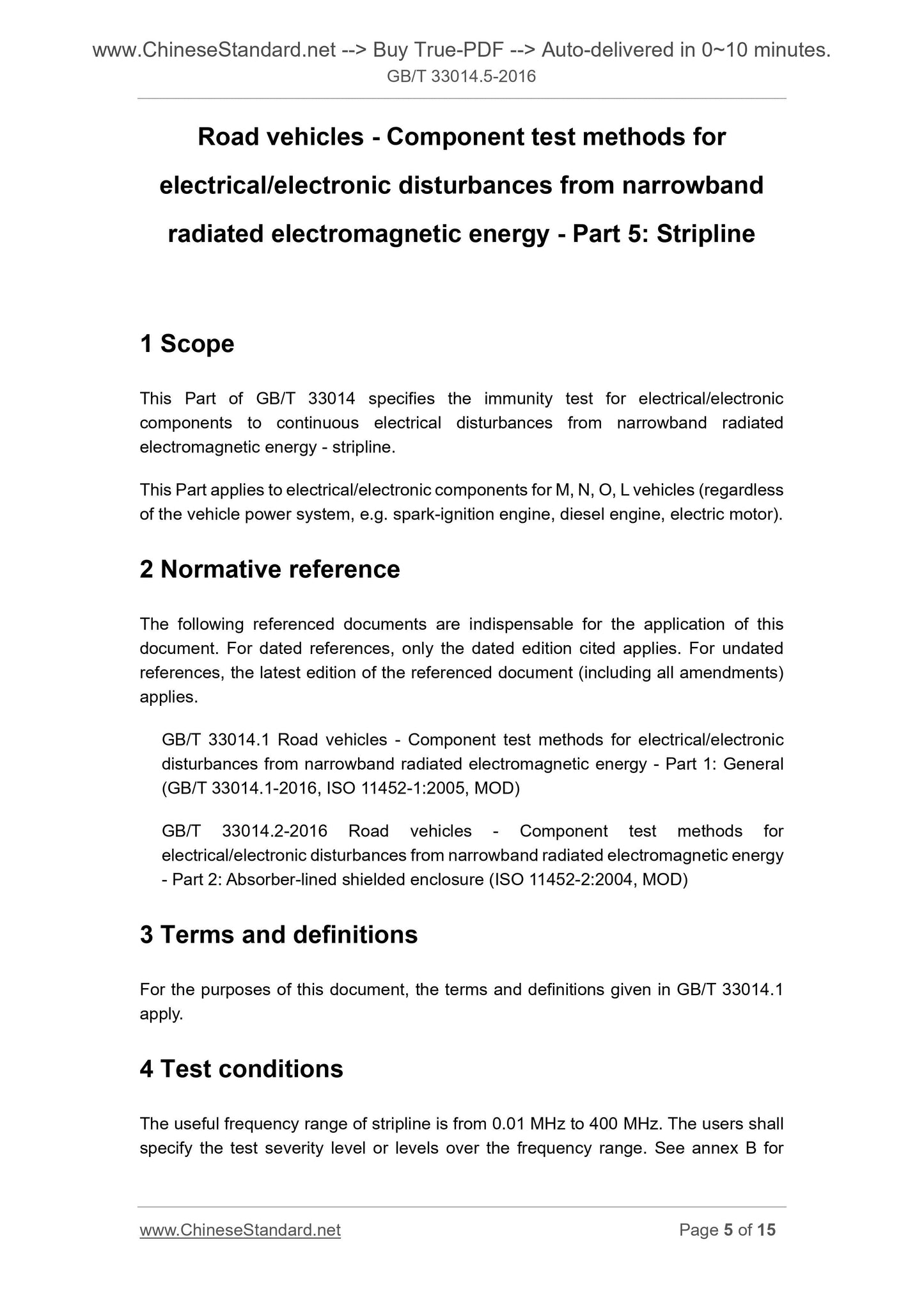
Road vehicles - Component test methods for
electrical/electronic disturbances from narrowband
radiated electromagnetic energy - Part 5. Stripline
1 Scope
This Part of GB/T 33014 specifies the immunity test for electrical/electronic
components to continuous electrical disturbances from narrowband radiated
electromagnetic energy - stripline.
This Part applies to electrical/electronic components for M, N, O, L vehicles (regardless
of the vehicle power system, e.g. spark-ignition engine, diesel engine, electric motor).
2 Normative reference
The following referenced documents are indispensable for the application of this
document. For dated references, only the dated edition cited applies. For undated
references, the latest edition of the referenced document (including all amendments)
applies.
GB/T 33014.1 Road vehicles - Component test methods for electrical/electronic
disturbances from narrowband radiated electromagnetic energy - Part 1. General
(GB/T 33014.1-2016, ISO 11452-1.2005, MOD)
GB/T 33014.2-2016 Road vehicles - Component test methods for
electrical/electronic disturbances from narrowband radiated electromagnetic energy
- Part 2. Absorber-lined shielded enclosure (ISO 11452-2.2004, MOD)
3 Terms and definitions
For the purposes of this document, the terms and definitions given in GB/T 33014.1
apply.
4 Test conditions
The useful frequency range of stripline is from 0.01 MHz to 400 MHz. The users shall
specify the test severity level or levels over the frequency range. See annex B for
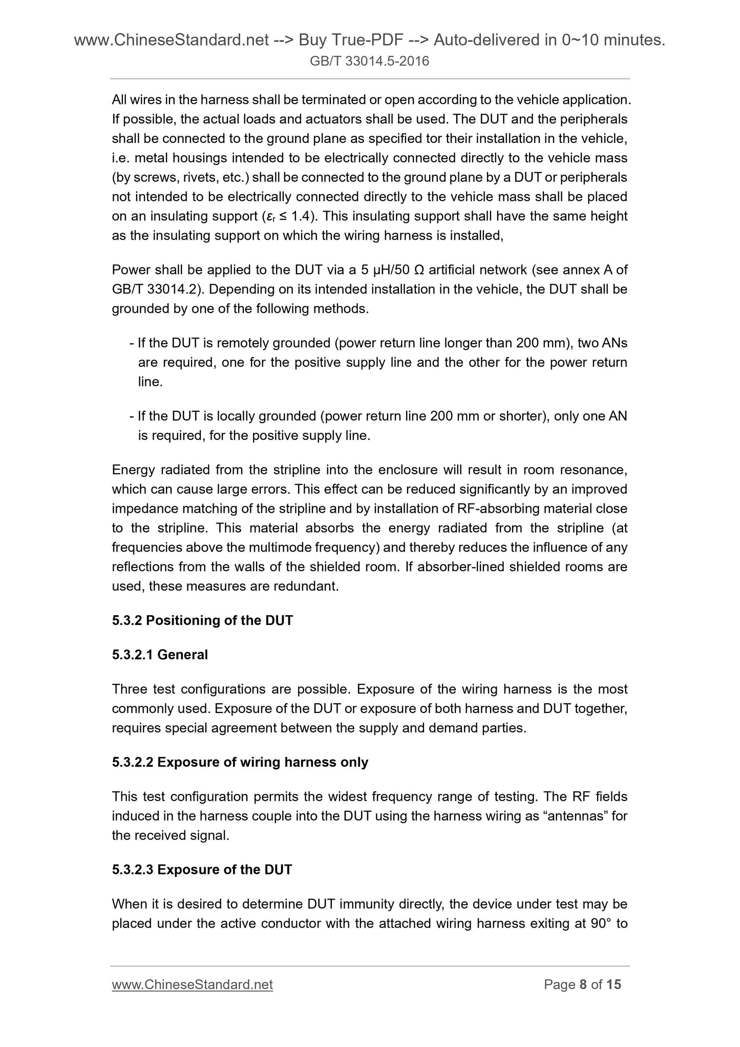
All wires in the harness shall be terminated or open according to the vehicle application.
If possible, the actual loads and actuators shall be used. The DUT and the peripherals
shall be connected to the ground plane as specified tor their installation in the vehicle,
i.e. metal housings intended to be electrically connected directly to the vehicle mass
(by screws, rivets, etc.) shall be connected to the ground plane by a DUT or peripherals
not intended to be electrically connected directly to the vehicle mass shall be placed
on an insulating support (εr ≤ 1.4). This insulating support shall have the same height
as the insulating support on which the wiring harness is installed,
Power shall be applied to the DUT via a 5 μH/50 Ω artificial network (see annex A of
GB/T 33014.2). Depending on its intended installation in the vehicle, the DUT shall be
grounded by one of the following methods.
- If the DUT is remotely grounded (power return line longer than 200 mm), two ANs
are required, one for the positive supply line and the other for the power return
line.
- If the DUT is locally grounded (power return line 200 mm or shorter), only one AN
is required, for the positive supply line.
Energy radiated from the stripline into the enclosure will result in room resonance,
which can cause large errors. This effect can be reduced significantly by an improved
impedance matching of the stripline and by installation of RF-absorbing material close
to the stripline. This material absorbs the energy radiated from the stripline (at
frequencies above the multimode frequency) and thereby reduces the influence of any
reflections from the walls of the shielded room. If absorber-lined shielded rooms are
used, these measures are redundant.
5.3.2 Positioning of the DUT
5.3.2.1 General
Three test configurations are possible. Exposure of the wiring harness is the most
commonly used. Exposure of the DUT or exposure of both harness and DUT together,
requires special agreement between the supply and demand parties.
5.3.2.2 Exposure of wiring harness only
This test configuration permits the widest frequency range of testing. The RF fields
induced in the harness couple into the DUT using the harness wiring as “antennas” for
the received signal.
5.3.2.3 Exposure of the DUT
When it is desired to determine DUT immunity directly, the device under test may be
placed under the active conductor with the attached wiring harness exiting at 90° to
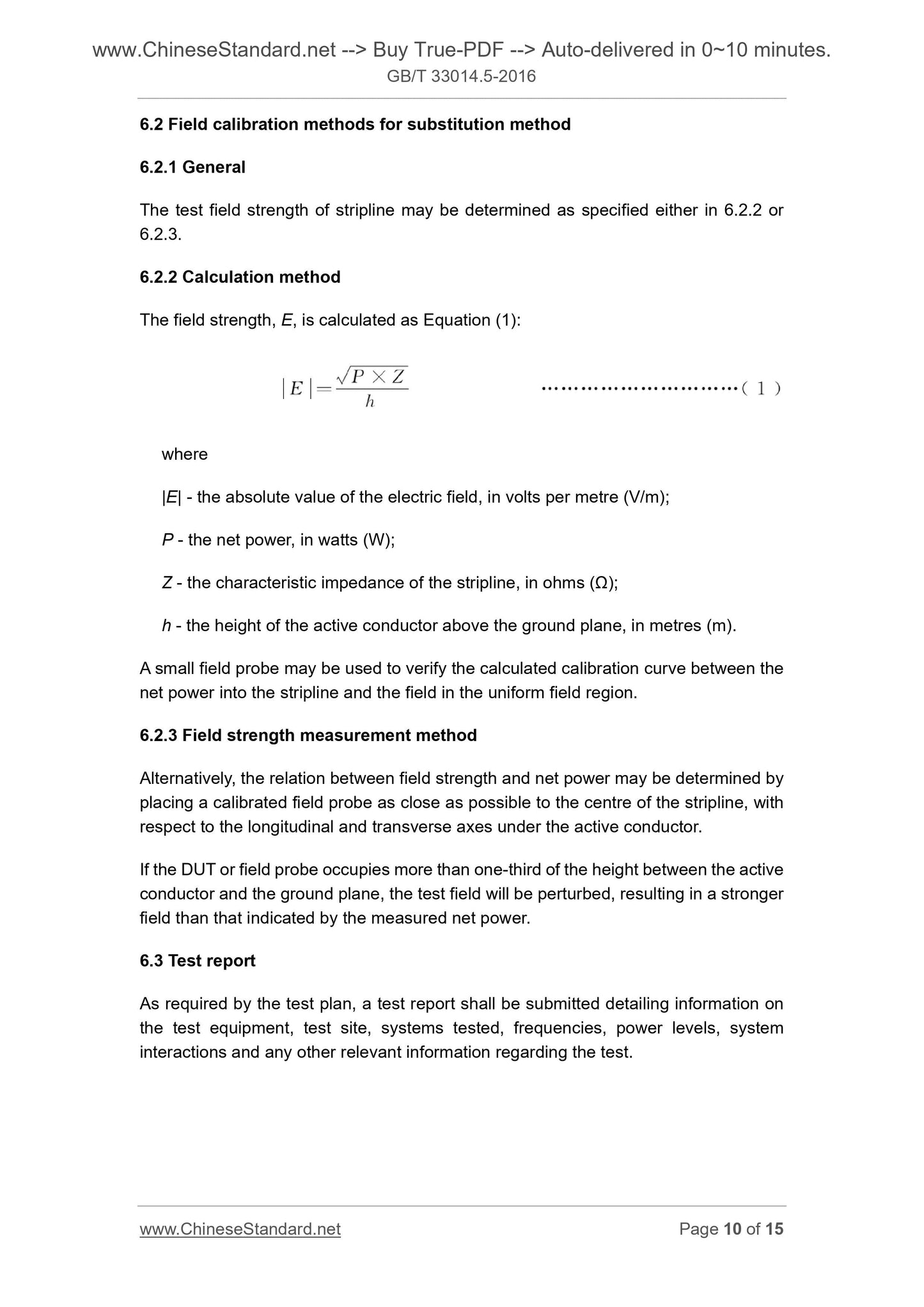
6.2 Field calibration methods for substitution method
6.2.1 General
The test field strength of stripline may be determined as specified either in 6.2.2 or
6.2.3.
6.2.2 Calculation method
The field strength, E, is calculated as Equation (1).
where
|E| - the absolute value of the electric field, in volts per metre (V/m);
P - the net power, in watts (W);
Z - the characteristic impedance of the stripline, in ohms (Ω);
h - the height of the active conductor above the ground plane, in metres (m).
A small field probe may be used to verify the calculated calibration curve between the
net power into the stripline and the field in the uniform field region.
6.2.3 Field strength measurement method