1
/
of
6
www.ChineseStandard.us -- Field Test Asia Pte. Ltd.
GB/T 33014.2-2016 English PDF (GB/T33014.2-2016)
GB/T 33014.2-2016 English PDF (GB/T33014.2-2016)
Regular price
$125.00
Regular price
Sale price
$125.00
Unit price
/
per
Shipping calculated at checkout.
Couldn't load pickup availability
GB/T 33014.2-2016: Road vehicles -- Component test methods for electrical/electronic disturbances from narrowband radiated electromagnetic energy -- Part 2: Absorber-lined shielded enclosure
Delivery: 9 seconds. Download (and Email) true-PDF + Invoice.Get Quotation: Click GB/T 33014.2-2016 (Self-service in 1-minute)
Newer / historical versions: GB/T 33014.2-2016
Preview True-PDF
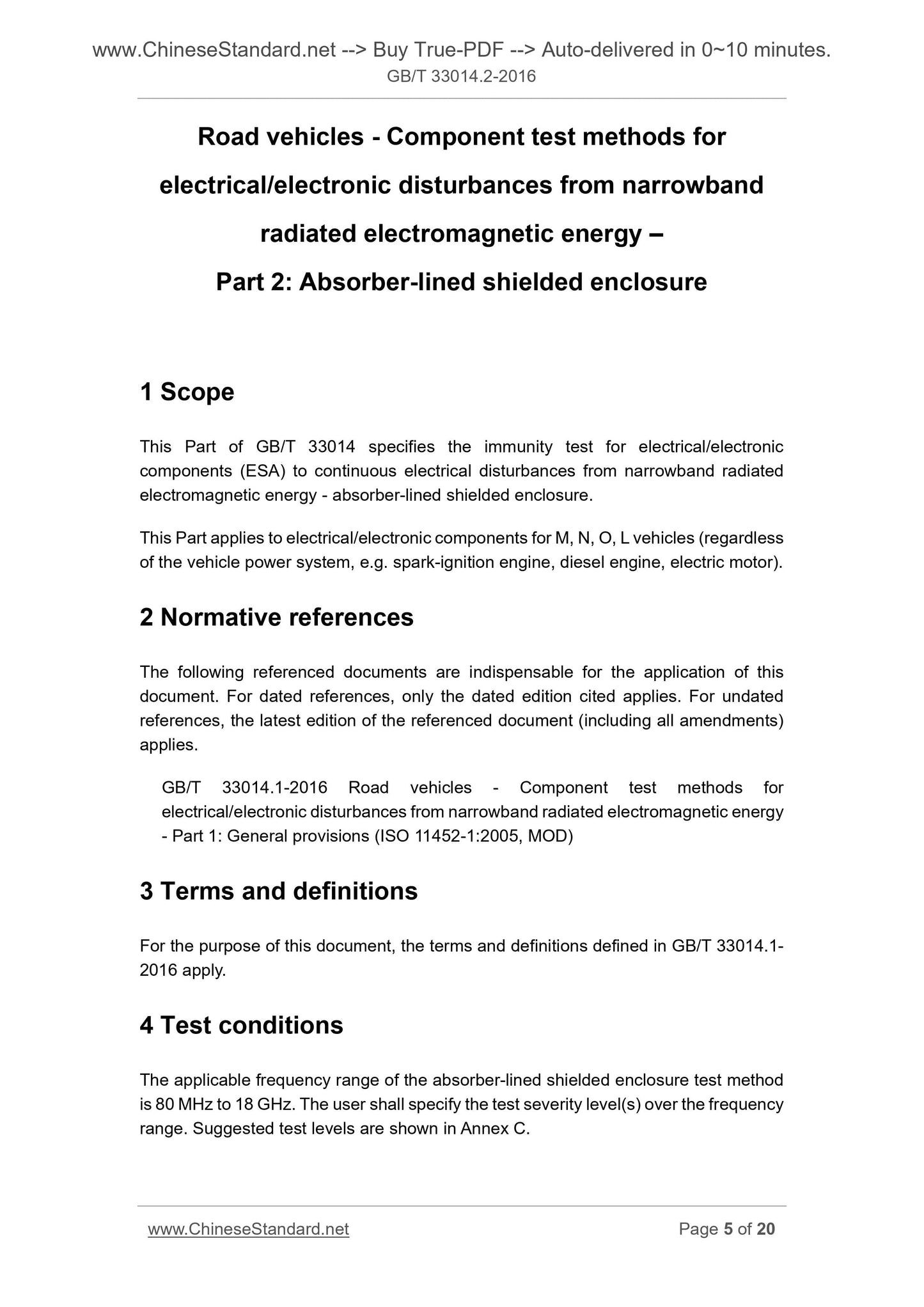
Scope
This Part of GB/T 33014 specifies the immunity test for electrical/electroniccomponents (ESA) to continuous electrical disturbances from narrowband radiated
electromagnetic energy - absorber-lined shielded enclosure.
Basic Data
| Standard ID | GB/T 33014.2-2016 (GB/T33014.2-2016) |
| Description (Translated English) | Road vehicles -- Component test methods for electrical/electronic disturbances from narrowband radiated electromagnetic energy -- Part 2: Absorber-lined shielded enclosure |
| Sector / Industry | National Standard (Recommended) |
| Classification of Chinese Standard | T36 |
| Classification of International Standard | 43.040.10 |
| Word Count Estimation | 18,178 |
| Date of Issue | 2016-10-13 |
| Date of Implementation | 2017-11-01 |
| Regulation (derived from) | National Standard Notice No.1716 of 2016 |
| Issuing agency(ies) | General Administration of Quality Supervision, Inspection and Quarantine of the People's Republic of China, Standardization Administration of the People's Republic of China |
Share