Skip to product information
1 of 12

PayPal, credit cards. Download editable-PDF & invoice in 1 second!

GB/T 32896-2016 English PDF (GBT32896-2016)

GB/T 32896-2016 English PDF (GBT32896-2016)

Regular price $150.00 USD
Regular price Sale price $150.00 USD
Sale Sold out
Shipping calculated at checkout.
Delivery: 3 seconds. Download true-PDF + Invoice.
Get QUOTATION in 1-minute: Click GB/T 32896-2016
Historical versions: GB/T 32896-2016
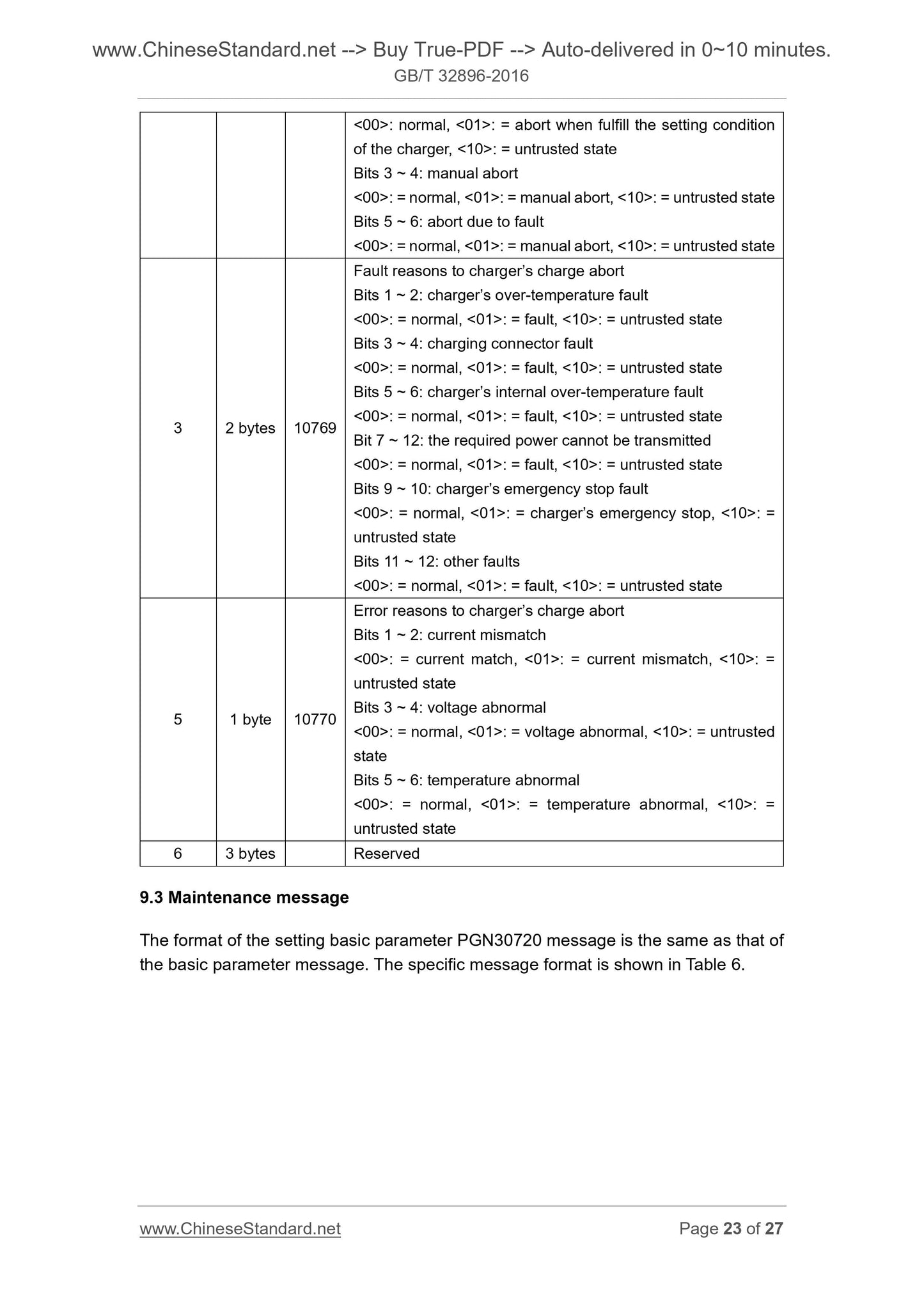
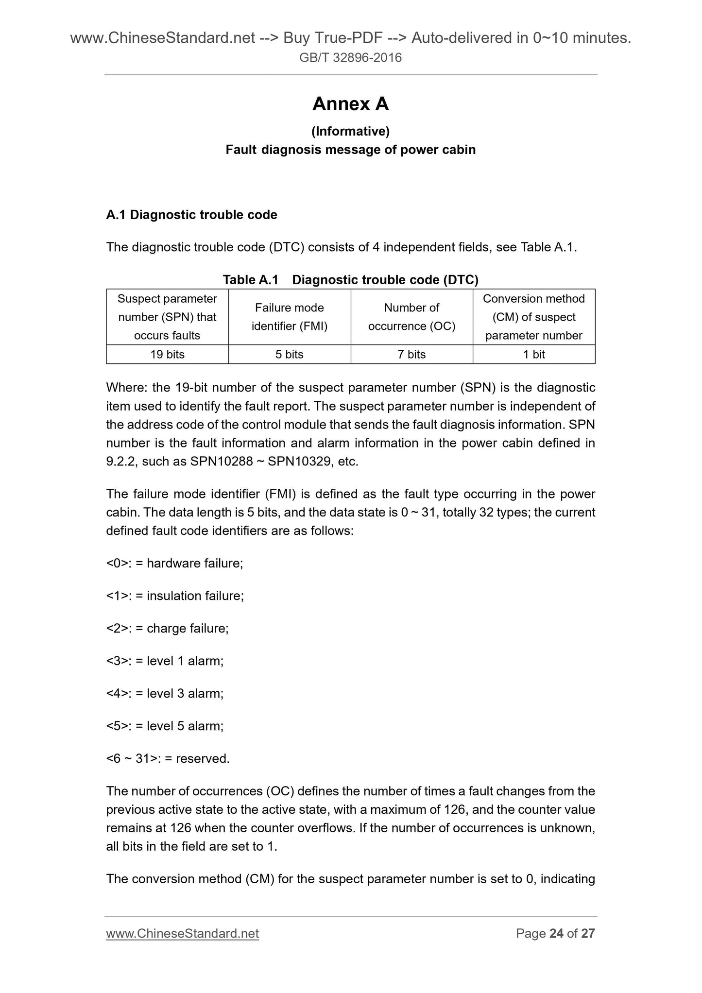
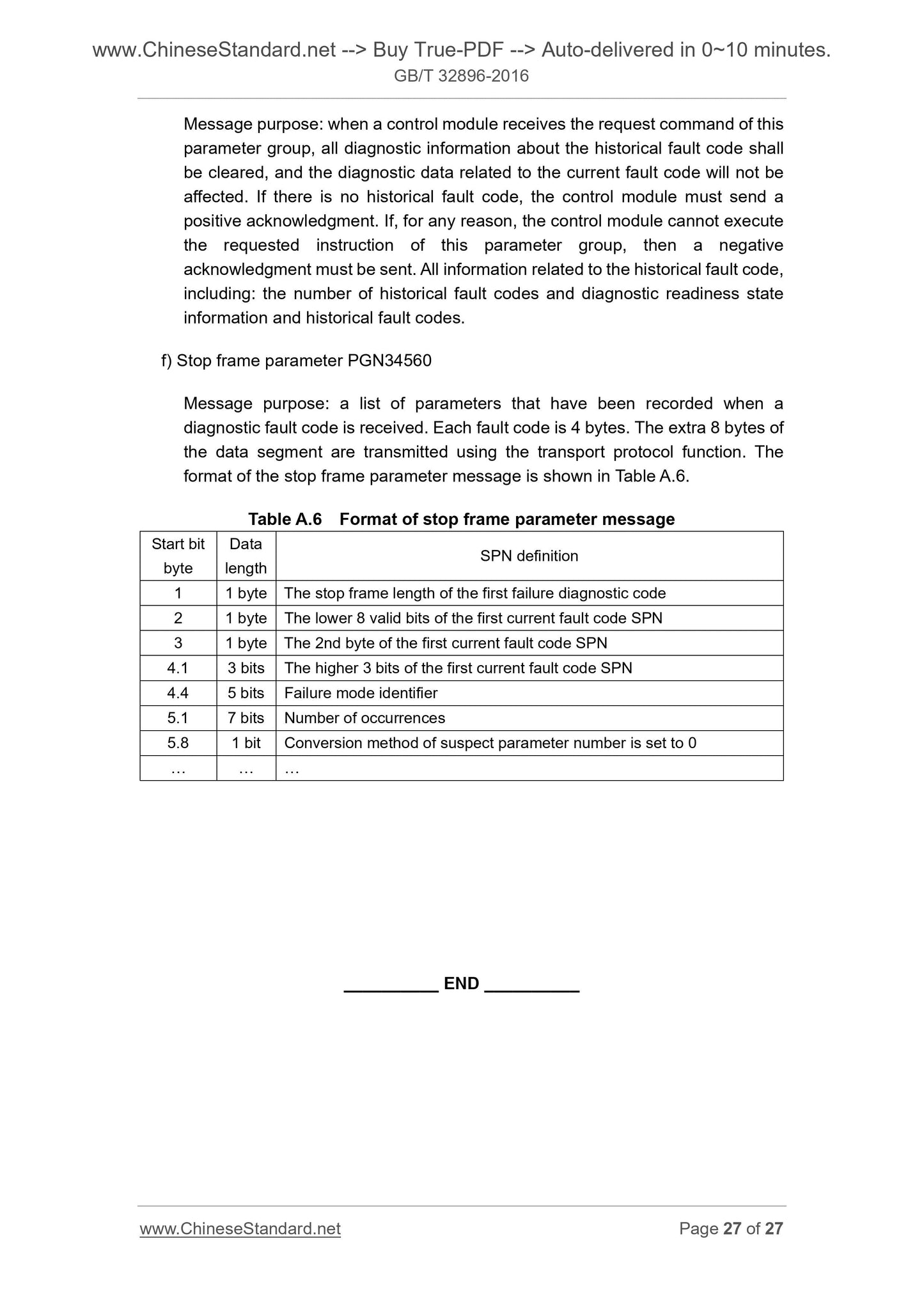
Preview True-PDF (Reload/Scroll if blank)

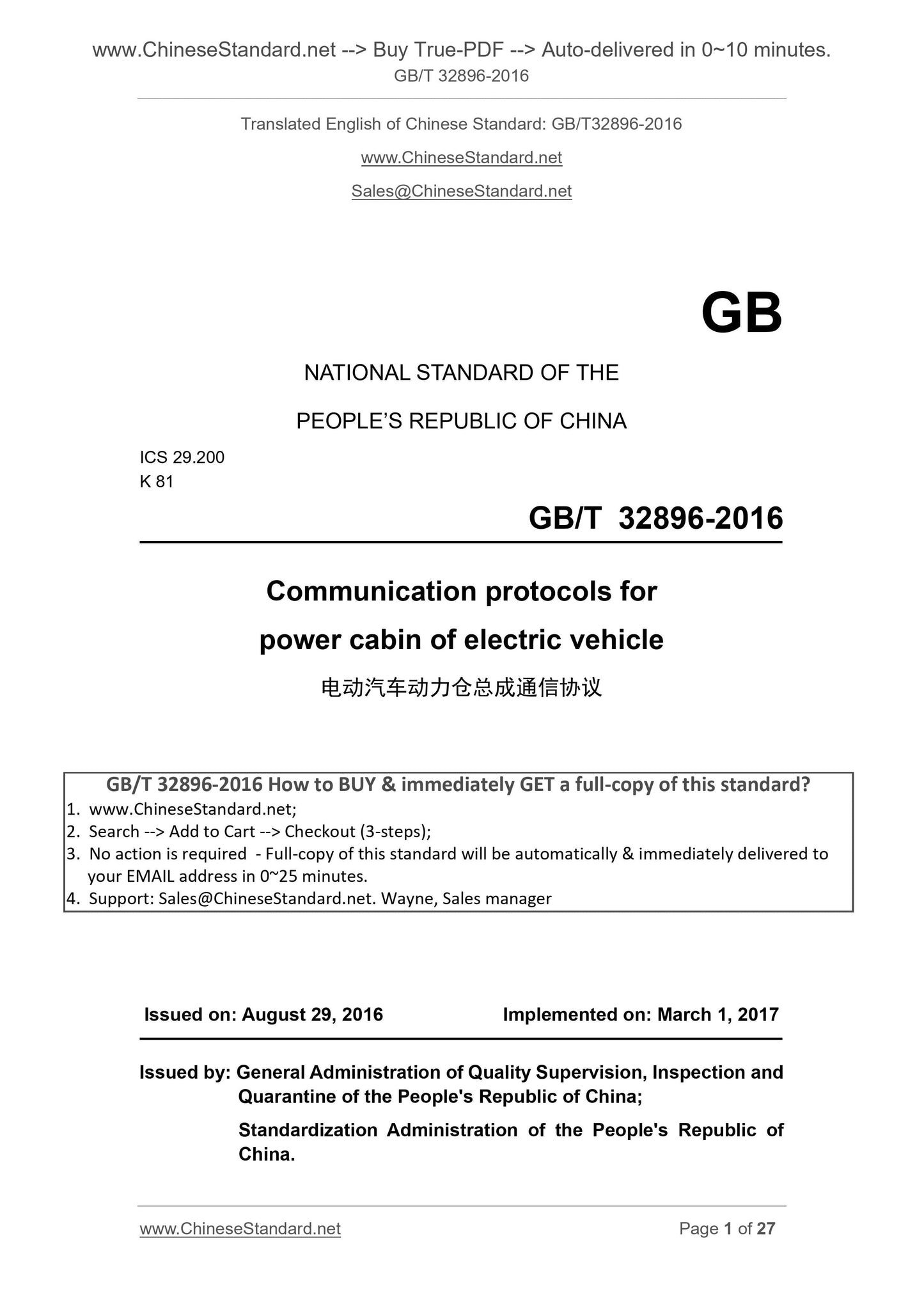
GB/T 32896-2016: Communication protocols for power cabin of electric vehicle
GB/T 32896-2016
GB
NATIONAL STANDARD OF THE
PEOPLE’S REPUBLIC OF CHINA
ICS 29.200
K 81
Communication protocols for
power cabin of electric vehicle
ISSUED ON. AUGUST 29, 2016
IMPLEMENTED ON. MARCH 1, 2017
Issued by. General Administration of Quality Supervision, Inspection and
Quarantine of the People's Republic of China;
Standardization Administration of the People's Republic of
China.
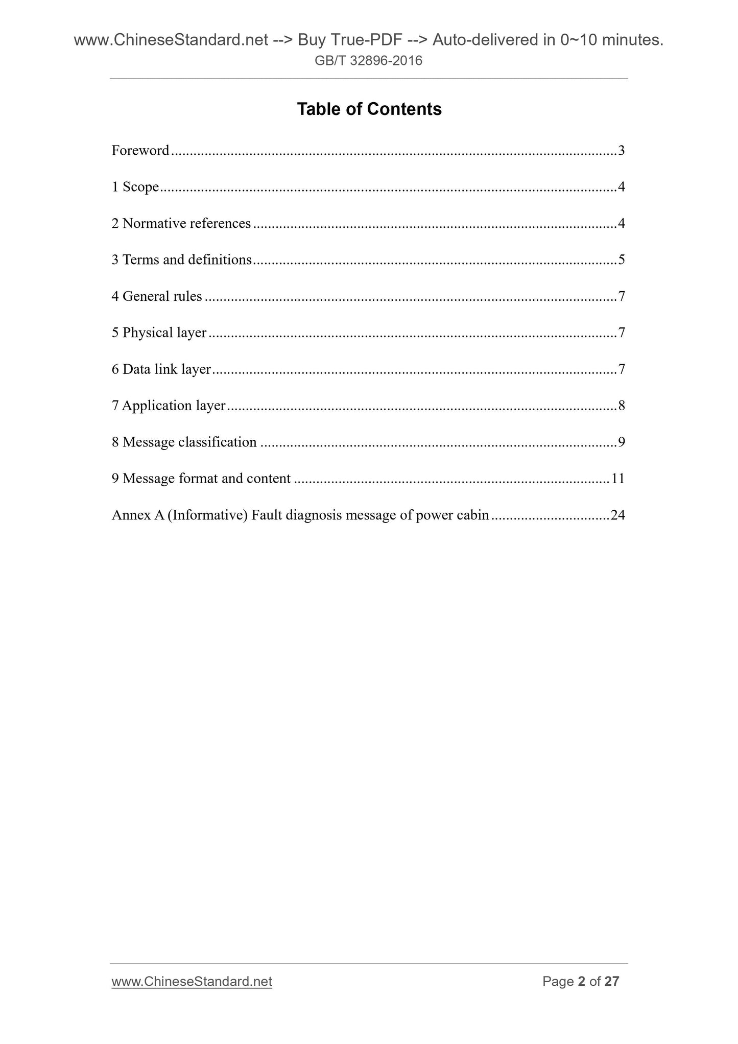
Table of Contents
Foreword ... 3
1 Scope ... 4
2 Normative references ... 4
3 Terms and definitions ... 5
4 General rules ... 7
5 Physical layer ... 7
6 Data link layer ... 7
7 Application layer ... 8
8 Message classification ... 9
9 Message format and content ... 11
Annex A (Informative) Fault diagnosis message of power cabin ... 24
Foreword
This Standard was drafted according to the rules given in GB/T 1.1-2009.
This Standard was proposed by and shall be under the jurisdiction of China Electricity
Council.
Main drafting organizations of this Standard. State Grid Corporation of China, State
Grid Zhejiang Electric Power Company, XJ Group Co., Ltd., State Grid Information and
Telecommunication Co., Ltd., State Grid Electric Power Research Institute, China
Electric Power Research Institute.
Main drafters of this Standard. Su Shengxin, Shen Jianxin, Wu Bin, Shi Shuanglong,
Chen Feng, Zhang Fan, Lin Xiaobin, Zhang Pengfei, Li Fengfeng, Yu Wenbin, Li
Yunfeng, Wu Zhijun, Zhao Xiang, Wu Yuming, Hu Jinyong.
Communication protocols for
power cabin of electric vehicle
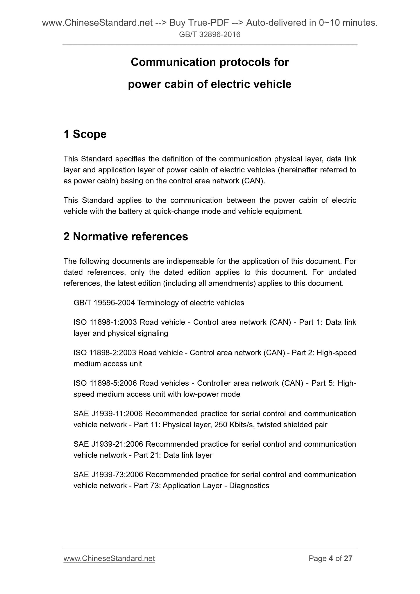
1 Scope
This Standard specifies the definition of the communication physical layer, data link
layer and application layer of power cabin of electric vehicles (hereinafter referred to
as power cabin) basing on the control area network (CAN).
This Standard applies to the communication between the power cabin of electric
vehicle with the battery at quick-change mode and vehicle equipment.
2 Normative references
The following documents are indispensable for the application of this document. For
dated references, only the dated edition applies to this document. For undated
references, the latest edition (including all amendments) applies to this document.
GB/T 19596-2004 Terminology of electric vehicles
ISO 11898-1.2003 Road vehicle - Control area network (CAN) - Part 1. Data link
layer and physical signaling
ISO 11898-2.2003 Road vehicle - Control area network (CAN) - Part 2. High-speed
medium access unit
ISO 11898-5.2006 Road vehicles - Controller area network (CAN) - Part 5. High-
speed medium access unit with low-power mode
SAE J1939-11.2006 Recommended practice for serial control and communication
vehicle network - Part 11. Physical layer, 250 Kbits/s, twisted shielded pair
SAE J1939-21.2006 Recommended practice for serial control and communication
vehicle network - Part 21. Data link layer
SAE J1939-73.2006 Recommended practice for serial control and communication
vehicle network - Part 73. Application Layer - Diagnostics
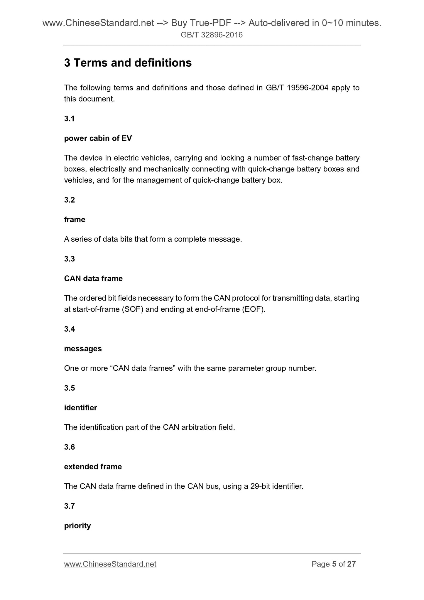
3 Terms and definitions
The following terms and definitions and those defined in GB/T 19596-2004 apply to
this document.
3.1
power cabin of EV
The device in electric vehicles, carrying and locking a number of fast-change battery
boxes, electrically and mechanically connecting with quick-change battery boxes and
vehicles, and for the management of quick-change battery box.
3.2
frame
A series of data bits that form a complete message.
3.3
CAN data frame
The ordered bit fields necessary to form the CAN protocol for transmitting data, starting
at start-of-frame (SOF) and ending at end-of-frame (EOF).
3.4
messages
One or more “CAN data frames” with the same parameter group number.
3.5
identifier
The identification part of the CAN arbitration field.
3.6
extended frame
The CAN data frame defined in the CAN bus, using a 29-bit identifier.
3.7
priority
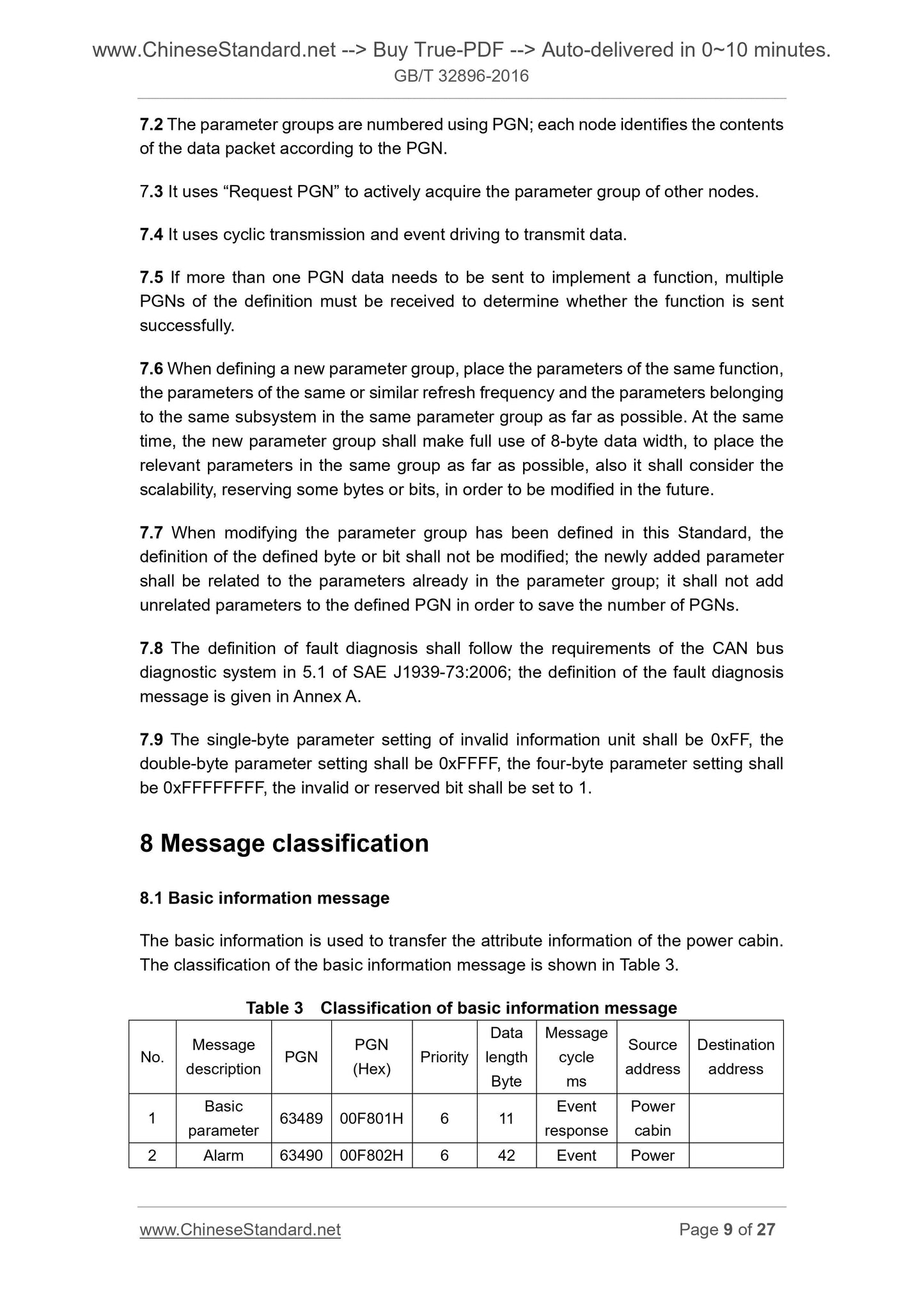
7.2 The parameter groups are numbered using PGN; each node identifies the contents
of the data packet according to the PGN.
7.3 It uses “Request PGN” to actively acquire the parameter group of other nodes.
7.4 It uses cyclic transmission and event driving to transmit data.
7.5 If more than one PGN data needs to be sent to implement a function, multiple
PGNs of the definition must be received to determine whether the function is sent
successfully.
7.6 When defining a new parameter group, place the parameters of the same function,
the parameters of the same or similar refresh frequency and the parameters belonging
to the same subsystem in the same parameter group as far as possible. At the same
time, the new parameter group shall make full use of 8-byte data width, to place the
relevant parameters in the same group as far as possible, also it shall consider the
scalability, reserving some bytes or bits, in order to be modified in the future.
7.7 When modifying the parameter group has been defined in this Standard, the
definition of the defined byte or bit shall not be modified; the newly added parameter
shall be related to the parameters already in the parameter group; it shall not add
unrelated parameters to the defined PGN in order to save the number of PGNs.
7.8 The definition of fault diagnosis shall follow the requirements of the CAN bus
diagnostic system in 5.1 of SAE J1939-73.2006; the definition of the fault diagnosis
message is given in Annex A.
7.9 The single-byte parameter setting of invalid information unit shall be 0xFF, the
double-byte parameter setting shall be 0xFFFF, the four-byte parameter setting shall
be 0xFFFFFFFF, the invalid or reserved bit shall be set to 1.
8 Message classification
8.1 Basic information message
The basic information is used to transfer the attribute information of the power cabin.
The classification of the basic information message is shown in Table 3.
Table 3 Classification of basic information message
No. Message description PGN
PGN
(Hex) Priority
Data
length
Byte
Message
cycle
ms
Source
address
Destination
address
1 Basic parameter 63489 00F801H 6 11
Event
response
Power
cabin
2 Alarm 63490 00F802H 6 42 Event Power
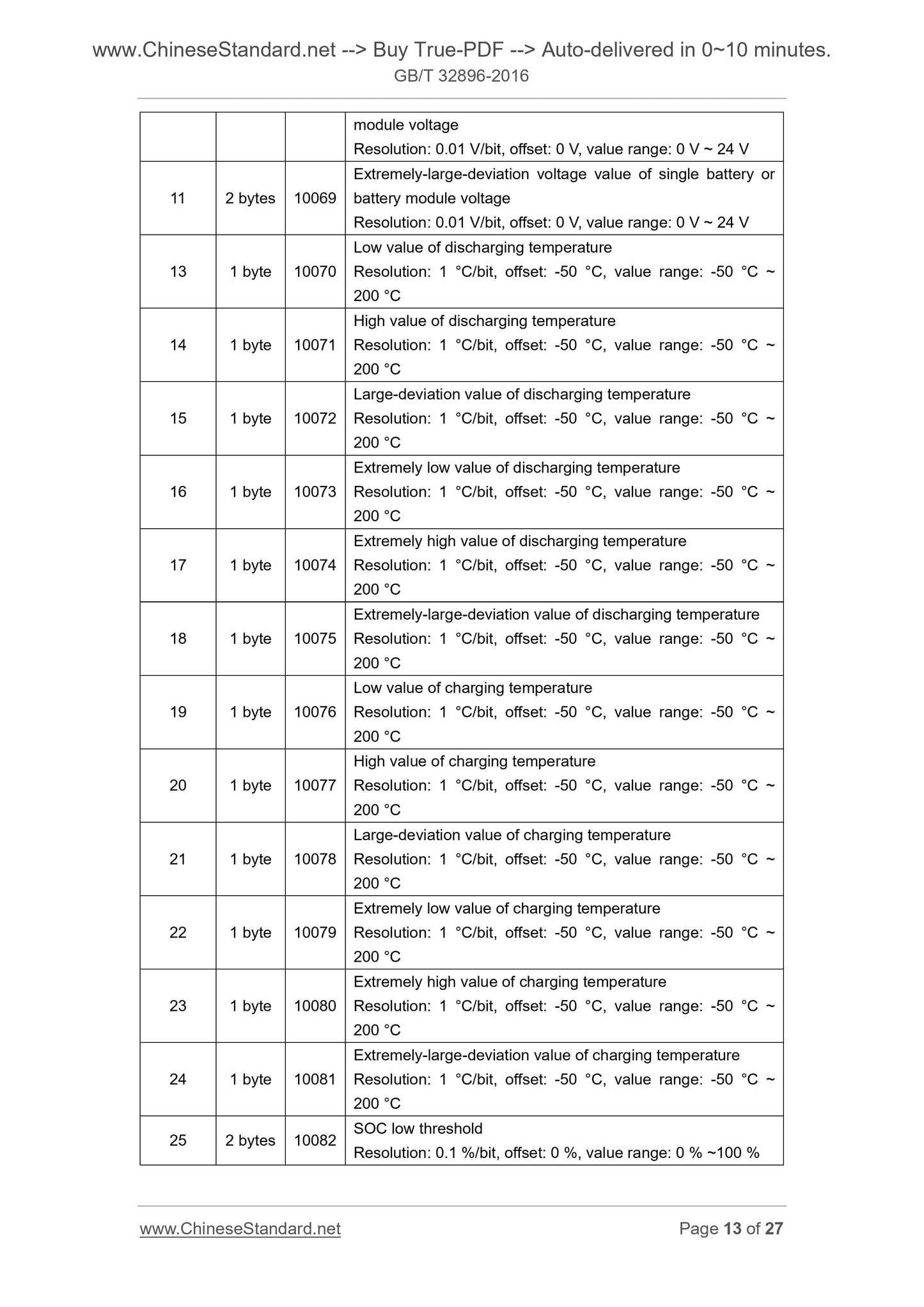
module voltage
Resolution. 0.01 V/bit, offset. 0 V, value range. 0 V ~ 24 V
11 2 bytes 10069
Extremely-large-deviation voltage value of single battery or
battery module voltage
Resolution. 0.01 V/bit, offset. 0 V, value range. 0 V ~ 24 V
13 1 byte 10070
Low value of discharging temperature
Resolution. 1 °C/bit, offset. -50 °C, value range. -50 °C ~
200 °C
14 1 byte 10071
High value of discharging temperature
Resolution. 1 °C/bit, offset. -50 °C, value range. -50 °C ~
200 °C
15 1 byte 10072
Large-deviation value of discharging temperature
Resolution. 1 °C/bit, offset. -50 °C, value range. -50 °C ~
200 °C
16 1 byte 10073
Extremely low value of discharging temperature
Resolution. 1 °C/bit, offset. -50 °C, value range. -50 °C ~
200 °C
17 1 byte 10074
Extremely high value of discharging temperature
Resolution. 1 °C/bit, offset. -50 °C, value range. -50 °C ~
200 °C
18 1 byte 10075
Extremely-large-deviation value of discharging temperature
Resolution. 1 °C/bit, offset. -50 °C, value range. -50 °C ~
200 °C
19 1 byte 10076
Low value of charging temperature
Resolution. 1 °C/bit, offset. -50 °C, value range. -50 °C ~
200 °C
20 1 byte 10077
High value of charging temperature
Re...
View full details