1
/
of
5
www.ChineseStandard.us -- Field Test Asia Pte. Ltd.
GB/T 324-2008 English PDF (GB/T324-2008)
GB/T 324-2008 English PDF (GB/T324-2008)
Regular price
$70.00
Regular price
Sale price
$70.00
Unit price
/
per
Shipping calculated at checkout.
Couldn't load pickup availability
GB/T 324-2008: Weld symbolic representation on drawings
Delivery: 9 seconds. Download (and Email) true-PDF + Invoice.Get Quotation: Click GB/T 324-2008 (Self-service in 1-minute)
Newer / historical versions: GB/T 324-2008
Preview True-PDF
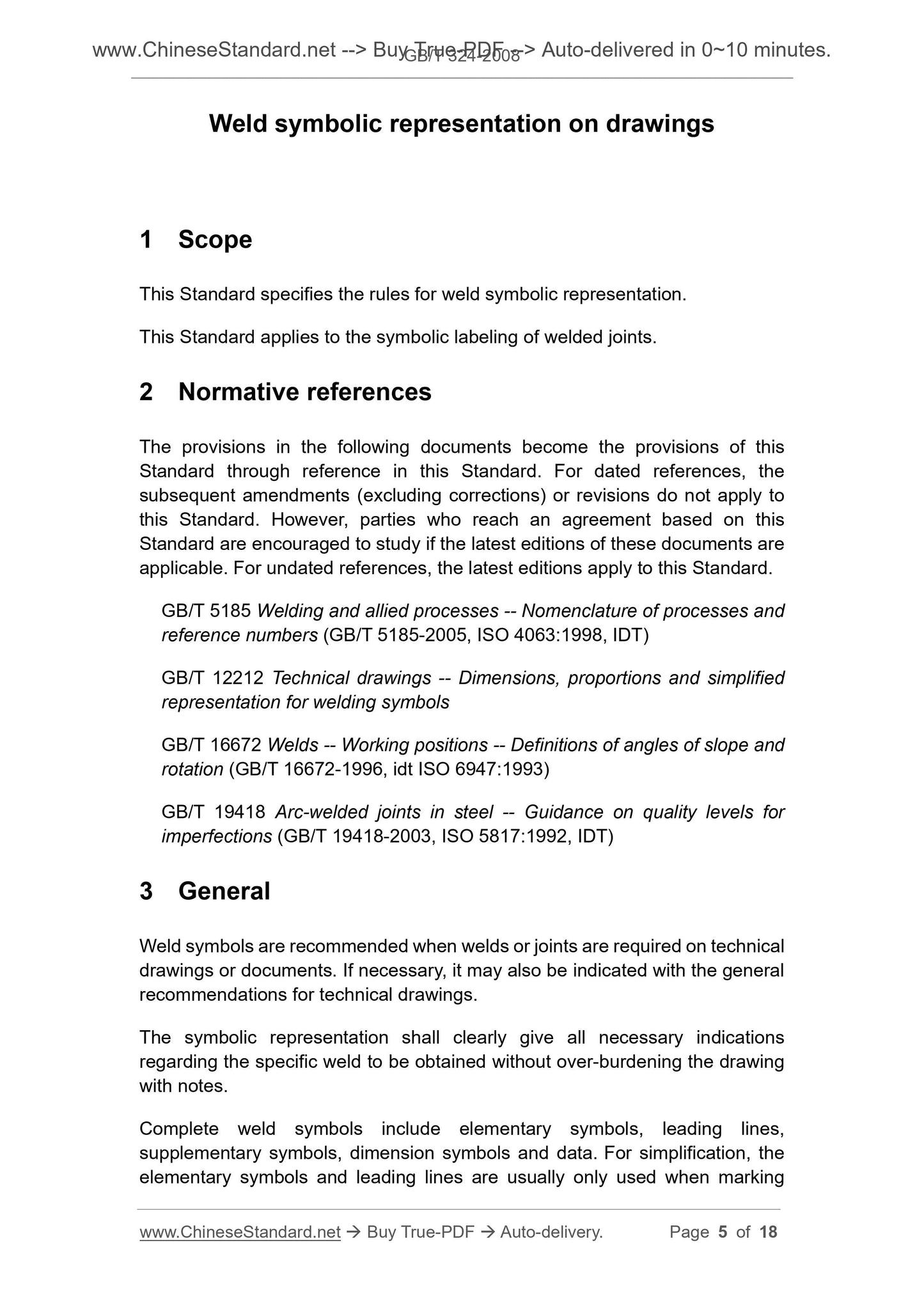
Scope
This Standard specifies the rules for weld symbolic representation.This Standard applies to the symbolic labeling of welded joints.
Basic Data
| Standard ID | GB/T 324-2008 (GB/T324-2008) |
| Description (Translated English) | Weld symbolic representation on drawings |
| Sector / Industry | National Standard (Recommended) |
| Classification of Chinese Standard | J04;J33 |
| Classification of International Standard | 25.160.01 |
| Word Count Estimation | 15,122 |
| Date of Issue | 2008-06-26 |
| Date of Implementation | 2009-01-01 |
| Older Standard (superseded by this standard) | GB/T 324-1988 |
| Quoted Standard | GB/T 5185; GB/T 12212; GB/T 16672; GB/T 19418 |
| Adopted Standard | ISO 2553-1992, MOD |
| Regulation (derived from) | National Standard Approval Announcement 2008 No.11 (Total No.124) |
| Issuing agency(ies) | General Administration of Quality Supervision, Inspection and Quarantine of the People's Republic of China, Standardization Administration of the People's Republic of China |
| Summary | This standard specifies the representation rules weld symbols. This standard applies to balloons welded joints. |
Share