Skip to product information
1 of 12

PayPal, credit cards. Download editable-PDF and invoice in 1 second!

GB/T 32224-2015 English PDF (GBT32224-2015)

GB/T 32224-2015 English PDF (GBT32224-2015)

Regular price $320.00 USD
Regular price Sale price $320.00 USD
Sale Sold out
Shipping calculated at checkout.
Delivery: 3 seconds. Download true-PDF + Invoice.
Get Quotation: Click GB/T 32224-2015 (Self-service in 1-minute)
Historical versions (Master-website): GB/T 32224-2015
Preview True-PDF (Reload/Scroll-down if blank)

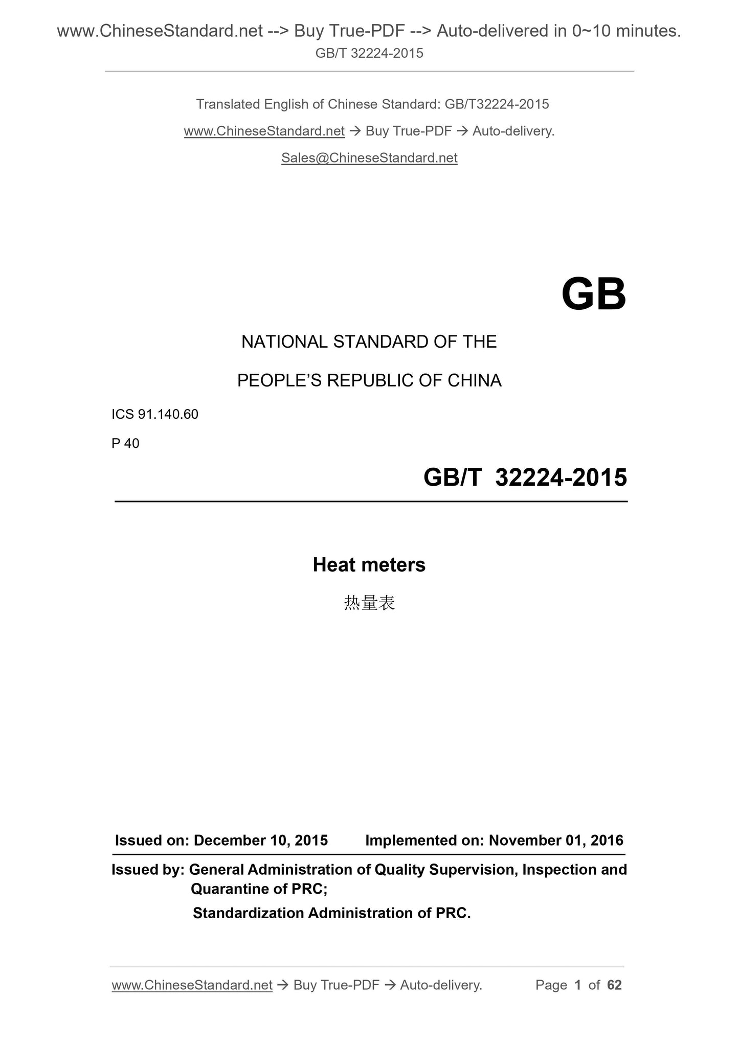
GB/T 32224-2015: Heat meters
GB/T 32224-2015
Heat meters
ICS 91.140.60
P40
National Standards of People's Republic of China
Heat meter
Released on December 10,.2015
Implementation of.2016-11-01
General Administration of Quality Supervision, Inspection and Quarantine of the People's Republic of China
China National Standardization Administration issued
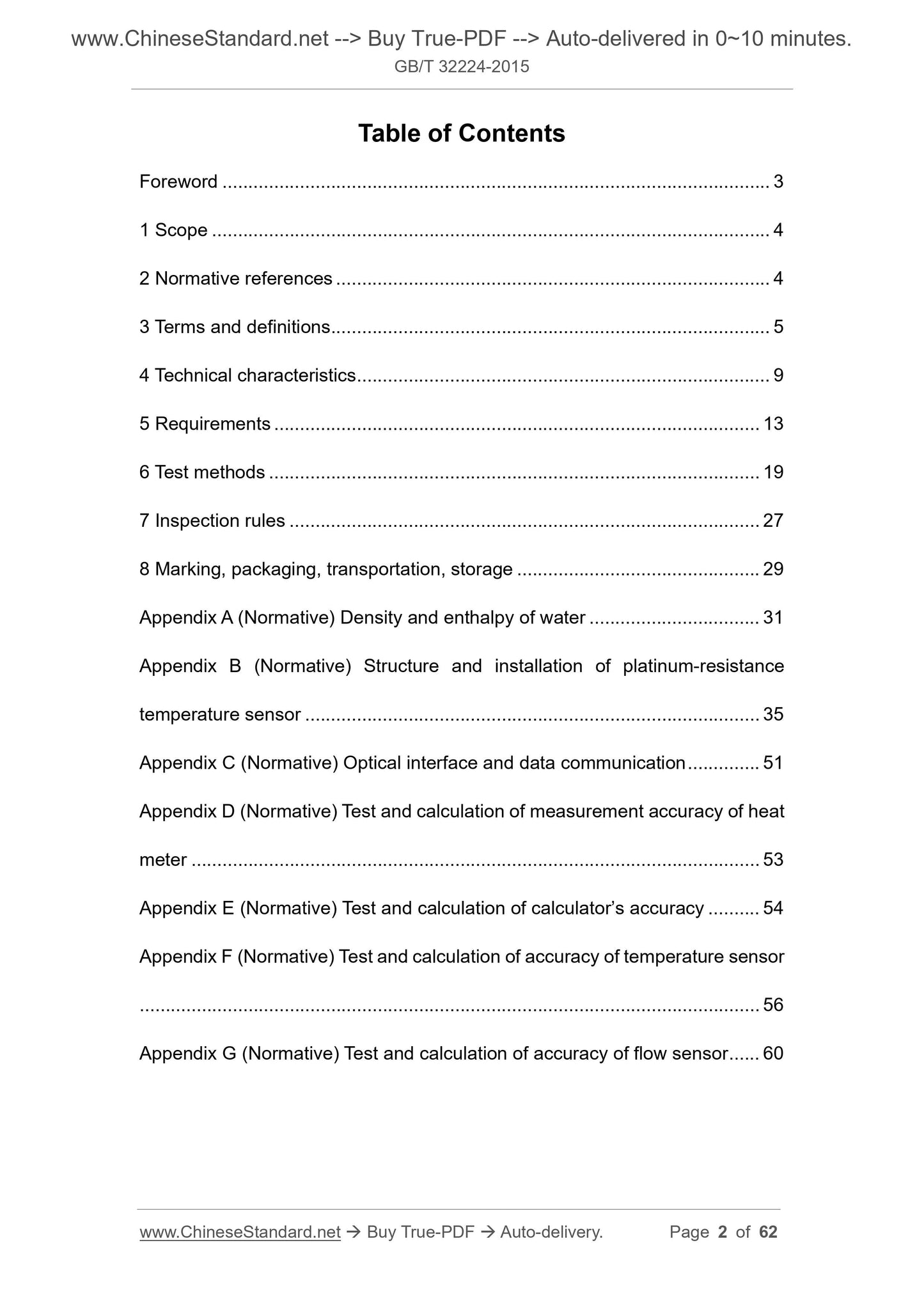
Content
Foreword III
1 range 1
2 Normative references 1
3 Terms and Definitions 1
4 Technical characteristics 3
5 Requirements 6
6 Test method 10
7 Inspection rules 15
8 Marking, packaging, transport and storage 16
Appendix A (Normative) Water Density and Depreciation Table 18
Appendix B (Normative) Structure and Installation of Platinum Resistance Temperature Sensors 22
Appendix C (Normative) Optical Interfaces and Data Communications 36
Appendix D (Normative Appendix) Test and Calculation of Heat Meter Measurement Accuracy 38
Appendix E (Normative) Test and Calculation of Calculator Accuracy 39
Appendix F (Normative) Test and Calculation of Temperature Sensor Accuracy 41
Appendix G (Normative) Test and Calculation of Flow Sensor Accuracy 43
Foreword
This standard was drafted in accordance with the rules given in GB/T 1.1-2009.
This standard was proposed by the Ministry of Housing and Urban-Rural Development of the People's Republic
This standard is under the jurisdiction of the National Urban Heating Standardization Technical Committee (SAC/TC455).
This standard was drafted. Urban Construction Research Institute, Guangzhou Baicheng Intelligent Technology Co., Ltd., Shenyang Airlines Thermal Measurement Technology Co., Ltd.
Tangshan Huizhong Instrument Co., Ltd., Liaoning Sikai Technology Co., Ltd., Shenyang Jiade Lianyi Energy Technology Co., Ltd., Jiu Mao Auto
(Dalian) Co., Ltd., Lierda Technology Co., Ltd., Beijing Zhenlan Instrument Co., Ltd., Beijing Debao Haote Energy Technology Co., Ltd.
Henan Xintian Technology Co., Ltd., Tianjin Metrology Supervision and Testing Science Research Institute, Xuzhou Runwu Technology Development Co., Ltd., Beijing Tian Ruixiang
Instrumentation Co., Ltd., Siemens (China) Co., Ltd.
The main drafters of this standard. Lu Shijian, Yang Jian, Tan Wensheng, Ni Zhijun, Shi Jianjun, Wang Kuilin, Zhang Lixin, Feng Lei, Liu Wei, Liang Yuan, Zhang Lixiang,
Yang Yi, Chu Dongting, Wang Song, Xu Defeng, Wang Baobing.
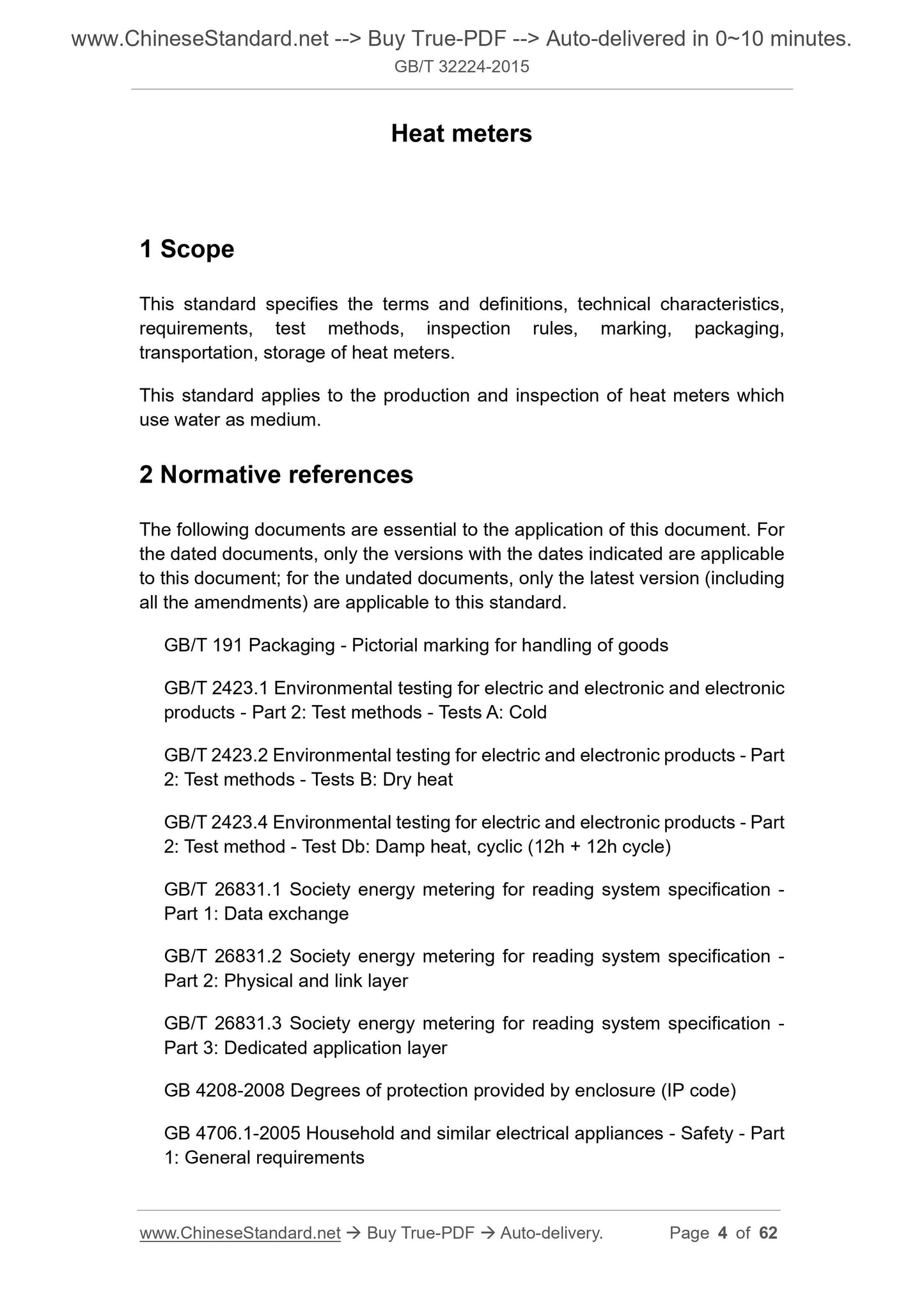
Heat meter
1 Scope
This standard specifies the terms and definitions, technical characteristics, requirements, test methods, inspection rules, marking, packaging, transportation and storage of heat meters.
This standard applies to the production and inspection of heat meters using medium water.
2 Normative references
The following documents are indispensable for the application of this document. For dated references, only dated versions apply to this article.
Pieces. For undated references, the latest edition (including all amendments) applies to this document.
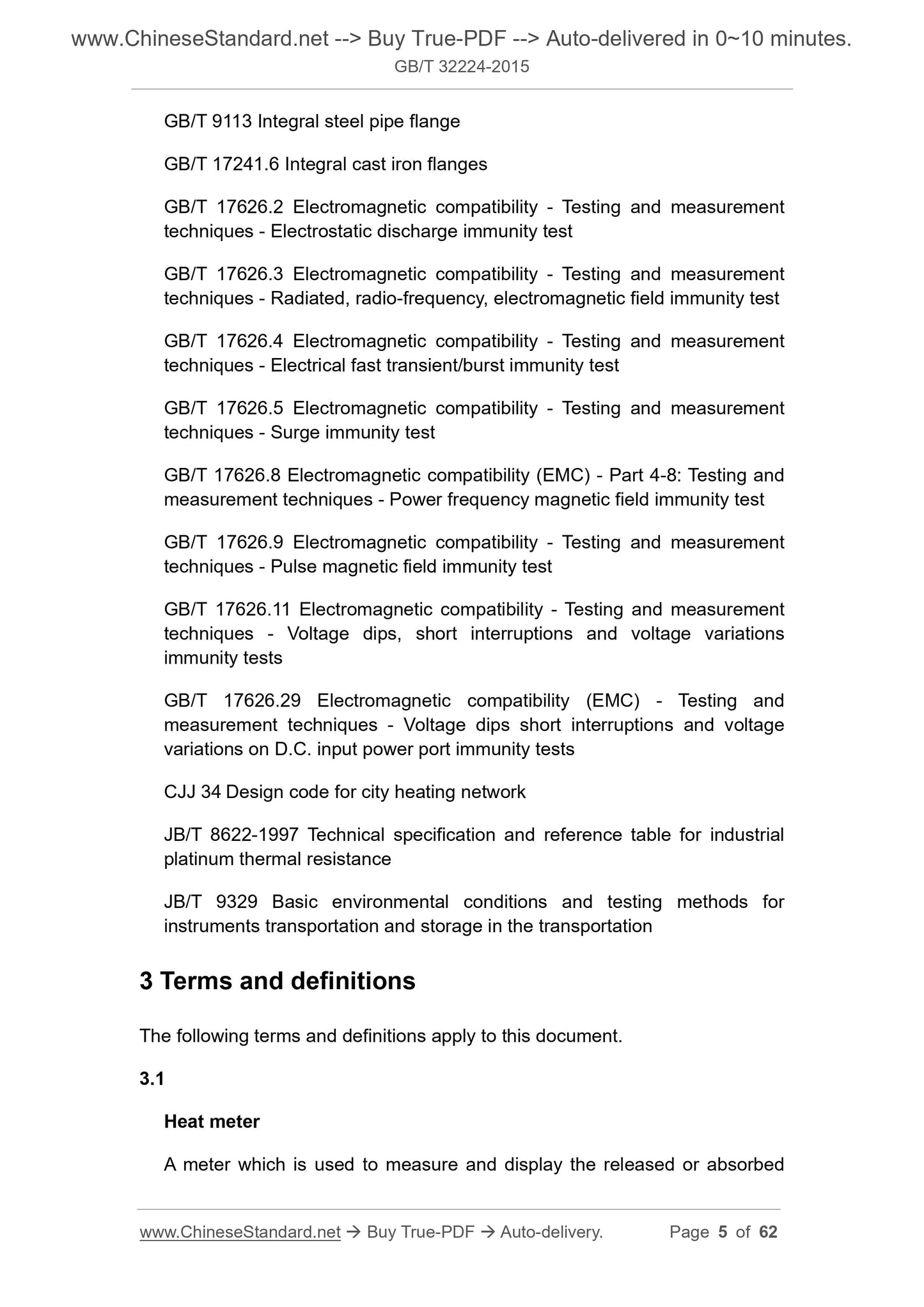
GB/T 191 packaging storage and transportation icon
GB/T 2423.1 Environmental testing of electrical and electronic products - Part 2. Test methods Test A. Low temperature
GB/T 2423.2 Environmental testing of electrical and electronic products - Part 2. Test methods Test B. High temperature
GB/T 2423.4 Environmental testing of electric and electronic products - Part 2. Test method Test Db. alternating heat and damp 12h 12h cycle
GB/T 26831.1 Community energy metering and copying system specification Part 1. Data exchange
GB/T 26831.2 Community Energy Metering and Copying System Specification Part 2. Physical Layer and Link Layer
GB/T 26831.3 Community Energy Metering and Copying System Specification Part 3. Professional Application Layer
GB 4208-2008 Shell protection rating (IP code)
GB 4706.1-2005 Safety of household and similar electrical appliances - Part 1. General requirements
GB/T 9113 integral steel pipe flange
GB/T 17241.6 integral cast iron flange
GB/T 17626.2 Electromagnetic compatibility test and measurement technology Electrostatic discharge immunity test
GB/T 17626.3 Electromagnetic compatibility test and measurement technology RF electromagnetic field radiation immunity test
GB/T 17626.4 Electromagnetic compatibility test and measurement technology Electrical fast transient burst immunity test
GB/T 17626.5 Electromagnetic compatibility test and measurement technology Surge (impact) immunity test
GB/T 17626.8 Electromagnetic compatibility test and measurement technology power frequency magnetic field immunity test
GB/T 17626.9 Electromagnetic compatibility test and measurement technology Pulse magnetic field immunity test
GB/T 17626.11 Electromagnetic compatibility test and measurement techniques Immunity test for voltage dips, short interruptions and voltage changes
GB/T 17626.29 Electromagnetic compatibility test and measurement technology DC power input port voltage dip, short interruption and voltage change
Immunity test
CJJ34 town heating pipe network design specification
JB/T 8622-1997 Industrial Platinum Thermal Resistance Technical Conditions and Index Table
JB/T 9329 Instrumentation, transportation, transportation and storage, basic environmental conditions and test methods
3 Terms and definitions
The following terms and definitions apply to this document.
3.1
Heat meter heatmeter
A meter used to measure and display the release or absorption of thermal energy by water flowing through a heat exchange system.
3.2
Cooling gauge coolingmeter
A meter used to measure and display the amount of heat absorbed by water flowing through a heat exchange system.
3.3
Cold heat meter metersforheatingandcooling
A meter used to measure and display the release and absorption of thermal energy by water flowing through a heat exchange system.
3.4
Integral heat meter completeheatmeter
An indecomposable heat meter consisting of components such as flow sensors, calculators, and paired temperature sensors.
3.5
Combined heat meter combinedheatmeter
A heat meter that combines flow sensors, calculators, and paired temperature sensors.
3.6
Flow sensor flowsensor
A component that is installed in a heat exchange system to collect water flow and send a flow signal.
3.7
Temperature sensor temperaturesensor
A component that is installed in a heat exchange system to collect the temperature of water and emit a temperature signal.
3.8
Paired temperature sensor temperaturesensorpair
On the same heat meter, the pair of metering characteristics of the water supply and return water temperature of the heat exchange system are respectively measured to be consistent or similar.
Degree sensor.
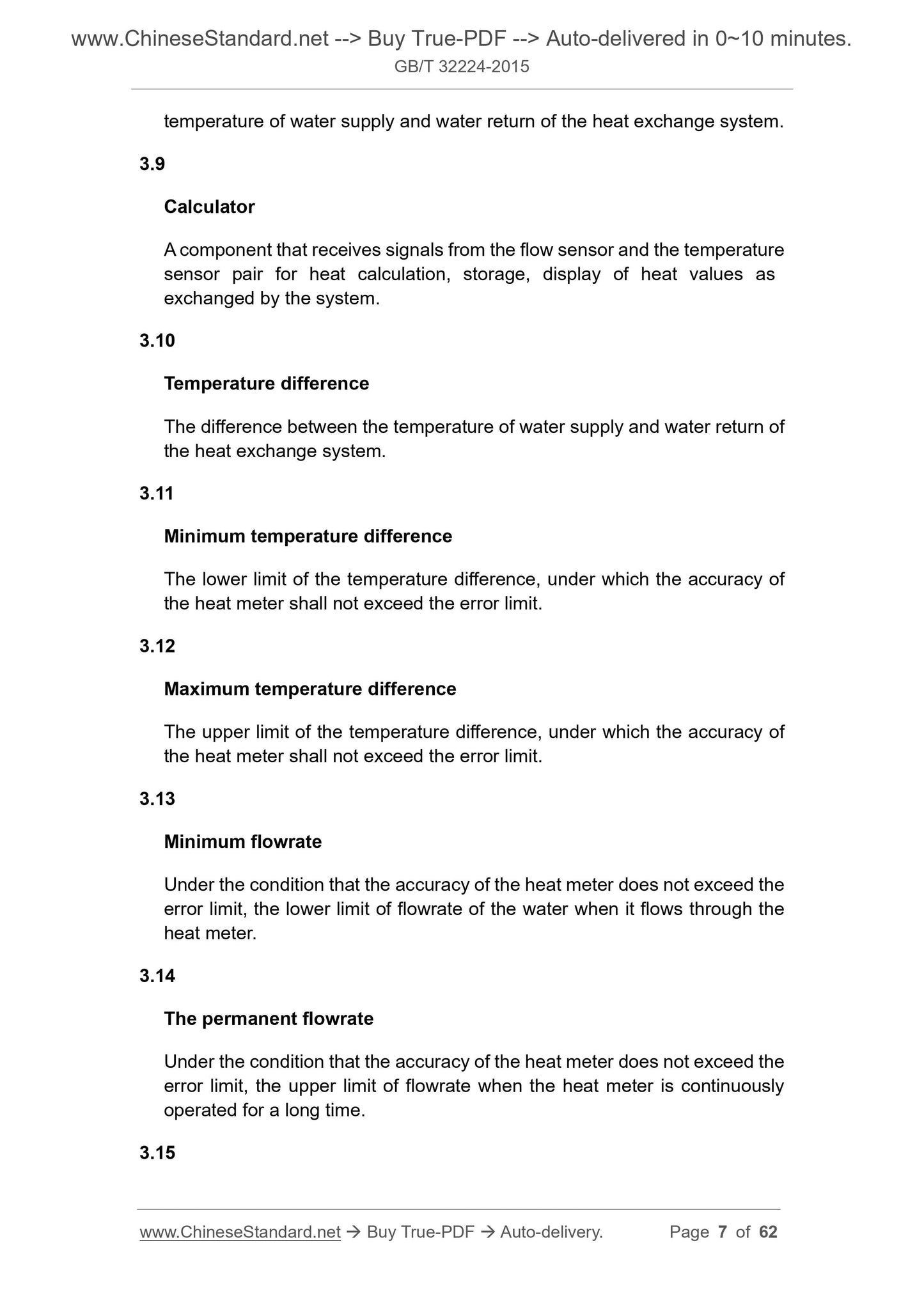
3.9
Calculator calculator
Receiving signals from flow sensors and paired temperature sensors for heat calculation, storage, and display of thermal values exchanged by the system
component.
3.10
Temperature difference
The temperature difference between the water supply and the return water of the heat exchange system.
3.11
Minimum temperature difference minimumtemperaturedifference
The lower limit of the temperature difference. Under this temperature difference, the accuracy of the heat meter should not exceed the error limit.
3.12
Maximum temperature difference maximumtemperaturedifference
The upper limit of the temperature difference. Under this temperature difference, the accuracy of the heat meter should not exceed the error limit.
3.13
Minimum flow minimumflow-rate
The lower limit flow rate of water flowing through the heat meter under the condition that the accuracy of the heat meter does not exceed the error limit.
3.14
Commonly used traffic thepermanentflow-rate
The upper limit flow rate when the heat meter is continuously operated for a long time under the condition that the accuracy of the heat meter does not exceed the error limit.
3.15
Maximum flow maximumflow-rate
Under the condition that the accuracy of the heat meter does not exceed the error limit, the pole of the heat meter is operated in a short time (< 1h/d; < 200h/y).
Limited flow.
3.16
Cumulative flow totalvolume
The sum of the volume or mass of water flowing through the heat meter.
3.17
Upper temperature limit thehighesttemperature
The maximum temperature that water is allowed to reach when the accuracy of the heat meter does not exceed the error limit.
3.18
Lower temperature limit thelowesttemperature
The lowest temperature allowed for water when the accuracy of the heat meter does not exceed the error limit.
3.19
Maximum allowable working pressure maximumadfriendlyworkingpressure
The maximum working pressure that the heat meter can withstand when the upper temperature limit is continuously operated.
3.20
Allow pressure loss admissiblepressureloss
The limit of the pressure loss of water flowing through the heat meter at the usual flow rate.
3.21
Maximum metering thermal power maximumthermalpower
When the accuracy of the heat meter does not exceed the error limit, the maximum value that the thermal power may reach is measured.
4 Technical characteristics
4.1 Calorie measurement
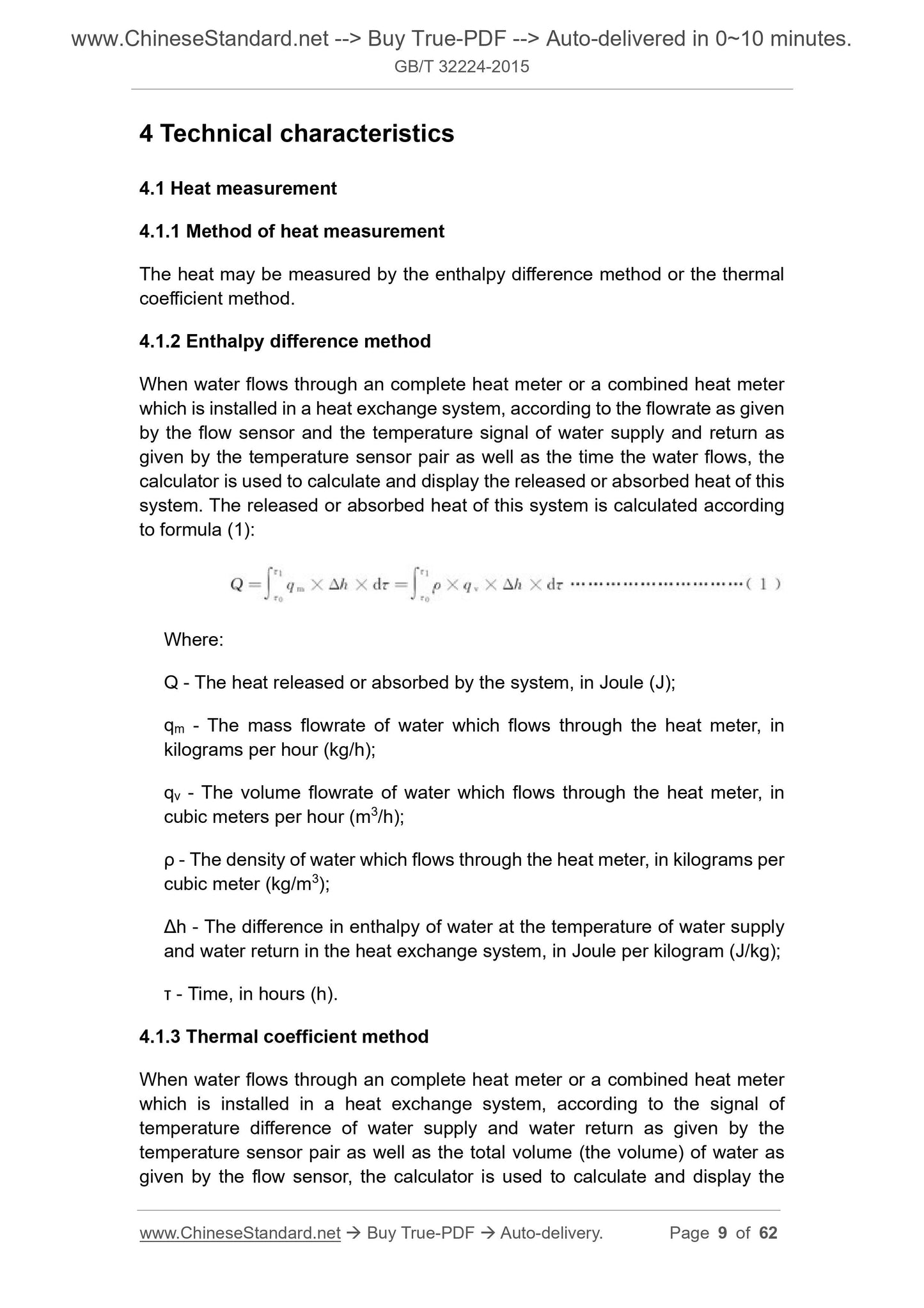
4.1.1 Thermal measurement method
The calorific value can be measured by the enthalpy difference method or the thermal coefficient method.
4.1.2 焓 difference method
When the water flows through the integrated heat meter or combined heat meter installed in the heat exchange system, according to the flow rate and distribution given by the flow sensor
The return water temperature signal given to the temperature sensor and the time the water flows through are calculated by the calculator and show the release or absorption of the system.
The heat. The heat released or absorbed by the system is calculated according to formula (1).
Q=∫
Τ1
Τ0
Qm×Δh×dτ=∫
Τ1
Τ0
ρ×qv×Δh×dτ(1)
In the formula.
Q --- The amount of heat released or absorbed by the system, in units of coke (J);
Qm --- mass flow of water through the heat meter, in kilograms per hour (kg/h);
Qv --- volumetric flow of water through the heat meter, in cubic meters per hour (m3/h);
ρ --- the density of water flowing through the heat meter in kilograms per cubic meter (kg/m3);
Δh---the difference in the enthalpy of water in the heat exchange system water supply and return water temperature, the unit is per kilogram (J/kg);
τ --- time in hours (h).
4.1.3 Thermal coefficient method
When water flows through an integrated heat meter or a combined heat meter in a heat exchange system, the supply and return water are given according to the paired temperature sensor.
The temperature difference signal, and the cumulative flow (volume) of water given by the flow sensor, is calculated by the calculator and shows the heat released or absorbed by the system.
the amount. The heat released or absorbed by the system is calculated according to equations (2) and (3).
Q=∫
V1
V0
k × Δθ × dV (2)
k=ρ
Δh
Δθ
(3)
In the formula.
V -- the volume of water flowing through the heat meter in cubic meters (m3);
Δθ---the temperature difference between the water supply and the return water in the heat exchange system, the unit is open (K);
k --- Thermal coefficient in units of coke per cubic meter (J/m3·K).
4.1.4 Density and value of 焓
The density and enthalpy values in equations (1) and (3) shall be selected in accordance with Appendix A. When the temperature is non-integer, the density and enthalpy should be interpolated
Corrected.
4.2 Structure and materials
4.2.1 Structure of the heat meter
The heat meter consists of a flow sensor, a paired temperature sensor and a calculator. A filter unit should be installed at the inlet of the heat meter.
4.2.2 Structure and material of flow sensor
The flow sensor should be selected according to the conditions of temperature, pressure, etc., and should be of suitable structural form and material, and should have sufficient mechanical strength.
And corrosion resistance.
4.2.3 Structure and material of temperature sensor
4.2.3.1 Temperature measurement should be carried out with a paired platinum resistance temperature sensor. The structure and installation should comply with the provisions of Appendix B.
4.2.3.2 When the temperature sensor and the pipeline are threaded, the thread specifications shall comply with the provisions of Appendix B.
4.2.3.3 The insulation performance of the temperature sensor shall comply with the provisions of JB/T 8622-1997.
4.3 Traffic
4.3.1 The common flow rate of the heat meter should meet the requirements of Table 1.
4.3.2 The ratio of common flow to minimum flow should be 25, 50, 100, 250. Commonly used heat flow less than or equal to 10m3/h, commonly used
The ratio of flow to minimum flow should not be less than 50.
4.3.3 The ratio of maximum flow to common flow should not be less than 2.
4.4 Temperature difference
The ratio of the maximum temperature difference to the minimum temperature difference of the heat meter should not be less than 10. The minimum temperature difference should be 1K, 2K, 3K; the minimum temperature difference of the cold gauge
Should not be greater than 2K.
4.5 Connection size and method
4.5.1 The interface size and thread connection of the flow sensor can be performed as specified in Table 1, Table 2 and Figure 1.
4.5.2 Heat meters with a working pressure greater than 1.6 MPa or a nominal diameter greater than DN40 shall be flanged and their flange specifications shall be in accordance with
GB/T 9113 or GB/T 17241.6.
Table 1 Common flow and flow sensor connection sizes and methods
5 requirements
5.1 Conditions of use
5.1.1 The water quality used in the heat meter shall comply with the provisions of CJJ34.
5.1.2 The use of heat meters is divided into four environmental categories, and the environmental conditions should meet the requirements of Table 3.
Table 3 Environmental conditions
Environmental conditions
Environmental category
ABCD
Temperature/°C 5~55 -25~55 5~55 -25~55
Relative humidity /% < 93 < 93 < 93 ≥93
Installation site The environment outside the building where the industrial environment may be soaked by water
Magnetic field range ordinary magnetic field common magnetic field magnetic field strength common magnetic field
5....
View full details