1
/
of
6
www.ChineseStandard.us -- Field Test Asia Pte. Ltd.
GB/T 32073-2015 English PDF (GB/T32073-2015)
GB/T 32073-2015 English PDF (GB/T32073-2015)
Regular price
$150.00
Regular price
Sale price
$150.00
Unit price
/
per
Shipping calculated at checkout.
Couldn't load pickup availability
GB/T 32073-2015: Non-destructive testing - Test method for measuring residual stress using ultrasonic critical refracted longitudinal wave
Delivery: 9 seconds. Download (and Email) true-PDF + Invoice.Get Quotation: Click GB/T 32073-2015 (Self-service in 1-minute)
Newer / historical versions: GB/T 32073-2015
Preview True-PDF
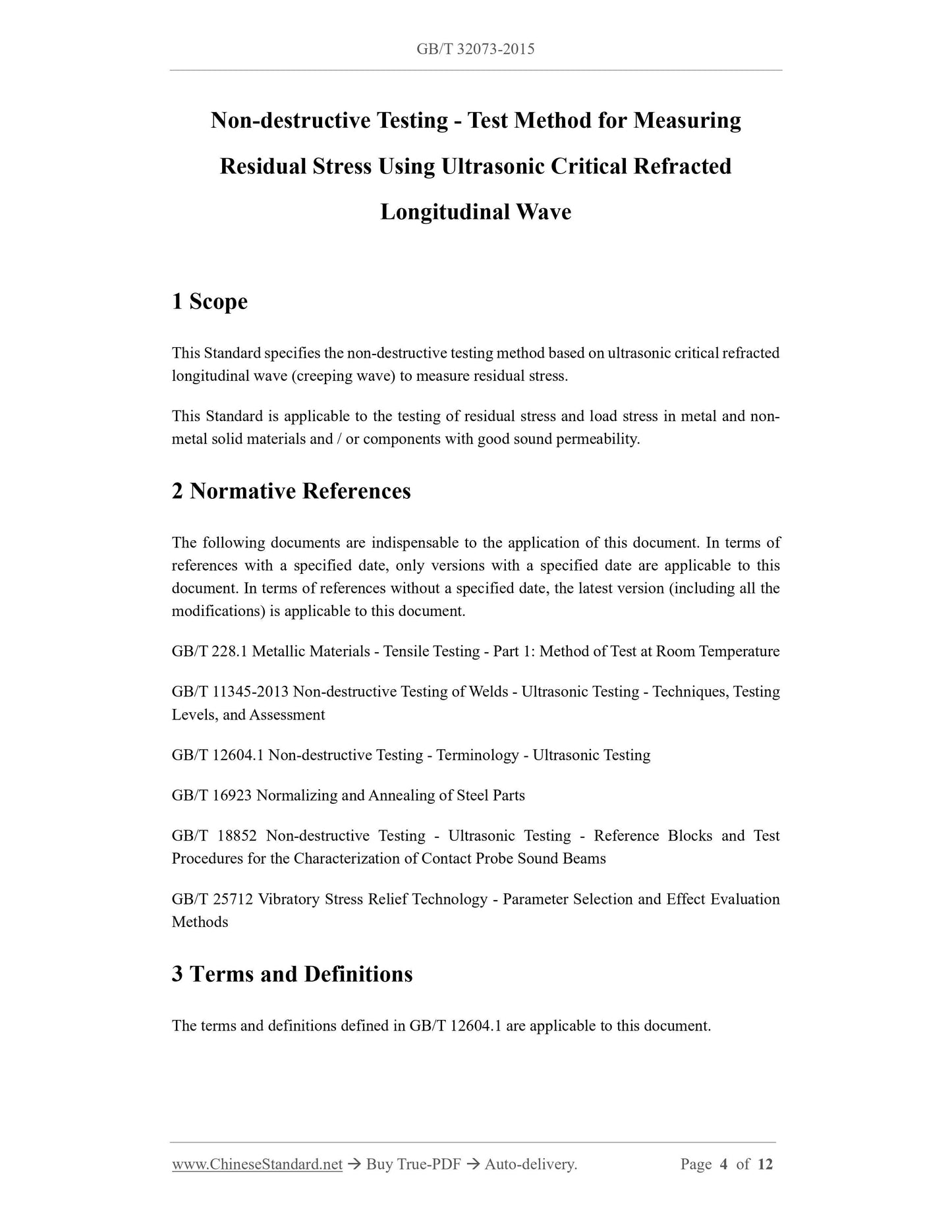
Scope
This Standard specifies the non-destructive testing method based on ultrasonic critical refractedlongitudinal wave (creeping wave) to measure residual stress.
This Standard is applicable to the testing of residual stress and load stress in metal and non-
metal solid materials and / or components with good sound permeability.
Basic Data
| Standard ID | GB/T 32073-2015 (GB/T32073-2015) |
| Description (Translated English) | Non-destructive testing - Test method for measuring residual stress using ultrasonic critical refracted longitudinal wave |
| Sector / Industry | National Standard (Recommended) |
| Classification of Chinese Standard | J04 |
| Classification of International Standard | 19.100 |
| Word Count Estimation | 8,871 |
| Date of Issue | 2015-10-09 |
| Date of Implementation | 2016-06-01 |
| Quoted Standard | GB/T 228.1; GB/T 11345-2013; GB/T 12604.1; GB/T 16923; GB/T 18852; GB/T 25712 |
| Regulation (derived from) | National Standard Announcement 2015 No.31 |
| Issuing agency(ies) | General Administration of Quality Supervision, Inspection and Quarantine of the People's Republic of China, Standardization Administration of the People's Republic of China |
| Summary | This Standard specifies the method based on ultrasonic NDT critically refracted longitudinal wave (creeping waves) measuring residual stress. This Standard applies to detect sound permeability good solid metallic and non-metallic materials and/or residual stress and load stress within the member. |
Share