Skip to product information
1 of 6

www.ChineseStandard.us -- Field Test Asia Pte. Ltd.

GB/T 31883-2015 English PDF (GB/T31883-2015)

GB/T 31883-2015 English PDF (GB/T31883-2015)

Regular price $160.00
Regular price Sale price $160.00
Sale Sold out
Shipping calculated at checkout.
GB/T 31883-2015: Road vehicles -- Drawbar couplings, drawbar eyes, fifth wheel kingpins, hook couplings and toroidal eyes -- Wear limits for in-use mechanical couplings
Delivery: 9 seconds. Download (& Email) true-PDF + Invoice.
Get Quotation: Click GB/T 31883-2015 (Self-service in 1-minute)
Historical versions (Master-website): GB/T 31883-2015
Preview True-PDF (Reload/Scroll-down if blank)

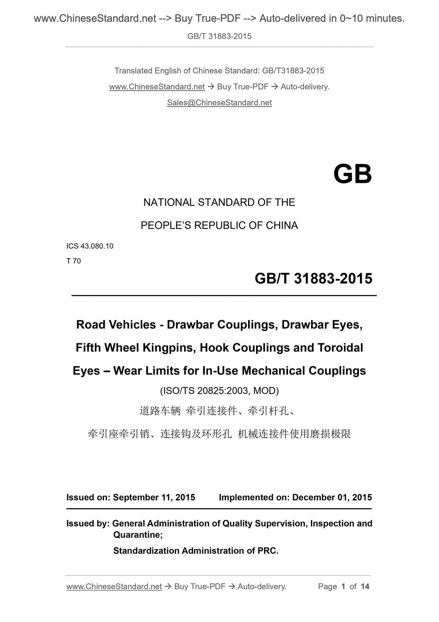
GB/T 31883-2015
NATIONAL STANDARD OF THE
PEOPLE’S REPUBLIC OF CHINA
ICS 43.080.10
T 70
Road Vehicles - Drawbar Couplings, Drawbar Eyes,
Fifth Wheel Kingpins, Hook Couplings and Toroidal
Eyes – Wear Limits for In-Use Mechanical Couplings
(ISO/TS 20825:2003, MOD)
ISSUED ON: SEPTEMBER 11, 2015
IMPLEMENTED ON: DECEMBER 01, 2015
Issued by: General Administration of Quality Supervision, Inspection and
Quarantine;
Standardization Administration of PRC.
Table of Contents
Foreword ... 3
1 Scope ... 4
2 Normative References ... 4
3 Inspection of Parts Wear ... 5
4 Wear Limit Size of Parts ... 9
Appendix A (Normative) Specified Size, Use Limit Size and Allowable Wear
Extent of Mechanical Couplings ... 12
Road Vehicles - Drawbar Couplings, Drawbar Eyes,
Fifth Wheel Kingpins, Hook Couplings and Toroidal
Eyes - Wear Limits for In-Use Mechanical Couplings
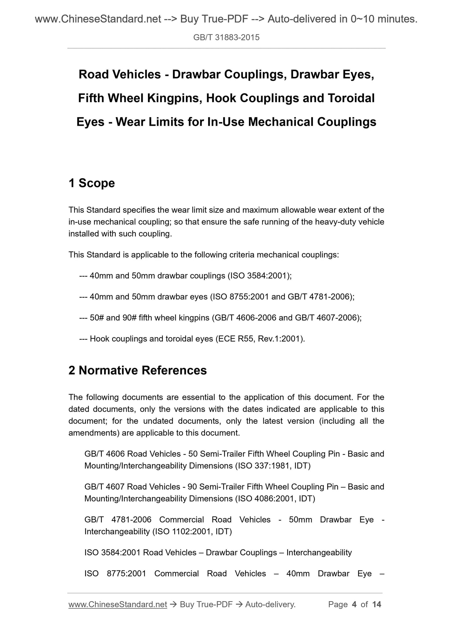
1 Scope
This Standard specifies the wear limit size and maximum allowable wear extent of the
in-use mechanical coupling; so that ensure the safe running of the heavy-duty vehicle
installed with such coupling.
This Standard is applicable to the following criteria mechanical couplings:
--- 40mm and 50mm drawbar couplings (ISO 3584:2001);
--- 40mm and 50mm drawbar eyes (ISO 8755:2001 and GB/T 4781-2006);
--- 50# and 90# fifth wheel kingpins (GB/T 4606-2006 and GB/T 4607-2006);
--- Hook couplings and toroidal eyes (ECE R55, Rev.1:2001).
2 Normative References
The following documents are essential to the application of this document. For the
dated documents, only the versions with the dates indicated are applicable to this
document; for the undated documents, only the latest version (including all the
amendments) are applicable to this document.
GB/T 4606 Road Vehicles - 50 Semi-Trailer Fifth Wheel Coupling Pin - Basic and
Mounting/Interchangeability Dimensions (ISO 337:1981, IDT)
GB/T 4607 Road Vehicles - 90 Semi-Trailer Fifth Wheel Coupling Pin – Basic and
Mounting/Interchangeability Dimensions (ISO 4086:2001, IDT)
GB/T 4781-2006 Commercial Road Vehicles - 50mm Drawbar Eye -
Interchangeability (ISO 1102:2001, IDT)
ISO 3584:2001 Road Vehicles – Drawbar Couplings – Interchangeability
ISO 8775:2001 Commercial Road Vehicles – 40mm Drawbar Eye –
Interchangeability
ECE R55, Rev.1:2001 Revision 1: 2001 – Uniform Provisions Concerning the
Approval of Mechanical Coupling Components of Combinations of Vehicles
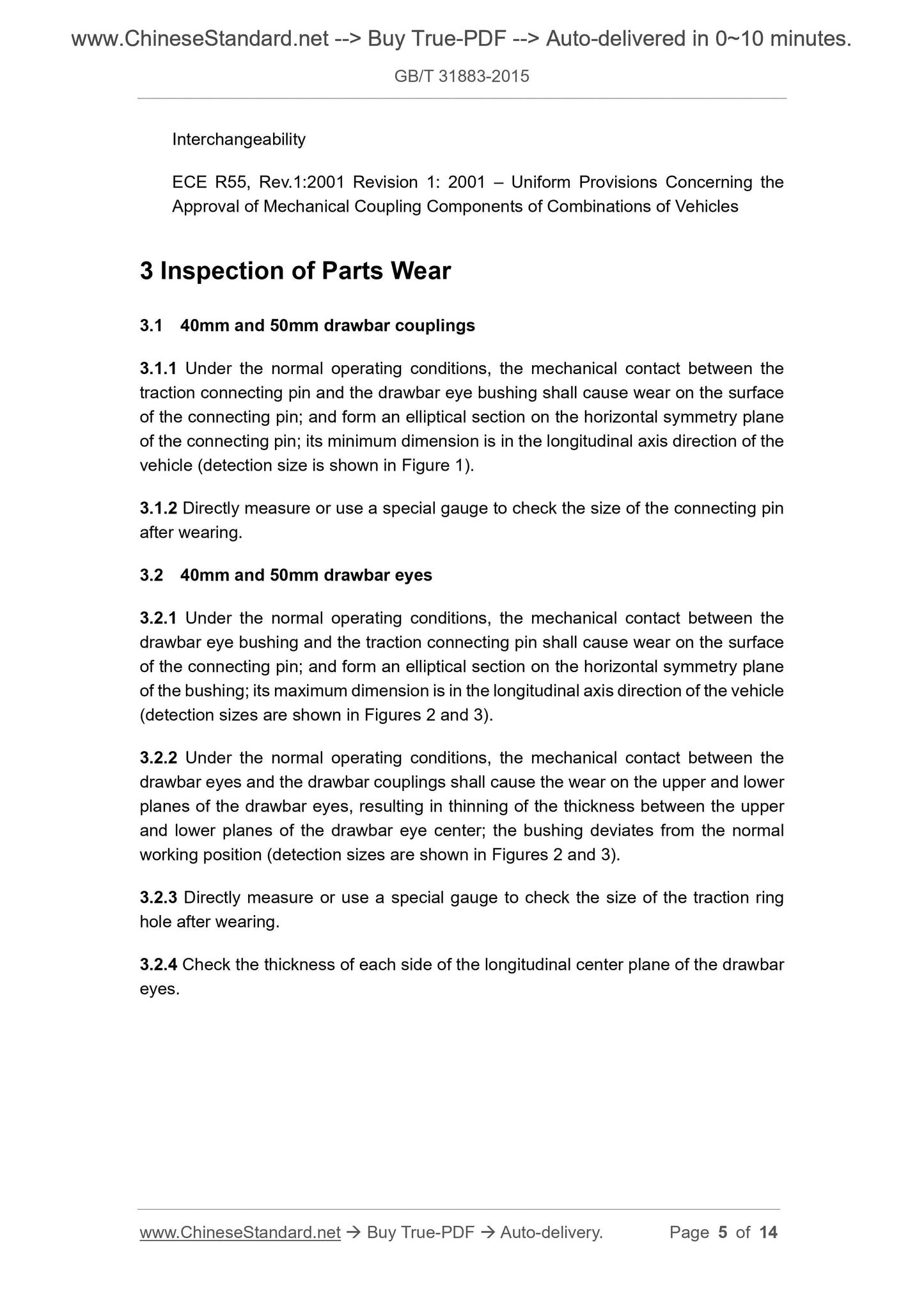
3 Inspection of Parts Wear
3.1 40mm and 50mm drawbar couplings
3.1.1 Under the normal operating conditions, the mechanical contact between the
traction connecting pin and the drawbar eye bushing shall cause wear on the surface
of the connecting pin; and form an elliptical section on the horizontal symmetry plane
of the connecting pin; its minimum dimension is in the longitudinal axis direction of the
vehicle (detection size is shown in Figure 1).
3.1.2 Directly measure or use a special gauge to check the size of the connecting pin
after wearing.
3.2 40mm and 50mm drawbar eyes
3.2.1 Under the normal operating conditions, the mechanical contact between the
drawbar eye bushing and the traction connecting pin shall cause wear on the surface
of the connecting pin; and form an elliptical section on the horizontal symmetry plane
of the bushing; its maximum dimension is in the longitudinal axis direction of the vehicle
(detection sizes are shown in Figures 2 and 3).
3.2.2 Under the normal operating conditions, the mechanical contact between the
drawbar eyes and the drawbar couplings shall cause the wear on the upper and lower
planes of the drawbar eyes, resulting in thinning of the thickness between the upper
and lower planes of the drawbar eye center; the bushing deviates from the normal
working position (detection sizes are shown in Figures 2 and 3).
3.2.3 Directly measure or use a special gauge to check the size of the traction ring
hole after wearing.
3.2.4 Check the thickness of each side of the longitudinal center plane of the drawbar
eyes.
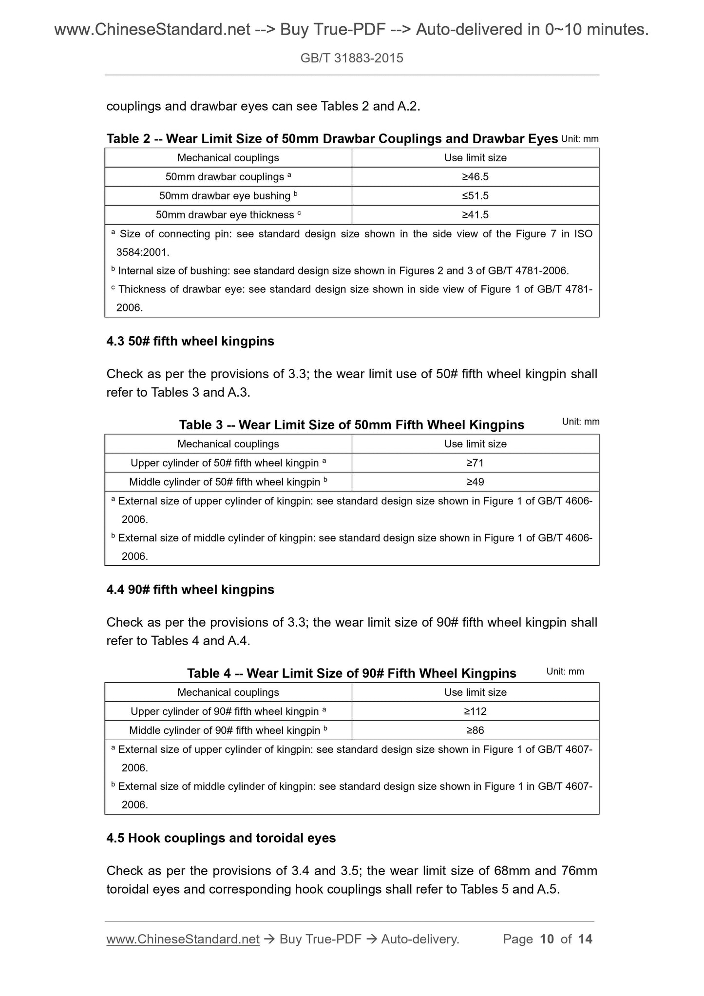
couplings and drawbar eyes can see Tables 2 and A.2.
Table 2 -- Wear Limit Size of 50mm Drawbar Couplings and Drawbar Eyes
Mechanical couplings Use limit size
50mm drawbar couplings a ≥46.5
50mm drawbar eye bushing b ≤51.5
50mm drawbar eye thickness c ≥41.5
a Size of connecting pin: see standard design size shown in the side view of the Figure 7 in ISO
3584:2001.
b Internal size of bushing: see standard design size shown in Figures 2 and 3 of GB/T 4781-2006.
c Thickness of drawbar eye: see standard design size shown in side view of Figure 1 of GB/T 4781-
2006.
4.3 50# fifth wheel kingpins
Check as per the provisions of 3.3; the wear limit use of 50# fifth wheel kingpin shall
refer to Tables 3 and A.3.
Table 3 -- Wear Limit Size of 50mm Fifth Wheel Kingpins
Mechanical couplings Use limit size
Upper cylinder of 50# fifth wheel kingpin a ≥71
Middle cylinder of 50# fifth wheel kingpin b ≥49
a External size of upper cylinder of kingpin: see standard design size shown in Figure 1 of GB/T 4606-
2006.
b External size of middle cylinder of kingpin: see standard design size shown in Figure 1 of GB/T 4606-
2006.
4.4 90# fifth wheel kingpins
Check as per the provisions of 3.3; the wear limit size of 90# fifth wheel kingpin shall
refer to Tables 4 and A.4.
Table 4 -- Wear Limit Size of 90# Fifth Wheel Kingpins
Mechanical couplings Use limit size
Upper cylinder of 90# fifth wheel kingpin a ≥112
Middle cylinder of 90# fifth wheel kingpin b ≥86
a External size of upper cylinder of kingpin: see standard design size shown in Figure 1 of GB/T 4607-
2006.
b External size of middle cylinder of kingpin: see standard design size shown in Figure 1 in GB/T 4607-
2006.
4.5 Hook couplings and toroidal eyes
Check as per the provisions of 3.4 and 3.5; the wear limit size of 68mm and 76mm
toroidal eyes and corresponding hook couplings shall refer to Tables 5 and A.5.
Unit: mm
Unit: mm
Unit: mm
Appendix A
(Normative)
Specified Size, Use Limit Size and Allowable Wear Extent of
Mechanical Couplings
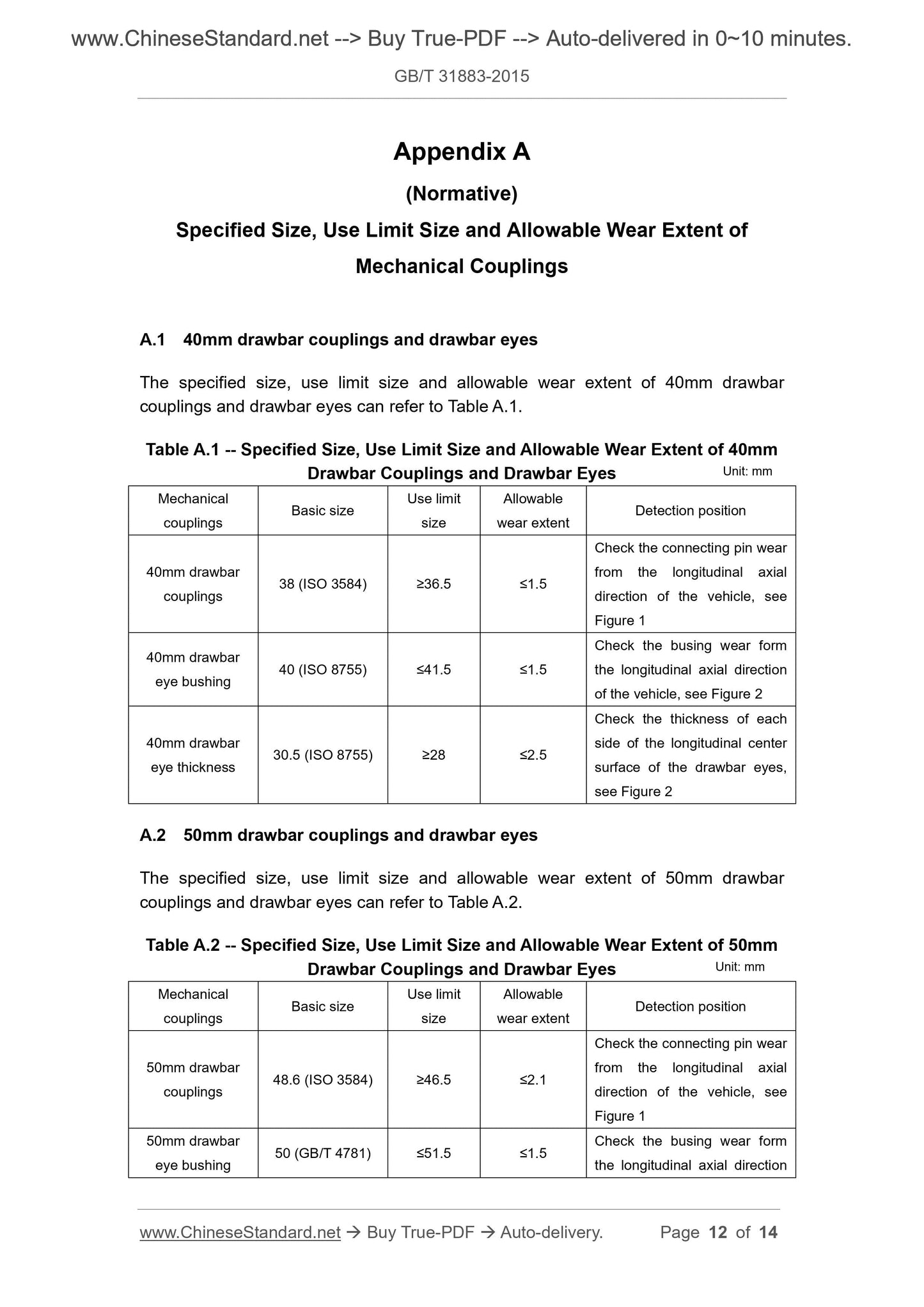
A.1 40mm drawbar couplings and drawbar eyes
The specified size, use limit size and allowable wear extent of 40mm drawbar
couplings and drawbar eyes can refer to Table A.1.
Table A.1 -- Specified Size, Use Limit Size and Allowable Wear Extent of 40mm
Drawbar Couplings and Drawbar Eyes
Mechanical
couplings Basic size
Use limit
size
Allowable
wear extent Detection position
40mm drawbar
couplings 38 (ISO 3584) ≥36.5 ≤1.5
Check the connecting pin wear
from the longitudinal axial
direction of the vehicle, see
Figure 1
40mm drawbar
eye bushing 40 (ISO 8755) ≤41.5 ≤1.5
Check the busing wear form
the longitudinal axial direction
of the vehicle, see Figure 2
40mm drawbar
eye thickness 30.5 (ISO 8755) ≥28 ≤2.5
Check the thickness of each
side of the longitudinal center
surface of the drawbar eyes,
see Figure 2
A.2 50mm drawbar couplings and drawbar eyes
The specified size, use limit size and allowable wear extent of 50mm drawbar
couplings and drawbar eyes can refer to Table A.2.
Table A.2 -- Specified Size, Use Limit Size and Allowable Wear Extent of 50mm
Drawbar Couplings and Drawbar Eyes
Mechanical
couplings Basic size
Use limit
size
Allowable
wear extent Detection position
50mm drawbar
couplings 48.6 (ISO 3584) ≥46.5 ≤2.1
Check the connecting pin wear
from the longitudinal axial
direction of the vehicle, see
Figure 1
50mm drawbar
eye bushing 50 (GB/T 4781) ≤51.5 ≤1.5
Check the busing wear form
the longitudinal axial direction
Unit: mm
Unit: mm
GB/T 31883-2015
NATIONAL STANDARD OF THE
PEOPLE’S REPUBLIC OF CHINA
ICS 43.080.10
T 70
Road Vehicles - Drawbar Couplings, Drawbar Eyes,
Fifth Wheel Kingpins, Hook Couplings and Toroidal
Eyes – Wear Limits for In-Use Mechanical Couplings
(ISO/TS 20825:2003, MOD)
ISSUED ON: SEPTEMBER 11, 2015
IMPLEMENTED ON: DECEMBER 01, 2015
Issued by: General Administration of Quality Supervision, Inspection and
Quarantine;
Standardization Administration of PRC.
Table of Contents
Foreword ... 3
1 Scope ... 4
2 Normative References ... 4
3 Inspection of Parts Wear ... 5
4 Wear Limit Size of Parts ... 9
Appendix A (Normative) Specified Size, Use Limit Size and Allowable Wear
Extent of Mechanical Couplings ... 12
Road Vehicles - Drawbar Couplings, Drawbar Eyes,
Fifth Wheel Kingpins, Hook Couplings and Toroidal
Eyes - Wear Limits for In-Use Mechanical Couplings
1 Scope
This Standard specifies the wear limit size and maximum allowable wear extent of the
in-use mechanical coupling; so that ensure the safe running of the heavy-duty vehicle
installed with such coupling.
This Standard is applicable to the following criteria mechanical couplings:
--- 40mm and 50mm drawbar couplings (ISO 3584:2001);
--- 40mm and 50mm drawbar eyes (ISO 8755:2001 and GB/T 4781-2006);
--- 50# and 90# fifth wheel kingpins (GB/T 4606-2006 and GB/T 4607-2006);
--- Hook couplings and toroidal eyes (ECE R55, Rev.1:2001).
2 Normative References
The following documents are essential to the application of this document. For the
dated documents, only the versions with the dates indicated are applicable to this
document; for the undated documents, only the latest version (including all the
amendments) are applicable to this document.
GB/T 4606 Road Vehicles - 50 Semi-Trailer Fifth Wheel Coupling Pin - Basic and
Mounting/Interchangeability Dimensions (ISO 337:1981, IDT)
GB/T 4607 Road Vehicles - 90 Semi-Trailer Fifth Wheel Coupling Pin – Basic and
Mounting/Interchangeability Dimensions (ISO 4086:2001, IDT)
GB/T 4781-2006 Commercial Road Vehicles - 50mm Drawbar Eye -
Interchangeability (ISO 1102:2001, IDT)
ISO 3584:2001 Road Vehicles – Drawbar Couplings – Interchangeability
ISO 8775:2001 Commercial Road Vehicles – 40mm Drawbar Eye –
Interchangeability
ECE R55, Rev.1:2001 Revision 1: 2001 – Uniform Provisions Concerning the
Approval of Mechanical Coupling Components of Combinations of Vehicles
3 Inspection of Parts Wear
3.1 40mm and 50mm drawbar couplings
3.1.1 Under the normal operating conditions, the mechanical contact between the
traction connecting pin and the drawbar eye bushing shall cause wear on the surface
of the connecting pin; and form an elliptical section on the horizontal symmetry plane
of the connecting pin; its minimum dimension is in the longitudinal axis direction of the
vehicle (detection size is shown in Figure 1).
3.1.2 Directly measure or use a special gauge to check the size of the connecting pin
after wearing.
3.2 40mm and 50mm drawbar eyes
3.2.1 Under the normal operating conditions, the mechanical contact between the
drawbar eye bushing and the traction connecting pin shall cause wear on the surface
of the connecting pin; and form an elliptical section on the horizontal symmetry plane
of the bushing; its maximum dimension is in the longitudinal axis direction of the vehicle
(detection sizes are shown in Figures 2 and 3).
3.2.2 Under the normal operating conditions, the mechanical contact between the
drawbar eyes and the drawbar couplings shall cause the wear on the upper and lower
planes of the drawbar eyes, resulting in thinning of the thickness between the upper
and lower planes of the drawbar eye center; the bushing deviates from the normal
working position (detection sizes are shown in Figures 2 and 3).
3.2.3 Directly measure or use a special gauge to check the size of the traction ring
hole after wearing.
3.2.4 Check the thickness of each side of the longitudinal center plane of the drawbar
eyes.
couplings and drawbar eyes can see Tables 2 and A.2.
Table 2 -- Wear Limit Size of 50mm Drawbar Couplings and Drawbar Eyes
Mechanical couplings Use limit size
50mm drawbar couplings a ≥46.5
50mm drawbar eye bushing b ≤51.5
50mm drawbar eye thickness c ≥41.5
a Size of connecting pin: see standard design size shown in the side view of the Figure 7 in ISO
3584:2001.
b Internal size of bushing: see standard design size shown in Figures 2 and 3 of GB/T 4781-2006.
c Thickness of drawbar eye: see standard design size shown in side view of Figure 1 of GB/T 4781-
2006.
4.3 50# fifth wheel kingpins
Check as per the provisions of 3.3; the wear limit use of 50# fifth wheel kingpin shall
refer to Tables 3 and A.3.
Table 3 -- Wear Limit Size of 50mm Fifth Wheel Kingpins
Mechanical couplings Use limit size
Upper cylinder of 50# fifth wheel kingpin a ≥71
Middle cylinder of 50# fifth wheel kingpin b ≥49
a External size of upper cylinder of kingpin: see standard design size shown in Figure 1 of GB/T 4606-
2006.
b External size of middle cylinder of kingpin: see standard design size shown in Figure 1 of GB/T 4606-
2006.
4.4 90# fifth wheel kingpins
Check as per the provisions of 3.3; the wear limit size of 90# fifth wheel kingpin shall
refer to Tables 4 and A.4.
Table 4 -- Wear Limit Size of 90# Fifth Wheel Kingpins
Mechanical couplings Use limit size
Upper cylinder of 90# fifth wheel kingpin a ≥112
Middle cylinder of 90# fifth wheel kingpin b ≥86
a External size of upper cylinder of kingpin: see standard design size shown in Figure 1 of GB/T 4607-
2006.
b External size of middle cylinder of kingpin: see standard design size shown in Figure 1 in GB/T 4607-
2006.
4.5 Hook couplings and toroidal eyes
Check as per the provisions of 3.4 and 3.5; the wear limit size of 68mm and 76mm
toroidal eyes and corresponding hook couplings shall refer to Tables 5 and A.5.
Unit: mm
Unit: mm
Unit: mm
Appendix A
(Normative)
Specified Size, Use Limit Size and Allowable Wear Extent of
Mechanical Couplings
A.1 40mm drawbar couplings and drawbar eyes
The specified size, use limit size and allowable wear extent of 40mm drawbar
couplings and drawbar eyes can refer to Table A.1.
Table A.1 -- Specified Size, Use Limit Size ...
View full details