GB/T 31838.7-2021 English PDF (GBT31838.7-2021)
Regular price
$255.00 USD
Regular price
Sale price
$255.00 USD
Unit price
/
per
Delivery: 3 seconds. Download true-PDF + Invoice.
Get QUOTATION in 1-minute: Click GB/T 31838.7-2021
Historical versions: GB/T 31838.7-2021
Preview True-PDF (Reload/Scroll if blank)
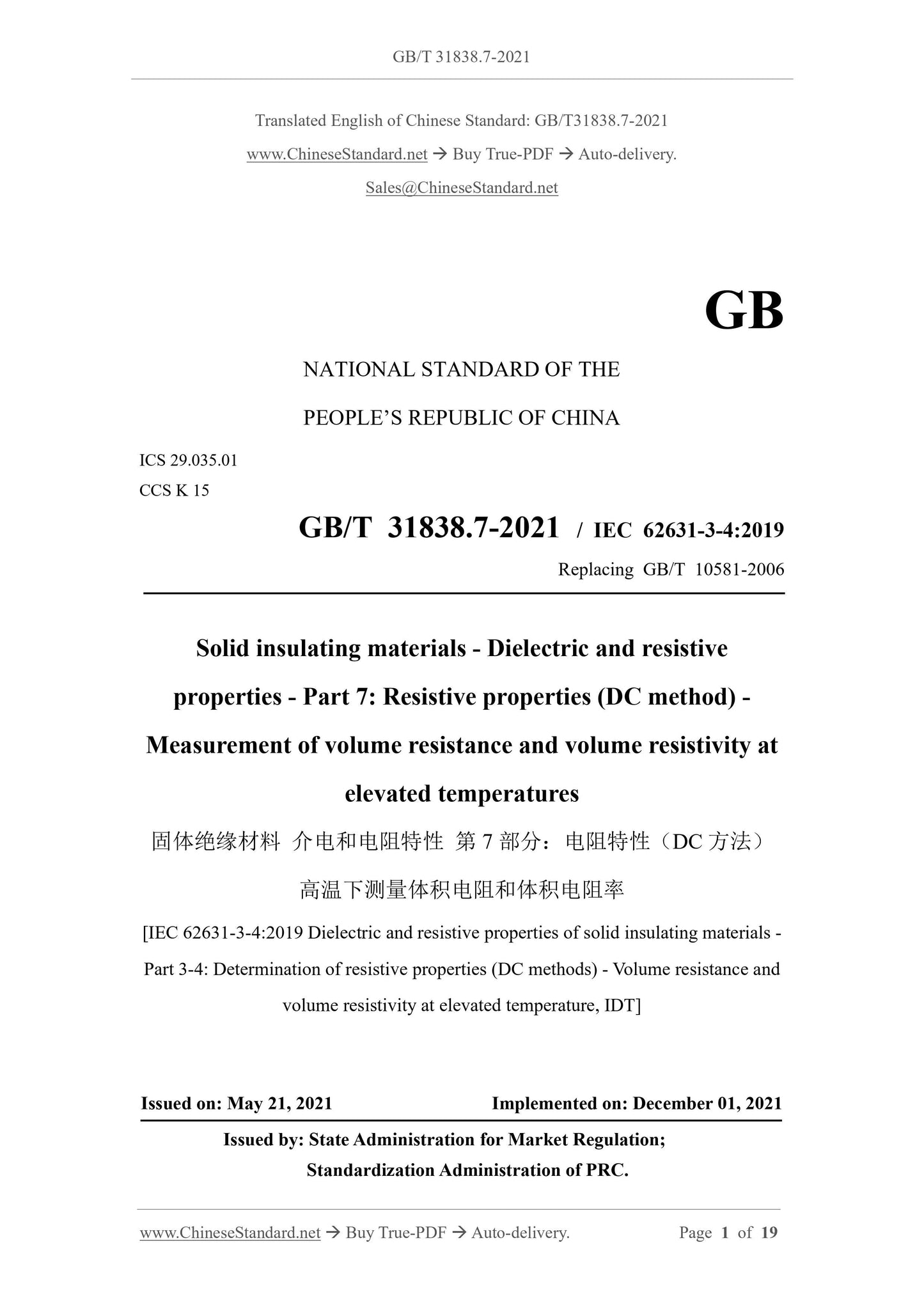
GB/T 31838.7-2021: Solid insulating materials - Dielecteric and resistive properties - Part 7: Resistive properties(DC method) - Measurement of volume resistance and volume resistivity at elevated temperatures
GB/T 31838.7-2021
NATIONAL STANDARD OF THE
PEOPLE’S REPUBLIC OF CHINA
ICS 29.035.01
CCS K 15
GB/T 31838.7-2021 / IEC 62631-3-4:2019
Replacing GB/T 10581-2006
Solid insulating materials - Dielectric and resistive
properties - Part 7: Resistive properties (DC method) -
Measurement of volume resistance and volume resistivity at
elevated temperatures
[IEC 62631-3-4:2019 Dielectric and resistive properties of solid insulating materials -
Part 3-4: Determination of resistive properties (DC methods) - Volume resistance and
volume resistivity at elevated temperature, IDT]
ISSUED ON: MAY 21, 2021
IMPLEMENTED ON: DECEMBER 01, 2021
Issued by: State Administration for Market Regulation;
Standardization Administration of PRC.
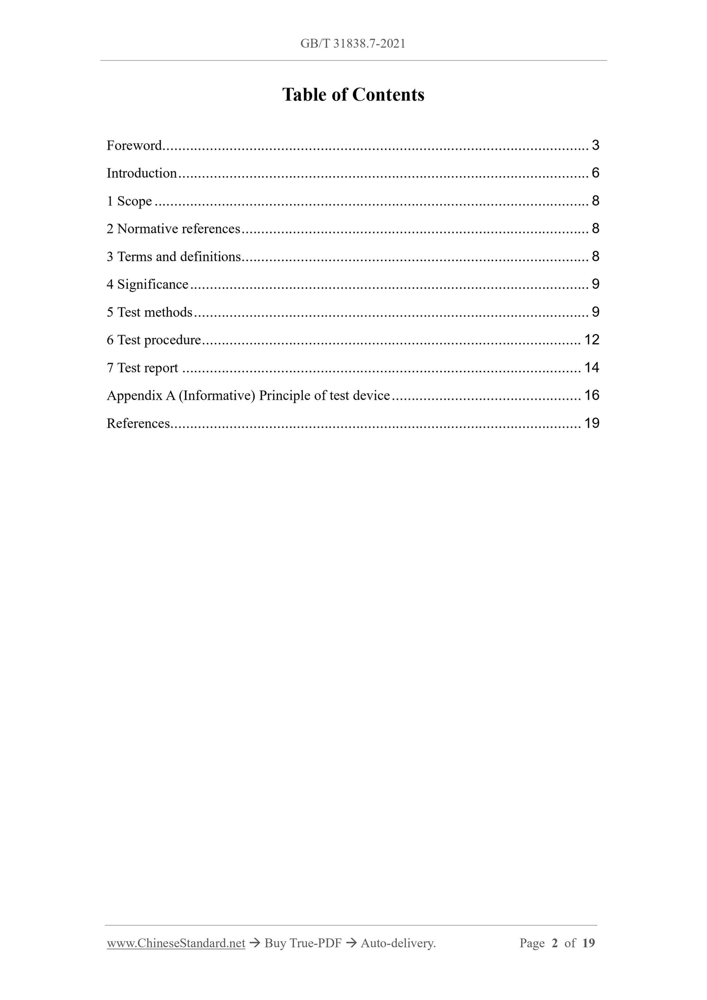
Table of Contents
Foreword ... 3
Introduction ... 6
1 Scope ... 8
2 Normative references ... 8
3 Terms and definitions... 8
4 Significance ... 9
5 Test methods ... 9
6 Test procedure ... 12
7 Test report ... 14
Appendix A (Informative) Principle of test device ... 16
References ... 19
Solid insulating materials - Dielectric and resistive
properties - Part 7: Resistive properties (DC method) -
Measurement of volume resistance and volume resistivity at
elevated temperatures
1 Scope
This document specifies the test methods for the volume resistance and volume
resistivity of insulating materials, under DC voltage and temperature not higher than
800 °C.
This document applies to high-temperature resistant mica plates, alumina ceramics and
other materials.
2 Normative references
The contents of the following documents constitute essential provisions of this
document through normative references in the text. Among them, for dated references,
only the version corresponding to the date applies to this document; for undated
references, the latest version (including all amendments) is applicable to this document.
GB/T 10580-2015 Standard conditions for the use of solid insulating materials
before and during testing (IEC 60212:2010, IDT)
IEC 62631-3-1 Dielectric and resistive properties of solid insulating materials - Part
3-1: Determination of resistive properties (DC methods) - Volume resistance and
volume resistivity - General methods
3 Terms and definitions
The following terms and definitions apply to this document.
The terms and definitions in ISO and IEC, which are used in this document, are
available at:
- ISO online browsing platform: https://www.iso.org/obp;
- IEC electronic encyclopedia: http://www.electropedia.org/.
3.1
Heating chamber
A device, that provides a high temperature to the specimen.
3.2
Volume resistance
The portion of insulation resistance, which is determined by volume conductivity.
Note: The unit of volume resistance is expressed in ohm (Ω).
3.3
Volume resistivity
Volume resistance, which is related to material volume.
Note 1: The unit of volume resistivity is expressed in ohm meter (Ω·m).
Note 2: For insulating materials, the volume resistivity is usually measured, by applying
electrodes on sheet specimens.
Note 3: According to IEC 60050-121, in electromagnetism, the "conductivity" is defined as
a scalar or tensor, whose product with the electric field strength in the medium is equal to
the current density; the "resistivity" is defined as "the reciprocal of conductivity, where there
is an inverse". When measured in this way, the volume resistivity is the average value of the
resistivity of possible inhomogeneities, within the volume in the measurement, including
the effects of possible polarization phenomena, at the electrodes.
4 Significance
Certain insulating materials are used at temperatures as high as 800 °C, such as mica
plates for supporting electrolytic aluminum cells, high-temperature crucibles, or
alumina ceramics for tubular resistance furnaces, etc.
Therefore, it is desirable for these materials to have the highest possible insulation
resistance. Measurements of volume resistance and volume resistivity can be used as
an aid, in selecting insulating materials for specific applications. Resistivity may vary
significantly with temperature. The conditions of use of electrical insulating materials
shall be understood, when designing products.
5 Test methods
5.1 Overview
The test methods, which are specified in this document, are applicable to specific
which is perpendicular to the surface of the specimen, OR on the side of the backing
plate, which is parallel to the surface of the specimen. If the thermocouple is installed
in the electrode's backing plate, the wire and the thermocouple shall be well insulated;
otherwise, the thermocouple shall be disconnected or removed, during measurement.
5.3.5 Special precautions during measurement
Errors in current measurement may be caused by the current measurement device,
which is shunted by resistances, between the protection terminal and the protection
system. In order to ensure the good operation of the equipment, measurements shall be
made, when the wires from the voltage source to the specimen are disconnected. In this
case, the device shall exhibit infinite resistance, within its sensitivity range. If a suitable
standard specimen of known value is available, it can be used to test the operation of
the equipment.
Because the insulation of the wiring is heated in the oven, it may reduce the volume
resistance, thereby affecting the measurement. The leakage resistance shall be measured
individually, at each temperature. There may be thermocouple potentials, between
different metals, so when the wiring metal and the electrode metal are different,
measurement errors may be caused. Using a short circuit, instead of the power supply,
the measured current can indicate the magnitude of the potential effect of the
thermocouple.
5.4 Calibration
The measuring equipment shall be calibrated, at room temperature, according to the
resistance value range of the measured volume.
Note: The commercial standard resistance has reached 100 TΩ.
6 Test procedure
6.1 Continuous heating (method A)
This method is suitable for the test, to quickly obtain the approximate relationship,
between the volume resistance and temperature of the specimen, in a wide temperature
range. It is only suitable for the comparison of materials, which have negligible
dielectric absorption, or similar materials. The specimen shall be installed tightly
between the electrode's backing plates, but not too tight, so as not to deform the
specimen when heated. The specified voltage is applied to the specimen. The heating
rate depends on the thickness of the material, which is not more than 5 K/min. As the
temperature increases, a sufficient number of resistance measurements shall be made,
to determine the relationship, between resistance and temperature.
6.2 Staged heating (method B)
This method is suitable for tests, that obtain a more accurate relationship, between
resistance and temperature, than continuous heating. It is also suitable for specimens,
which have dielectric absorption.
The specimen shall be installed tightly, between the electrode's backing plates, but not
too tight, so as not to deform the specimen when heated. Increase the temperature of
the specimen, from room temperature to the desired test temperature. Then gradually
increase from one test temperature to the next.
Note 1: The control method of the test chamber should ensure that, the temperature of the
elect...