1
/
of
12
PayPal, credit cards. Download editable-PDF and invoice in 1 second!
GB/T 31489.1-2015 English PDF (GB/T31489.1-2015)
Regular price
$480.00 USD
Regular price
Sale price
$480.00 USD
Unit price
/
per
Shipping calculated at checkout.
Couldn't load pickup availability
Delivery: 3 seconds. Download true-PDF + Invoice.
Get Quotation: Click GB/T 31489.1-2015 (Self-service in 1-minute)
Historical versions (Master-website): GB/T 31489.1-2015
Preview True-PDF (Reload/Scroll-down if blank)
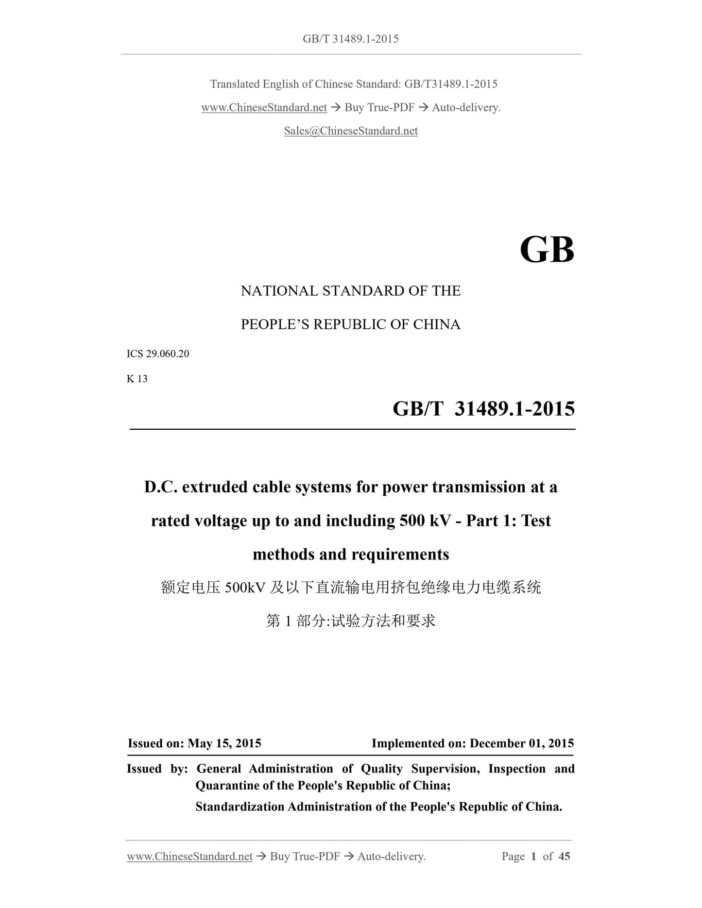
GB/T 31489.1-2015: D.C. extruded cable systems for power transmission at a rated voltage up to and including 500 kV - Part 1: Test methods and requirements
GB/T 31489.1-2015
GB
NATIONAL STANDARD OF THE
PEOPLE’S REPUBLIC OF CHINA
ICS 29.060.20
K 13
D.C. extruded cable systems for power transmission at a
rated voltage up to and including 500 kV - Part 1: Test
methods and requirements
ISSUED ON: MAY 15, 2015
IMPLEMENTED ON: DECEMBER 01, 2015
Issued by: General Administration of Quality Supervision, Inspection and
Quarantine of the People's Republic of China;
Standardization Administration of the People's Republic of China.
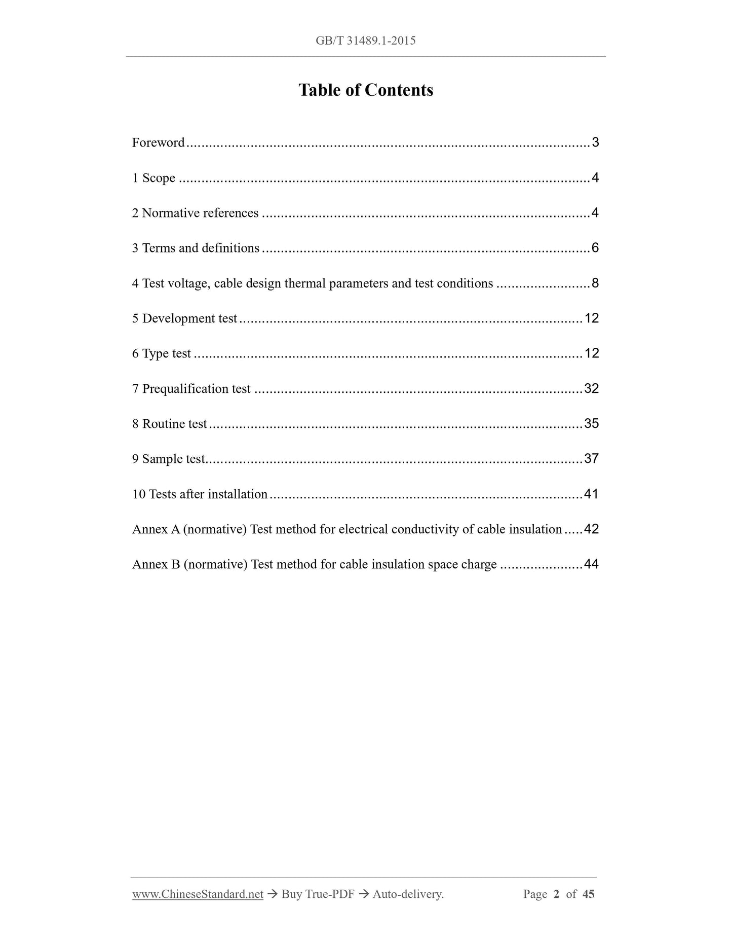
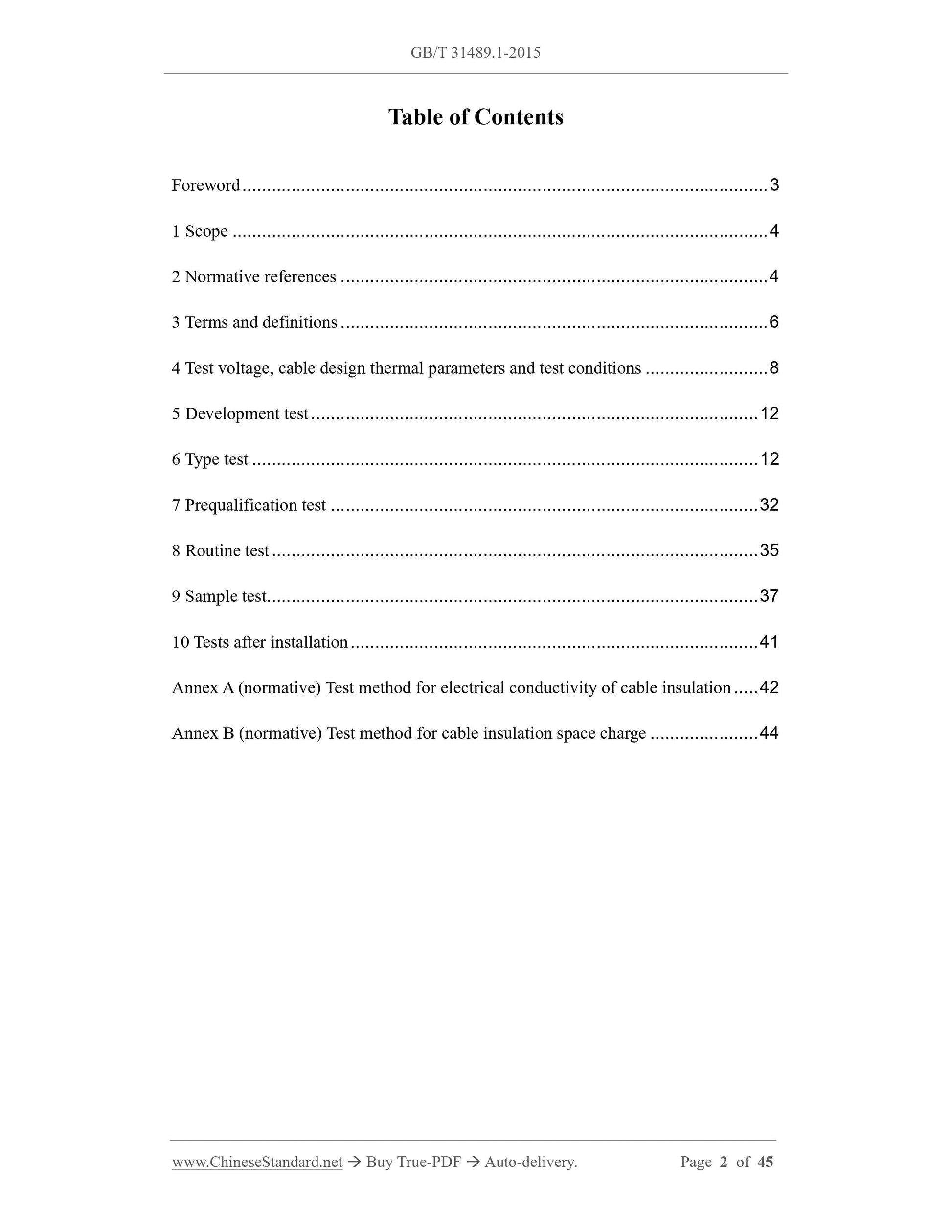
Table of Contents
Foreword ... 3
1 Scope ... 4
2 Normative references ... 4
3 Terms and definitions ... 6
4 Test voltage, cable design thermal parameters and test conditions ... 8
5 Development test ... 12
6 Type test ... 12
7 Prequalification test ... 32
8 Routine test ... 35
9 Sample test... 37
10 Tests after installation ... 41
Annex A (normative) Test method for electrical conductivity of cable insulation ... 42
Annex B (normative) Test method for cable insulation space charge ... 44
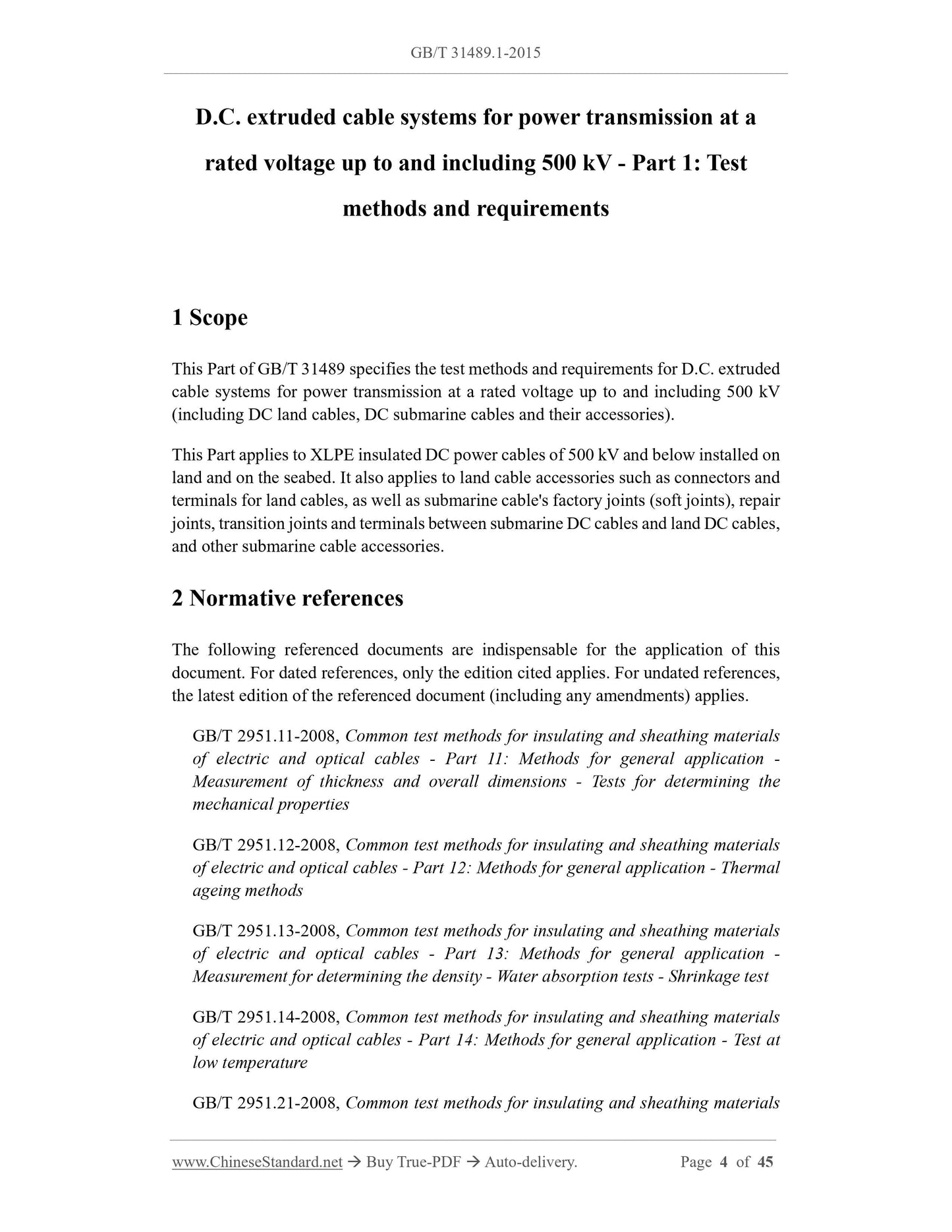
D.C. extruded cable systems for power transmission at a
rated voltage up to and including 500 kV - Part 1: Test
methods and requirements
1 Scope
This Part of GB/T 31489 specifies the test methods and requirements for D.C. extruded
cable systems for power transmission at a rated voltage up to and including 500 kV
(including DC land cables, DC submarine cables and their accessories).
This Part applies to XLPE insulated DC power cables of 500 kV and below installed on
land and on the seabed. It also applies to land cable accessories such as connectors and
terminals for land cables, as well as submarine cable's factory joints (soft joints), repair
joints, transition joints and terminals between submarine DC cables and land DC cables,
and other submarine cable accessories.
2 Normative references
The following referenced documents are indispensable for the application of this
document. For dated references, only the edition cited applies. For undated references,
the latest edition of the referenced document (including any amendments) applies.
GB/T 2951.11-2008, Common test methods for insulating and sheathing materials
of electric and optical cables - Part 11: Methods for general application -
Measurement of thickness and overall dimensions - Tests for determining the
mechanical properties
GB/T 2951.12-2008, Common test methods for insulating and sheathing materials
of electric and optical cables - Part 12: Methods for general application - Thermal
ageing methods
GB/T 2951.13-2008, Common test methods for insulating and sheathing materials
of electric and optical cables - Part 13: Methods for general application -
Measurement for determining the density - Water absorption tests - Shrinkage test
GB/T 2951.14-2008, Common test methods for insulating and sheathing materials
of electric and optical cables - Part 14: Methods for general application - Test at
low temperature
GB/T 2951.21-2008, Common test methods for insulating and sheathing materials
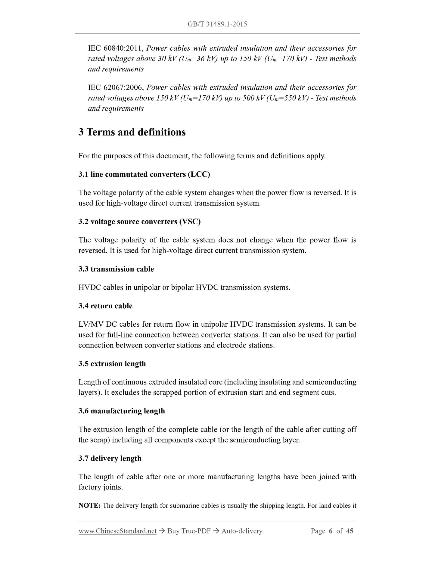
IEC 60840:2011, Power cables with extruded insulation and their accessories for
rated voltages above 30 kV (Um=36 kV) up to 150 kV (Um=170 kV) - Test methods
and requirements
IEC 62067:2006, Power cables with extruded insulation and their accessories for
rated voltages above 150 kV (Um=170 kV) up to 500 kV (Um=550 kV) - Test methods
and requirements
3 Terms and definitions
For the purposes of this document, the following terms and definitions apply.
3.1 line commutated converters (LCC)
The voltage polarity of the cable system changes when the power flow is reversed. It is
used for high-voltage direct current transmission system.
3.2 voltage source converters (VSC)
The voltage polarity of the cable system does not change when the power flow is
reversed. It is used for high-voltage direct current transmission system.
3.3 transmission cable
HVDC cables in unipolar or bipolar HVDC transmission systems.
3.4 return cable
LV/MV DC cables for return flow in unipolar HVDC transmission systems. It can be
used for full-line connection between converter stations. It can also be used for partial
connection between converter stations and electrode stations.
3.5 extrusion length
Length of continuous extruded insulated core (including insulating and semiconducting
layers). It excludes the scrapped portion of extrusion start and end segment cuts.
3.6 manufacturing length
The extrusion length of the complete cable (or the length of the cable after cutting off
the scrap) including all components except the semiconducting layer.
3.7 delivery length
The length of cable after one or more manufacturing lengths have been joined with
factory joints.
NOTE: The delivery length for submarine cables is usually the shipping length. For land cables it
is the complete cable length on the cable reel.
3.8 factory joint
A joint between extrusion length/manufacturing length under controlled factory
conditions.
3.9 repair joint
A joint between two complete cables.
3.10 field joint
A joint that is field installed between two complete cables of an existing cable system.
3.11 transition joint
A joint between two cables that are extruded insulation but differ in design (for example,
conductor cross-section or structure).
3.12 development tests
Tests performed during cable system development.
3.13 type tests
Tests on a type of cable system prior to supply on normal commercial principles, so as
to prove that the cable system has satisfactory performance in accordance with the
requirements of the intended use.
NOTE: Unless changes in the material, manufacturing process, and electrical stress design level of
the cable or accessory may change its performance characteristics, once the test is successfully
passed, it does not need to be repeated.
3.14 prequalification test
Tests on a type of cable system prior to supply on normal commercial principles, so as
to prove that the cable system has satisfactory long-term performance.
NOTE 1: Unless the material, manufacturing process and electrical stress design level of the cable
system are substantially changed, the prequalification test only needs to be carried out once.
NOTE 2: Substantial changes are defined as changes that adversely affect the cable system. If the
manufacturer declares that certain changes do not constitute substantial changes, detailed examples
including test verification are required.
3.15 routine tests
Tests carried out by the manufacturer on all manufactured lengths or attachments of
NOTE: If the polarity reversal cannot be achieved within 2min, the time for the polarity reversal
can be agreed upon by both parties.
4.3.7 Superimposed impulse voltage test (S/IMP)
Before the first impulse voltage is applied to the test object, the test object shall be
heated until the temperature of the conductor is not lower than Tc,max and the internal
temperature difference of the insulation is not lower than ΔTmax for at least 10 h. And
the test object has been subjected to U0 (corresponding polarity) for at least 10 h.
Maintain DC voltage. Superimpose the impulse voltage on the test object for 10
consecutive times. Then apply a DC voltage U0 of opposite polarity to the test object
under the same temperature conditions for at least 10 h. Maintain DC voltage.
Superimpose the impulse voltage on the test object for 10 consecutive times. The
interval between each impact shall not be less than 2min. Impulse voltage waveform
shall comply with the provisions of GB/T 3048.13-2007.
5 Development test
The manufacturer shall complete all analytical and development tests prior to
prequalification test. A development test shall at least include the following:
a) Evaluation of materials and processes used, typically including resistivity
evaluation, breakdown level and space charge measurements;
b) Distribution of electrical stresses within the insulation of cable systems under
typical installation and loading conditions;
c) Long-term stability assessment, including factory experiments to evaluate the
impact of various parameters on long-term performance, such as electrical stress,
temperature, environmental conditions;
d) Sensitivity to electrical stress distribution to expected changes in cable size,
material composition and process conditions (extrusion, post-extrusion handling).
6 Type test
6.1 Scope of type test approval
Type tests are also valid for other cable systems within the scope of this Standard if the
following conditions are met:
a) The design, material, manufacturing process and operating conditions of the cable
system are basically the same.
b) The operating voltage U0, UP1, UP2, S and UP2, O (URC, AC and URC, DC if it is a return
cable) is not higher than the tested cable system.
c) The mechanical stress applied by the mechanical pretreatment is not higher than
that of the tested cable system.
d) The maximum operating temperature Tc,max of the conductor is not higher than the
tested cable system.
e) The maximum temperature difference ΔTmax of the insulation layer is not higher
than the tested cable system.
f) The cross-sectional area of the conductor is not larger than the tested cable system.
g) The calculated value of the average field strength of the insulation (rated voltage
divided by the average thickness of the insulation) is not greater than the tested
cable system.
h) The Laplace electric field intensity at the cable conductor shield and insulation
shield calculated with the nominal size is not greater than that of the tested cable
system.
i) For cable systems that pass the LCC type test, as long as they pass the ±UP2,S
superimposed operating impulse voltage according to the provisions of 6.4.5.3,
the scope of approval can cover the VSC system, and vice versa.
Non-electrical type tests are not required for cables of all conductor cross-sections and
all voltage classes unless different materials and different manufacturing processes are
used (see 6.3). However, when the material outside the shielded core is different from
the tested cable system, the compatibility aging test of the finished cable section shall
be added, so as to verify the compatibility of the material.
6.2 Test object
All components (cables and accessories) of the cable system shall be type tested. Each
component can be tested in different test loops. These test loops shall contain all
relevant components of the cable system.
The test objects included in the typical test loop of the electrical type test are shown in
Figure 2. Accessory test objects shall include 0.5 m cables per side. Measure from cable
locations where no disassembly or disassembly has occurred due to mounting
accessories. The continuous cable length between the accessories in the test loop shall
not be less than 5 m. The length of continuous cable included in the test loop shall not
be less than 10 m.
Cable test objects shall include features that cause discontinuous connections in the
cable, such as metal connections between metal layers.
Specimens of land cables or submarine cables shall be mechanically pretreated before
insulating layer and protrusions greater than 0.125 mm into the semiconducting
shielding layer.
6.3.5 Combustion test
If the land cable adopts ST2 sheath, and the manufacturer declares that the design of the
cable meets the requirements of the combustion test, then the combustion test shall be
carried out on the finished cable specimen according to the provisions of GB/T
18380.12-2008, which shall meet the requirements.
6.3.6 Scraping test of non-metallic outer sheath
For land cable specimens after bending test in 6.4.3.1, the non-metallic outer sheath
shall be subjected to scraping test according to JB/T 10696.6-2007 and GB/T 2952.1-
2008, which shall meet the corresponding requirements.
6.3.7 Corrosion extension test (only applicable to aluminum sleeve)
For land cable specimens after bending test in 6.4.3.1, the aluminum sleeve shall be
subjected to corrosion expansion test according to JB/T 10696.5-2007 and GB/T
2952.1-2008, which shall meet the requirements.
6.3.8 Water penetration test
6.3.8.1 Water penetration test for land cables
When the land cable has a water-blocking structure, the water penetration test shall be
carried out. This test is applicable to the following cable constructions:
a) The barrier that can prevent water penetration longitudinally along the gap
between the outer surface of the insulation shield and the impermeable barrier;
b) The barrier that can prevent water penetration along the longitudinal direction of
the conductor.
The test device, sampling, test method and requirements shall comply with the
provisions of Annex I in GB/T 11017.1-2014.
6.3.8.2 Water penetration test for submarine cables
6.3.8.2.1 Overview
When the submarine cable has a water-blocking structure, the water penetration test
shall be carried out. Submarine cables shall be subjected to conductor water penetration
test, metal sheath water penetration test and factory joint radial water penetration test,
respectively.
The conductor water penetration test is to simulate the failure of the submarine cable in
the maximum water depth area, resulting in water intrusion from the conductor and
water penetration along the length direction. Cable specimens shall be subjected to
pretreatment as close to real installation conditions as possible. That is, specimens shall
be subjected to tensile bending test and thermal cycling test before the specimens are
immersed in water. Thermal cycle test is not required for immersion test. Because the
cable line will be out of service in the event of such a fault. The manufacturer shall
declare the maximum water penetration distance (d1) of the cable conductor after the
10-day water penetration test of the submarine cable.
The water penetration test under the metal sheath is to simulate the water penetration
under the metal sheath caused by the damage of the submarine cable in the nearshore
area. At this time, the effect ...
Share