1
/
of
12
PayPal, credit cards. Download editable-PDF and invoice in 1 second!
GB/T 31467.2-2015 English PDF (GBT31467.2-2015)
Regular price
$85.00 USD
Regular price
Sale price
$85.00 USD
Unit price
/
per
Shipping calculated at checkout.
Couldn't load pickup availability
Delivery: 3 seconds. Download true-PDF + Invoice.
Get Quotation: Click GB/T 31467.2-2015 (Self-service in 1-minute)
Historical versions (Master-website): GB/T 31467.2-2015
Preview True-PDF (Reload/Scroll-down if blank)
GB/T 31467.2-2015: [Replaced by GB/T 31467-2023] Lithium-ion traction battery pack and system for electric vehicles -- Part 2: Test specification for high energy applications
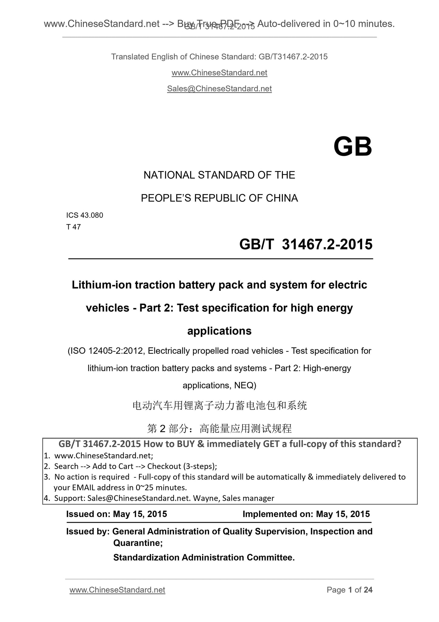
GB/T 31467.2-2015
Lithium-ion traction battery pack and system for electric vehicles - Part 2. Test specification for high energy applications
ICS 43.080
T47
National Standards of People's Republic of China
Electric vehicles using lithium-ion battery packs and systems
Part 2. Application of high energy test procedures
Part 2. Testspecificationforhighenergyapplications
(ISO 12405-2.2012, Electricalypropeledroadvehicles-
Part 2. High-energyapplications, NEQ)
Issued on. 2015-05-15
2015-05-15 implementation
Administration of Quality Supervision, Inspection and Quarantine of People's Republic of China
Standardization Administration of China released
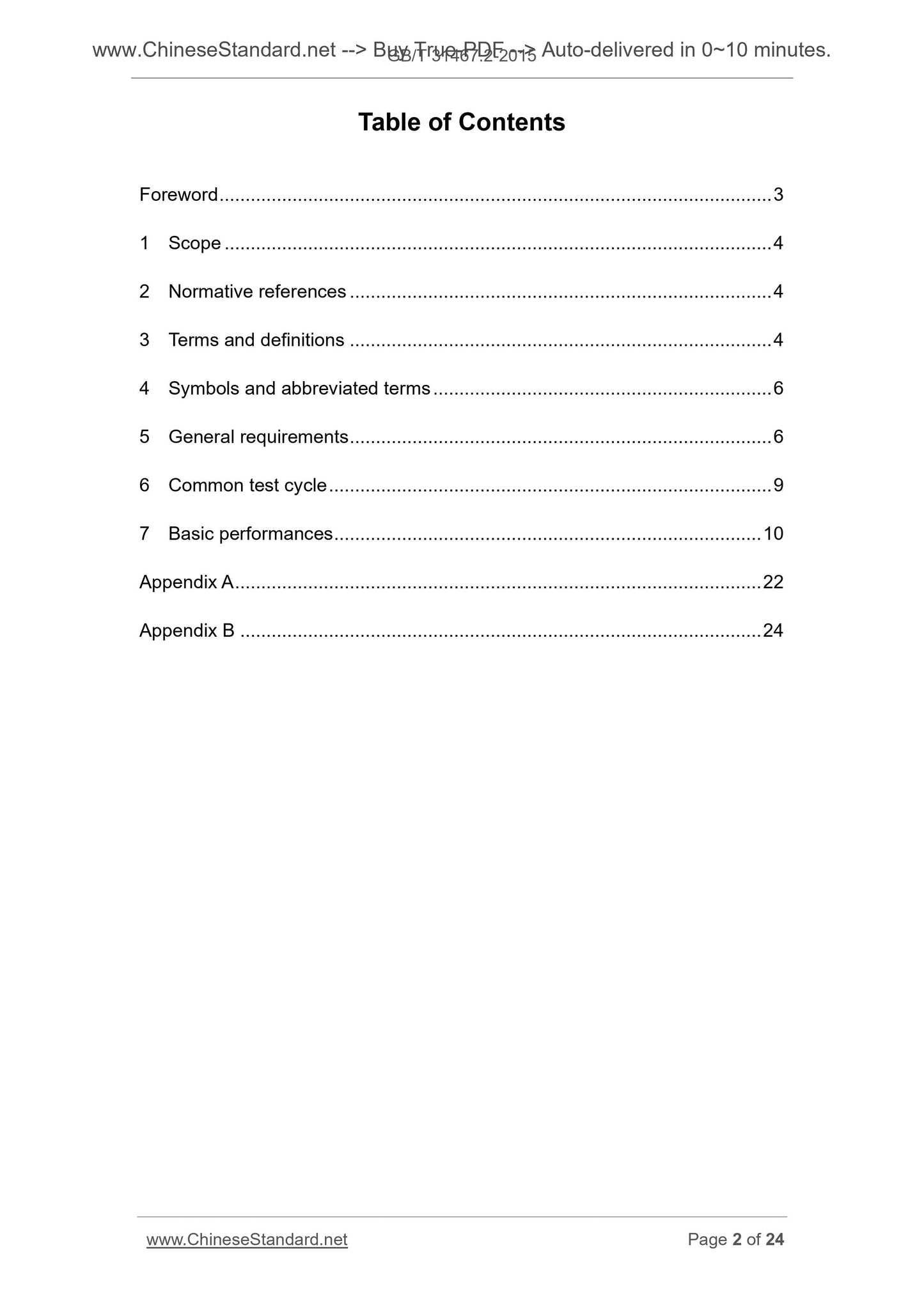
Table of Contents
Introduction Ⅲ
1 Scope 1
2 Normative references 1
3 Terms and definitions
4 Symbols and abbreviations 2
5 2 General Test Conditions
5.1 General Condition 2
5.2 accuracy requirements 3
5.3 Data recording and recording interval of 3
5.4 Test preparation 3
6 universal test cycle 4
6.1 Preconditioning cycle 4
6.2 standard cycle 4
7 Basic Performance 5
7.1 capacity and energy 5
7.2 power and resistance 7
7.3 No-load capacity loss 11
7.4 storage capacity loss 12
7.5 Energy Efficiency 12
Typical Structure Appendix A (informative) battery pack and battery system 14
Test Project Appendix B (normative) battery pack and battery system 16
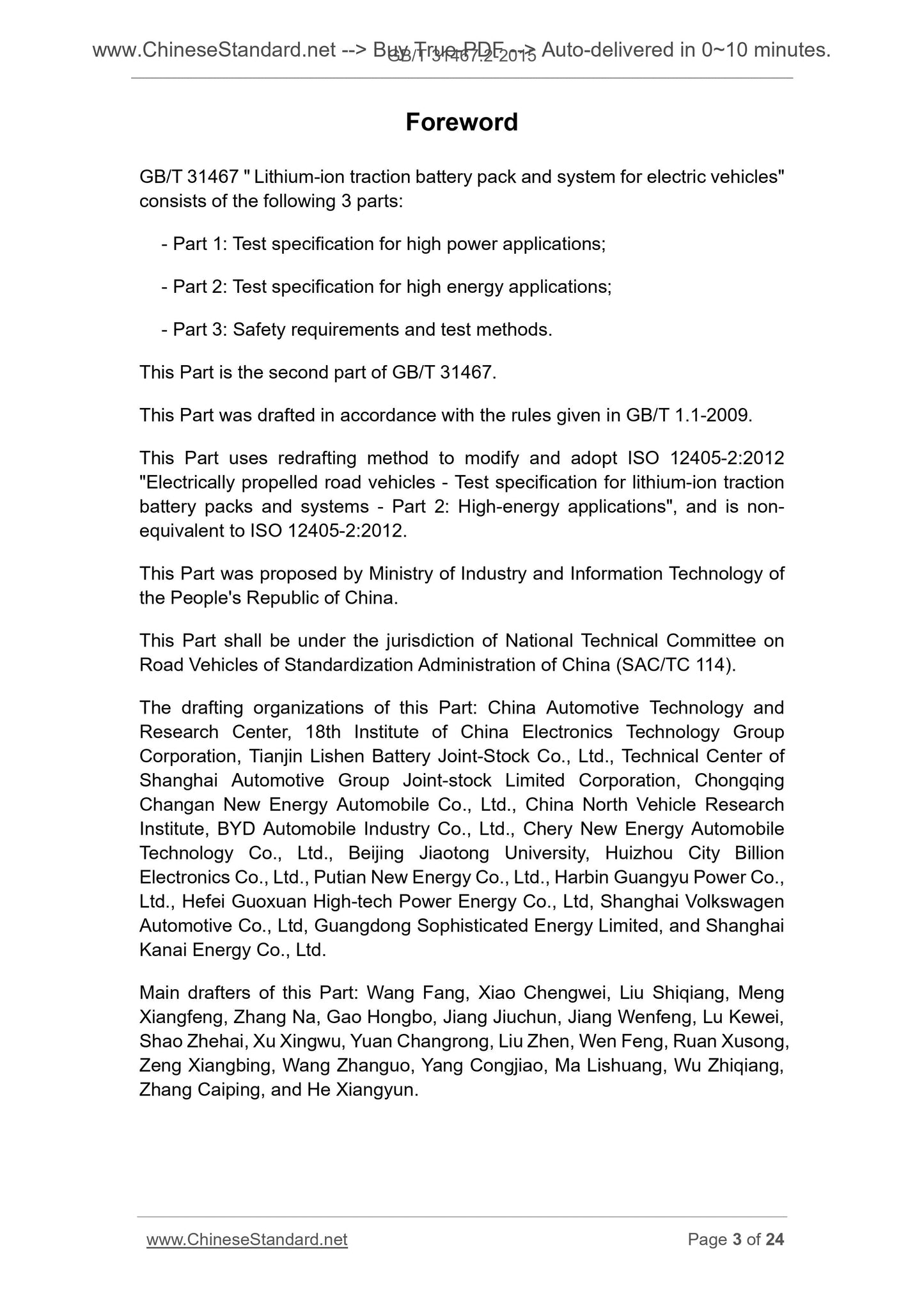
Foreword
GB/T 31467 "electric vehicles using lithium-ion battery packs and systems" is divided into the following three parts.
--- Part 1. High power applications, test procedures;
--- Part 2. Application of high energy test procedures;
--- Part 3. Safety requirements and test methods.
This section GB/T Part of 231,467.
This section drafted in accordance with GB/T 1.1-2009 given rules.
This section uses redrafted reference method ISO 12405-2.2012 "electric road vehicles lithium-ion battery pack and system testing
Procedures - Part 2. High energy applications, "compiled and ISO 12405-2.2012 is not equivalent degree of consistency.
This part is proposed by the Ministry of Industry and Information Technology of the People's Republic of China.
This part of the National Automotive Standardization Technical Committee (SAC/TC114) centralized.
This section drafted by. China Automotive Technology and Research Center, 18th Research Institute of China Electronics Technology Group Corporation, Tianjin Lishen Battery Unit
Parts Co., Shanghai Automotive Group Co., Ltd. Technical Center, Chongqing Changan New Energy Automobile Co., Ltd., China North Vehicle Research
The BYD Automobile Industry Co., Ltd., Chery Automobile New Energy Technology Co., Ltd., Beijing Jiaotong University, Huizhou City billion Electronic Co.,
Division Putian New Energy Co., Ltd., Harbin Guangyu Power Co., Ltd., Hefei, China Xuan Tech Power Energy Co., Ltd. and Shanghai
Volkswagen Co., Ltd., Guangdong Sophisticated Energy Ltd., Shanghai Kanai Energy Limited.
The main drafters of this section. Wang Fang, Xiaocheng Wei FOR THERMAL Meng Xiangfeng, Zhang Na, Gao Hongbo, Jiangjiu Chun, Jiang Wenfeng Lu Ke Wei, Shao Zhe Hai,
Xu Xing No, Yuan Changrong, Liu Zhen, Wenfeng, Ruanxu Song, Zeng Xiangbing, Wang Zhanguo, Cong Jiao Yang, Ma Li double, Wu Zhiqiang, Zhangcai Ping, and Xiang Yun.
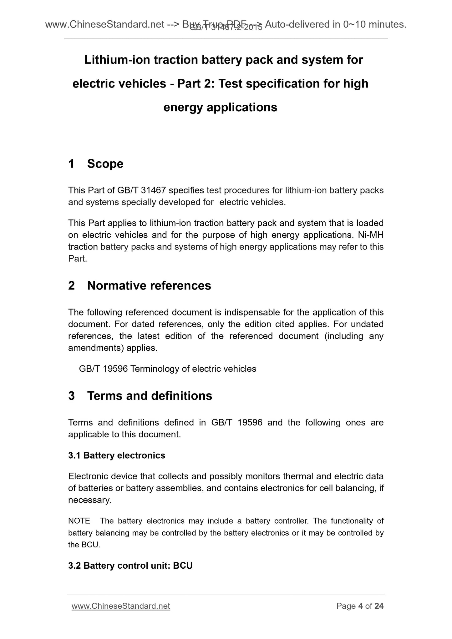
Electric vehicles using lithium-ion battery packs and systems
Part 2. Application of high energy test procedures
1 Scope
GB/T 31467 provisions of this part of the test method for electric vehicles high-energy lithium-ion battery pack and electric properties of the system.
This section applies to the load on the electric vehicle, mainly for the purpose of application of high-energy lithium-ion battery pack and battery system,
High energy applications for the purpose of nickel-hydrogen battery packs and systems can be implemented by reference.
2 Normative references
The following documents for the application of this document is essential. For dated references, only the dated version suitable for use herein
Member. For undated references, the latest edition (including any amendments) applies to this document.
GB/T 19596 Electric Vehicle Terminology
3 Terms and Definitions
GB/T 19596 and defined by the following terms and definitions apply to this document.
3.1
Battery electronic components batteryelectronics
Collected while monitoring the battery monomer or electronic device or module electrical and thermal data, when necessary, may include a battery monomer
Equilibrium electronic components.
Note. the electronic component may include monomers battery controller. Balanced between the cells can be controlled by a battery electronic components, or by the battery control
Control unit.
3.2
The battery control unit batterycontrolunit; BCU
Control, management, detecting or calculating the battery system and electric heat-related parameters, and provides a battery system controller and other vehicles pass
News of the electronic device.
3.3
Rated capacity ratedcapacityofbatterypack/system
Discharge capacity value under specified conditions as measured by the manufacturer claims the battery pack or system.
3.4
Battery pack batterypack
Typically include battery pack, battery management module (without BCU), battery box and the corresponding attachment, having obtained from an external power
And exporting electric power unit.
3.5
Battery system batterysystem
One or more of the battery pack and the corresponding accessory (management system, high-voltage circuit, low-voltage circuits, thermal management, and mechanical equipment assembly
Etc.) constituting the energy storage device.
3.6
High energy applications highenergyapplication
At room temperature or battery pack system maximum continuous output power (W) and its low in the ratio of 1C rate discharge energy (Wh) of
In device characteristics or application features 10.
3.7
High power applications highpowerapplication
Battery pack or system at room temperature for maximum permissible continuous output power (W) and the discharge energy (Wh) at 1C rate ratio of large
Than or equal to the device characteristics or application features 10.
3.8
High energy battery highenergytractionbattery
Designed for the application of high-energy power batteries.
3.9
High power batteries highpowertractionbattery
Designed to power high-power battery applications.
3.10
High-voltage highvoltage
Is greater than the maximum operating voltage 30Va.c. (rms) and less than or equal to 1000Va.c. (Rms), and less than, or greater than or equal 60Vd.c.
In 1500Vd.c. Voltage.
3.11
Low pressure lowvoltage
Maximum operating voltage is less than 30Va.c. (rms), or no greater than the voltage 60Vd.c..
4 Symbols and Abbreviations
The following symbols and abbreviations apply to this document.
nC. current rate, the discharge capacity is equal to n times 1h
I'max (SOC, T, t). a SOC, the test environment temperature T, the maximum allowable discharge current pulse duration t under
Imax (T). a test ambient temperature under the maximum allowable continuous discharge current
η. Efficiency
RT. room temperature (roomtemperature)
SOC. state of charge (stateofcharge)
5 General test conditions
5.1 General Conditions
5.1.1 except in certain specific test projects otherwise specified, testing at room temperature 25 ℃ ± 2 ℃, humidity of 15% to 90%
The next environment.
5.1.2 Test samples need to include the delivery of the necessary operating interface component files, as well as test equipment and required for connection, connector, plug
Head, including the cooling interfaces, battery packs and battery systems typical structure see Appendix A. Manufacturers need to provide a battery pack or system
Operating limits, to ensure the security of the entire testing process.
5.1.3 When the test target ambient temperature changes, before performing test specimens needed to complete the process of adaptation to the environment. to stand at a low temperature
Less than 24h; to stand at a high temperature of not less than 16h; or the cells and the target temperature difference between the ambient temperature does not exceed 2 ℃. testing sample
If you include a battery control unit, the acclimatization process needs to be turned off.
5.1.4 If the battery pack or the system for some reason (such as size or weight) is not suitable for certain tests, then the supply and demand sides of consensus
After the battery pack or subsystem can be used instead of the battery system as a test sample, in whole or part of the test, but as a sub-sample test
System should include all parts and vehicle-related requirements.
5.1.5 to adjust the SOC target value n% test methods are. charging according to the manufacturer's system or the battery pack is fully charged, quiet
Means 1h, constant current discharge of 1C (100-n)/100h. After each SOC adjustment, before the start of a new test requires a test sample was allowed to stand 1h.
5.1.6 during the test, in order to balance the internal reaction temperature and the battery pack or system, standing between some tests require certain steps
time. Standing during the low-voltage battery pack or system electronic control unit to work properly, such as batteries and other electronic components and BCU; Cooling
EC work in accordance with the manufacturer's specifications or BCU commands.
5.1.7 during the test discharge rate in accordance with the size of the provisions of this Part of charging and discharging a cut-off mechanism provided by the manufacturer.
However, these conditions should be before and after the reunification, such as charging and discharging mechanism mechanism cycle performance testing process should be the same as the provisions of other tests.
5.1.8 battery pack or the rated capacity of the system has important implications for the testing process. If the battery capacity is actually available (7.1.2.2)
And the absolute value of the difference between the battery rated capacity of more than 5% of the rated capacity, the test report to be clearly stated and actual available capacity
Instead of the rated capacity for charge and discharge current and the SOC calculation basis.
5.1.9 battery pack and battery system test items required, the test method reg number, test conditions and other information, see Appendix B.
5.1.10 battery discharge current sign is positive, the charging current sign is negative.
5.2 accuracy requirements
5.2.1 measuring instruments, meters of accuracy as follows.
--- Voltage measuring devices. not less than 0.5;
--- Current measuring devices. not less than 0.5;
--- Temperature measuring device. ± 0.5 ℃;
--- Time measuring means. ± 0.1%;
--- Sizing device. ± 0.1%;
--- Mass measuring device. ± 0.1%.
5.2.2 During the test, error control value (actual value) and the target value are as follows.
--- Voltage. ± 1%;
--- Current. ± 1%;
--- Temperature. ± 2 ℃.
5.3 Data recording and recording interval
Except in certain specific test project otherwise noted, each at least 1% recorded at intervals measured in anticipation of charging or discharging time
Test data, such as time, temperature, current and voltage.
5.4 Test preparation
5.4.1 battery packs ready
High pressure, low pressure and a cooling device and battery pack to bench test equipment is connected, turn on passive protection of the battery pack. According storage
Requirements and test procedures to test the battery pack manufacturers, test platform detection and control of the working status of the battery pack and operating parameters, and to ensure that the initiative
Protection on, you can disconnect the battery pack to achieve the main contactor if necessary. Cooling device operates according to the manufacturer's requirements. Power storage
Pool bag during the test, there is no exchange of information between the battery pack and the test platform, the battery pack is directly controlled by the parameter limits the test platform.
Test platform to detect the battery pack current, voltage, capacity, or energy and other parameters, and these test results and data as a basis for calculation.
5.4.2 Prepare battery system
High-voltage battery system, low pressure, the cooling device and BCU and test platforms to connected devices, turn on the battery system and is active
Protection. Test platform to ensure consistent test parameters and test conditions and code requirements, and to ensure that the battery system works in reasonable limits of
Within these limits by the BCU to a test platform by bus transfer. BCU control operating cooling device. BCU necessary program can
By the battery system manufacturer to make changes according to the test procedures. Active protection but also by the need to ensure that the test equipment platform, can, if necessary
Disconnect the battery system through the main contactor. System testing the battery, the battery system via bus communication and testing platform,
The battery condition parameters and operating limits real-time transmission to the test platform, and then control testing by the test platform based on the battery status and operating limits
process. Current, voltage, capacity or energy parameters such as test platform to detect the battery system, and as a result of the detection and calculation of these data
in accordance with. Upload battery system parameters are not as test results or test basis.
Quality and volume of the test sample 5.4.3
Measured by measuring the test sample dimensions, calculate the volume of the test sample, the unit L. Measuring the mass of the test sample with the instrument,
Unit kg. If the test sample contains the forced cooling system, measure or calculate the mass and volume, the cooling system should be included, such as
Cooling circuit and the like. If the cooling system uses a liquid cooling mode, the quality of the coolant should also be taken into account. If the test sample and the cooling system
Or other vehicle cooling systems integrated with the test sample and to consider only relevant portions of the mass and volume. When difficult to measure, can be prepared
Data and data supplied by the manufacturer of the test basis.
6 universal test cycle
6.1 Preconditioning cycle
6.1.1 before the official start of the test, the battery pack or...
Share