Skip to product information
1 of 10

PayPal, credit cards. Download editable-PDF and invoice in 1 second!

GB/T 30677-2014 English PDF (GBT30677-2014)

GB/T 30677-2014 English PDF (GBT30677-2014)

Regular price $150.00 USD
Regular price Sale price $150.00 USD
Sale Sold out
Shipping calculated at checkout.
Delivery: 3 seconds. Download true-PDF + Invoice.
Get QUOTATION in 1-minute: Click GB/T 30677-2014
Historical versions: GB/T 30677-2014
Preview True-PDF (Reload/Scroll if blank)

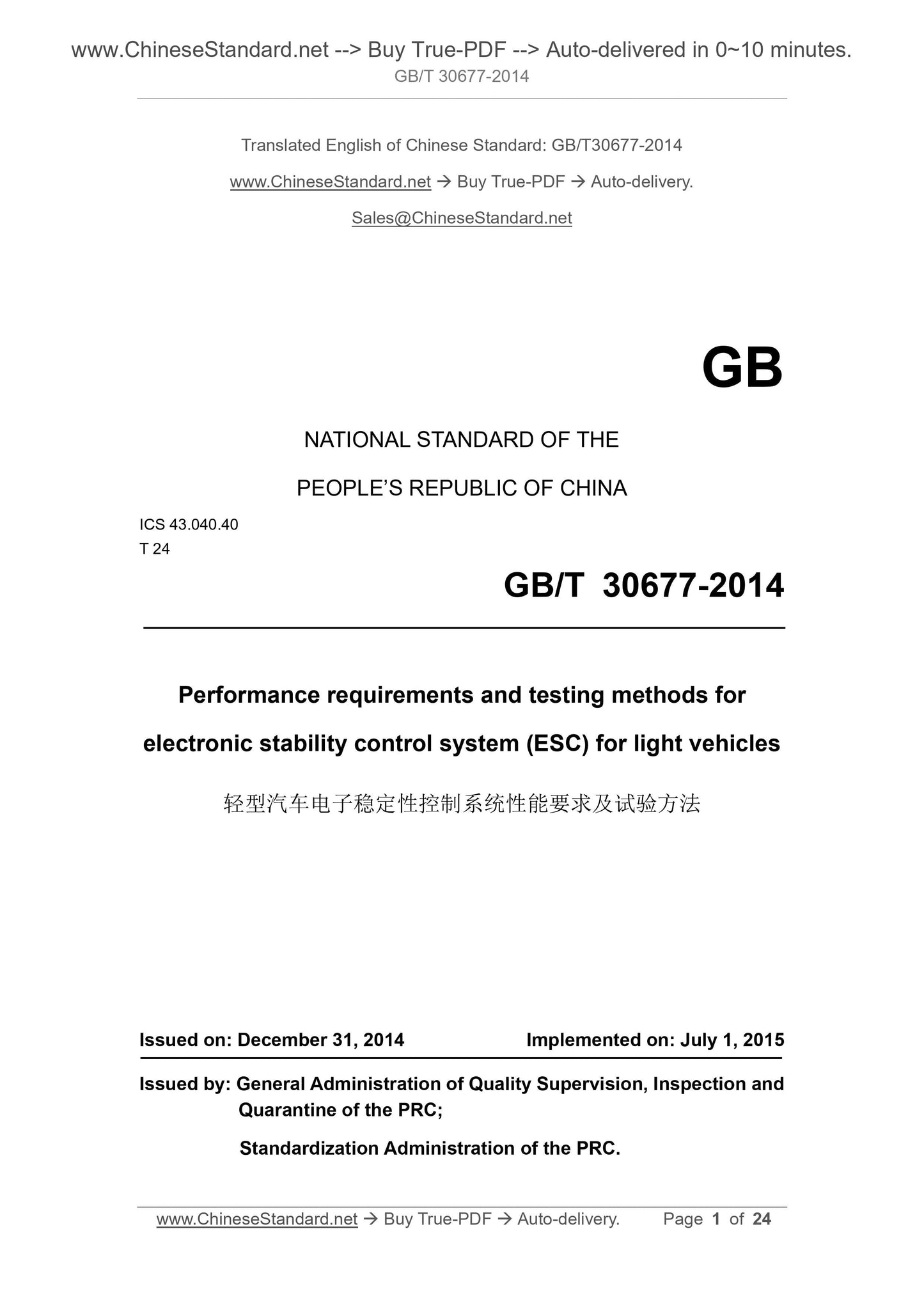
GB/T 30677-2014: Performance requirements and testing methods for electronic stability control system (ESC) for light vehicles
GB/T 30677-2014
GB
NATIONAL STANDARD OF THE
PEOPLE’S REPUBLIC OF CHINA
ICS 43.040.40
T 24
Performance requirements and testing methods for
electronic stability control system (ESC) for light vehicles
ISSUED ON. DECEMBER 31, 2014
IMPLEMENTED ON. JULY 1, 2015
Issued by. General Administration of Quality Supervision, Inspection and
Quarantine of the PRC;
Standardization Administration of the PRC.
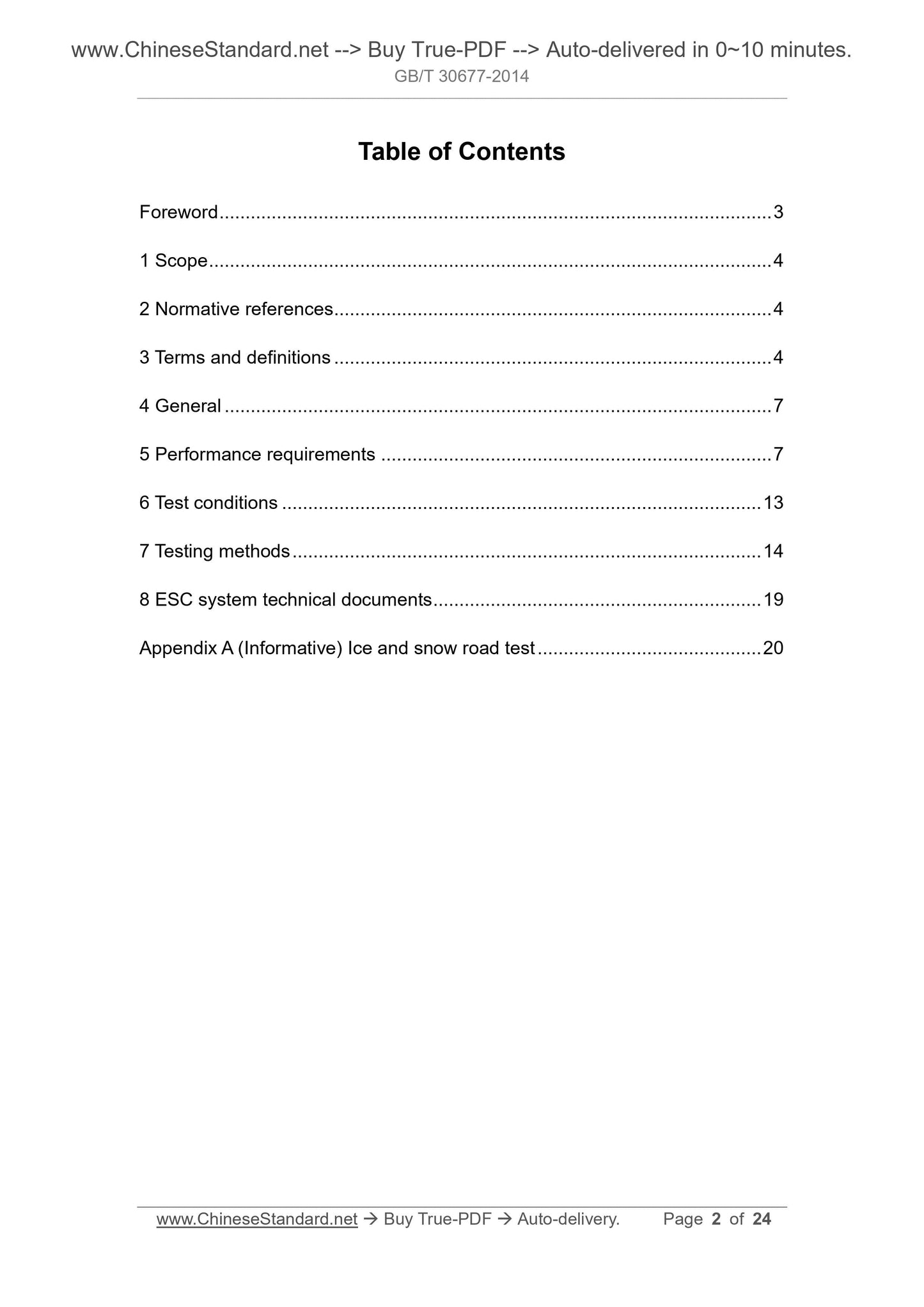
Table of Contents
Foreword ... 3 
1 Scope ... 4 
2 Normative references ... 4 
3 Terms and definitions ... 4 
4 General ... 7 
5 Performance requirements ... 7 
6 Test conditions ... 13 
7 Testing methods ... 14 
8 ESC system technical documents ... 19 
Appendix A (Informative) Ice and snow road test ... 20 
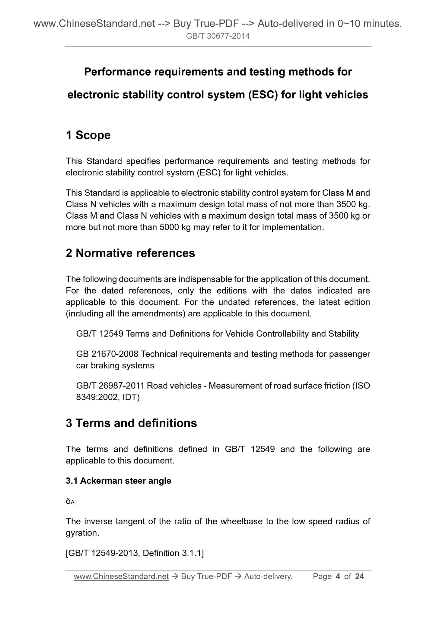
Performance requirements and testing methods for
electronic stability control system (ESC) for light vehicles
1 Scope
This Standard specifies performance requirements and testing methods for
electronic stability control system (ESC) for light vehicles.
This Standard is applicable to electronic stability control system for Class M and
Class N vehicles with a maximum design total mass of not more than 3500 kg.
Class M and Class N vehicles with a maximum design total mass of 3500 kg or
more but not more than 5000 kg may refer to it for implementation.
2 Normative references
The following documents are indispensable for the application of this document.
For the dated references, only the editions with the dates indicated are
applicable to this document. For the undated references, the latest edition
(including all the amendments) are applicable to this document.
GB/T 12549 Terms and Definitions for Vehicle Controllability and Stability
GB 21670-2008 Technical requirements and testing methods for passenger
car braking systems
GB/T 26987-2011 Road vehicles - Measurement of road surface friction (ISO
8349.2002, IDT)
3 Terms and definitions
The terms and definitions defined in GB/T 12549 and the following are
applicable to this document.
3.1 Ackerman steer angle
δA
The inverse tangent of the ratio of the wheelbase to the low speed radius of
gyration.
[GB/T 12549-2013, Definition 3.1.1]
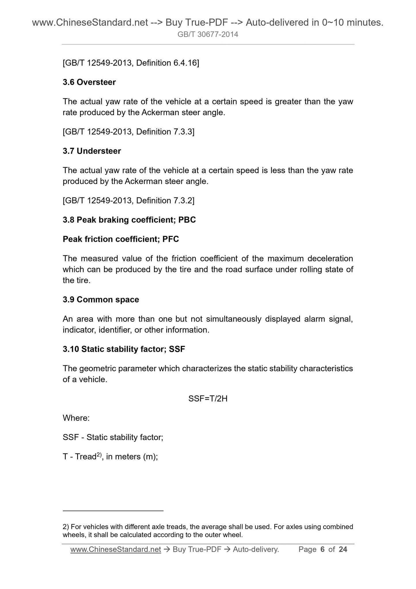
[GB/T 12549-2013, Definition 6.4.16]
3.6 Oversteer
The actual yaw rate of the vehicle at a certain speed is greater than the yaw
rate produced by the Ackerman steer angle.
[GB/T 12549-2013, Definition 7.3.3]
3.7 Understeer
The actual yaw rate of the vehicle at a certain speed is less than the yaw rate
produced by the Ackerman steer angle.
[GB/T 12549-2013, Definition 7.3.2]
3.8 Peak braking coefficient; PBC
Peak friction coefficient; PFC
The measured value of the friction coefficient of the maximum deceleration
which can be produced by the tire and the road surface under rolling state of
the tire.
3.9 Common space
An area with more than one but not simultaneously displayed alarm signal,
indicator, identifier, or other information.
3.10 Static stability factor; SSF
The geometric parameter which characterizes the static stability characteristics
of a vehicle.
SSF=T/2H
Where.
SSF - Static stability factor;
T - Tread2), in meters (m);
2) For vehicles with different axle treads, the average shall be used. For axles using combined
wheels, it shall be calculated according to the outer wheel.
mode which the driver selected in the previous travel, the ESC has more
than one control mode which can meet the requirements of 5.1.2 and 5.1.3;
then after the ignition system is restarted, the ESC shall be restored to the
initial default mode set by the manufacturer for the drive mode.
5.3.3 If the ESC control device is only to set the ESC to a control mode which
no longer satisfies the requirements of 5.1.1, 5.1.2, 5.1.3, and 5.1.4, it shall be
indicated by the identification symbol shown in Figure 3 or the word “ESC OFF”.
Figure 3 -- Identification symbol for ESC shutoff control
5.3.4 If the ESC control device can set the ESC to different control modes, and
at least one of the modes no longer satisfies the performance requirements of
5.1.1, 5.1.2, 5.1.3, and 5.1.4, it shall be indicated by the identification symbol
shown in Figure 2; and at a position close to this control mode, the word “OFF”
shall be marked.
For vehicles with ESC control mode controlled by a multi-function control device,
when the control device is in this mode, through the driver information display
system, it shall use the identification symbol specified in 5.3.3 or the word “ESC
OFF” to clearly display the control device being in this mode.
5.3.5 If the control device of other systems can also place the ESC in a mode
which no longer meets the performance requirements of 5.1.1, 5.1.2, 5.1.3, and
5.1.4, it is not necessary to use the method in 5.3.3 to indicate it.
5.4 ESC shutoff signaling device
5.4.1 If the manufacturer, in accordance with 5.3, installs a control device to
shut off or reduce the performance of the ESC, the signaling device
requirements of 5.4.2~5.4.5 shall be met, to alert the driver when the ESC
function is degraded. This requirement does not apply to the mode selected by
the driver as described in 5.3.2.b).
5.4.2 If the vehicle manufacturer sets a control mode in which the ESC does
not meet the requirements of 5.1.1, 5.1.2, 5.1.3, and 5.1.4, an alarm device
shall be set to indicate when the ESC is in this control mode.
5.4.3 The signaling device shall meet the following requirements.
6 Test conditions
6.1 Environmental conditions
6.1.1 The ambient temperature is 0 °C~45 °C.
6.1.2 For vehicles with a static stability factor greater than 1.25, the maximum
wind speed is not greater than 10 m/s. For vehicles with a static stability factor
not greater than 1.25, the maximum wind speed is not greater than 5 m/s.
6.2 Test road surface
6.2.1 The test shall be carried out on a dry, even, solid road surface. Undulating
and uneven road surface (for example, there is a sinking phenomenon or a
large crack) is not suitable for testing.
6.2.2 Unless otherwise specified, the peak braking coefficient (PBC) of the test
road surface shall, according to the provisions of Clause 6 of GB/T 26987-2011,
be determined on the dry road surface. Its value shall not be less than 0.9. As
an alternative, according to the method of 5.6.4 in GB 21670-2008, it can also
be determined.
6.2.3 The test road surface shall be a single slope. The slope shall be no more
than 1%.
6.3 Vehicle state
6.3.1 All tests shall be performed under the normal working state of the ESC.
6.3.2 The vehicle is in the state of complete vehicle curb weight. The total mass
of internal loading is 168 kg, including the test driver, test equipment, and
necessary counterweight sandbags. The counterweight sandbag is determined
according to the difference between the mass of test driver and test equipment
and the specified internal loading total mass (168 kg). It shall normally be placed
on the floor at the rear of the front passenger seat. If necessary, it can also be
placed in the foot area of the front passenger. All counterweight sandbags shall
be placed reliably, to avoid movement during the test.
6.3.3 The tire pressure shall be the recommended cold tire inflation pressure
by the vehicle manufacturer (see vehicle sign or tire inflation pressure
identification). If necessary, the inner tube can be installed to prevent the tire
from being detached.
6.3.4 To ensure the test safety, an anti-tur...
View full details