GB/T 30195-2023 English PDF (GBT30195-2023)
Regular price
$245.00 USD
Regular price
Sale price
$245.00 USD
Unit price
/
per
Delivery: 3 seconds. Download true-PDF + Invoice.
Get QUOTATION in 1-minute: Click GB/T 30195-2023
Historical versions: GB/T 30195-2023
Preview True-PDF (Reload/Scroll if blank)
GB/T 30195-2023: Test method for measuring impact resistance of passenger car tyres -- Pendulum striker method
GB/T 30195-2023
GB
NATIONAL STANDARD OF THE
PEOPLE’S REPUBLIC OF CHINA
ICS 83.160.10
CCS G 41
Replacing GB/T 30195-2013
Test method for measuring impact resistance of passenger
car tyres - Pendulum striker method
ISSUED ON: MAY 23, 2023
IMPLEMENTED ON: DECEMBER 01, 2023
Issued by: State Administration for Market Regulation;
Standardization Administration of the People's Republic of China.
Table of Contents
Foreword ... 3
1 Scope ... 5
2 Normative references ... 5
3 Terms and definitions ... 5
4 Test equipment and accuracy ... 7
5 Test conditions and test preparation ... 8
6 Test procedures ... 8
7 Data processing ... 10
8 Test report ... 11
Annex A (informative) Schematic diagram of test equipment ... 13
Annex B (normative) Technical requirements for strikers ... 17
Annex C (informative) Bulge gauge ... 20
Test method for measuring impact resistance of passenger
car tyres - Pendulum striker method
1 Scope
This document describes the test equipment and accuracy, test conditions and test
preparation, test procedures, data processing, and test reports for testing tire impact
resistance using the pendulum method.
This document is applicable to testing the impact resistance of pneumatic tires of new
passenger car.
2 Normative references
The following referenced documents are indispensable for the application of this
document. For dated references, only the edition cited applies. For undated references,
the latest edition of the referenced document (including any amendments) applies.
GB/T 3487, Rims for passenger car
GB/T 6326, Tyre terms and definitions
3 Terms and definitions
For the purposes of this document, the terms and definitions defined in GB/T 6326 as
well as the followings apply.
3.1 drop height
The height at which the center of gravity of the pendulum drops.
3.2 drop angle
When the striker is at drop height, the angle of the pendulum relative to when it is freely
hanging.
3.3 striker mass center
When the pendulum is freely suspended, the intersection of the vertical line passing
through the fulcrum of the pendulum and the horizontal line passing through the center
of the front end of the striker.
The height to which a tire bulges after impact.
3.10 robustness factor; f
An evaluation index of tire impact resistance.
3.11 impact bulge energy; Ebu
The impact energy when a striker hits a tire causing a tire bulge or air leak.
4 Test equipment and accuracy
4.1 Impact test equipment (see Figure A.1 of Annex A) includes:
a) A pendulum: with a fulcrum at one end and a swing arm equipped with a striker
at the other end, with a length of (1830.0±18.3) mm and an impact mass of
(62.0±3.0) kg (see Figure A.2 and Figure A.3);
NOTE: The impact mass is the mass acting on the tire through the striker.
b) Frame: a solid component used to support the fulcrum of the pendulum;
c) A mechanism for lifting and releasing the pendulum;
d) Locking device: a clutch device that can lock the pendulum after a single impact
to prevent a second impact;
e) Pivot with very small friction (self-aligning ball bearing);
f) Striker: a raised impactor fixed to the pendulum by bolts and used to impact the
tire rim assembly (see Figure A.4; the technical requirements shall comply with
the provisions of Annex B);
g) Striker bracket (see Figure A.5);
h) Striker assembly (see Figure A.6);
i) Base: a solid part used to secure the tire rim assembly fastening device;
j) Angle sensor: the error is not greater than ±0.1°.
4.2 Inflatable pressure gauge: the accuracy is ±5 kPa.
4.3 Bulge measuring instrument (see Annex C): the accuracy is ±0.02 mm.
4.4 Image recording equipment: be able to use colorful, clear, and storable images to
record bulges or air leaks that occur during the test.
5 Test conditions and test preparation
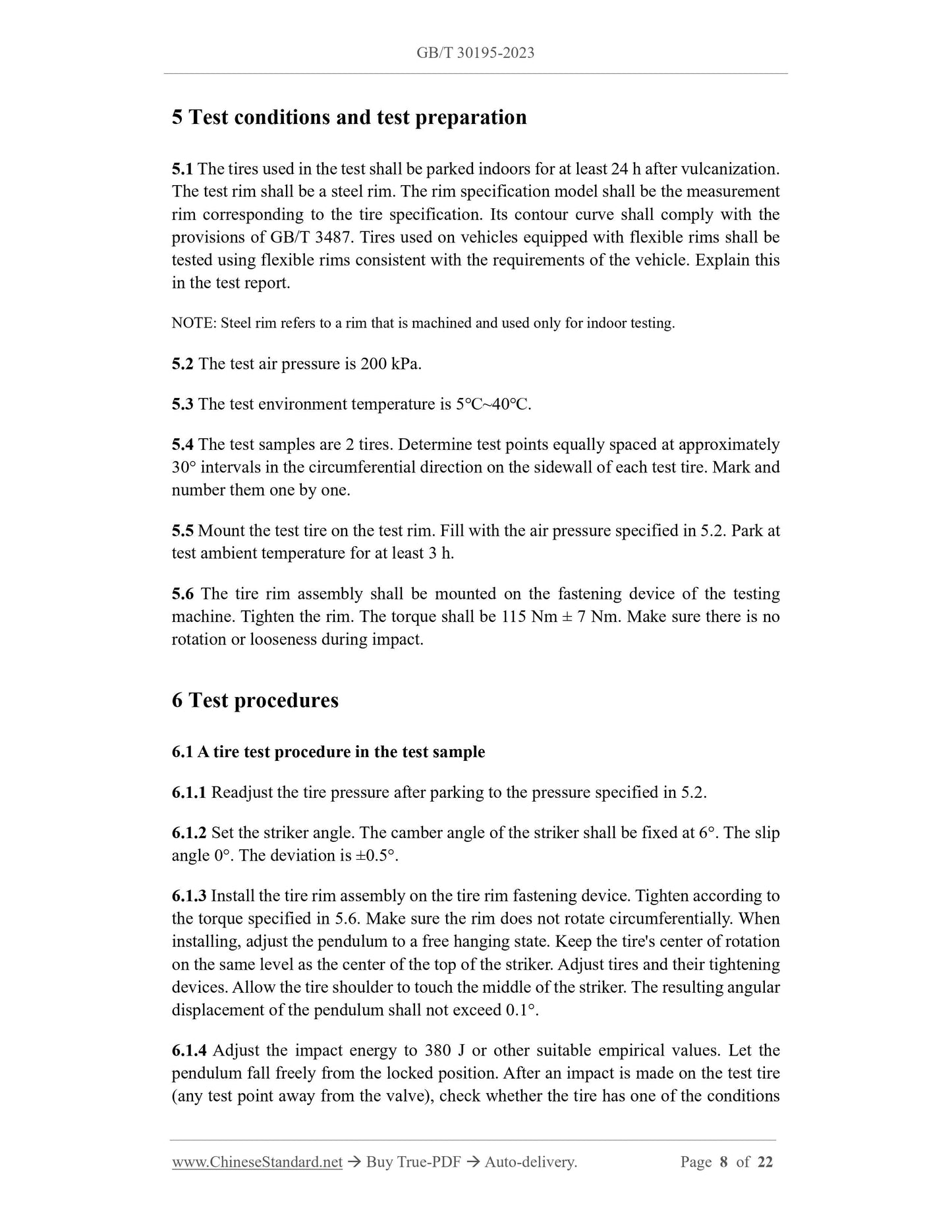
5.1 The tires used in the test shall be parked indoors for at least 24 h after vulcanization.
The test rim shall be a steel rim. The rim specification model shall be the measurement
rim corresponding to the tire specification. Its contour curve shall comply with the
provisions of GB/T 3487. Tires used on vehicles equipped with flexible rims shall be
tested using flexible rims consistent with the requirements of the vehicle. Explain this
in the test report.
NOTE: Steel rim refers to a rim that is machined and used only for indoor testing.
5.2 The test air pressure is 200 kPa.
5.3 The test environment temperature is 5℃~40℃.
5.4 The test samples are 2 tires. Determine test points equally spaced at approximately
30° intervals in the circumferential direction on the sidewall of each test tire. Mark and
number them one by one.
5.5 Mount the test tire on the test rim. Fill with the air pressure specified in 5.2. Park at
test ambient temperature for at least 3 h.
5.6 The tire rim assembly shall be mounted on the fastening device of the testing
machine. Tighten the rim. The torque shall be 115 Nm ± 7 Nm. Make sure there is no
rotation or looseness during impact.
6 Test procedures
6.1 A tire test procedure in the test sample
6.1.1 Readjust the tire pressure after parking to the pressure specified in 5.2.
6.1.2 Set the striker angle. The camber angle of the striker shall be fixed at 6°. The slip
angle 0°. The deviation is ±0.5°.
6.1.3 Install the tire rim assembly on the tire rim fastening device. Tighten according to
the torque specified in 5.6. Make sure the rim does not rotate circumferentially. When
installing, adjust the pendulum to a free hanging state. Keep the tire's center of rotation
on the same level as the center of the top of the striker. Adjust tires and their tightening
devices. Allow the tire shoulder to touch the middle of the striker. The resulting angular
displacement of the pendulum shall not exceed 0.1°.
6.1.4 Adjust the impact energy to 380 J or other suitable empirical values. Let the
pendulum fall freely from the locked position. After an impact is made on the test tire
(any test point away from the valve), check whether the tire has one of the conditions
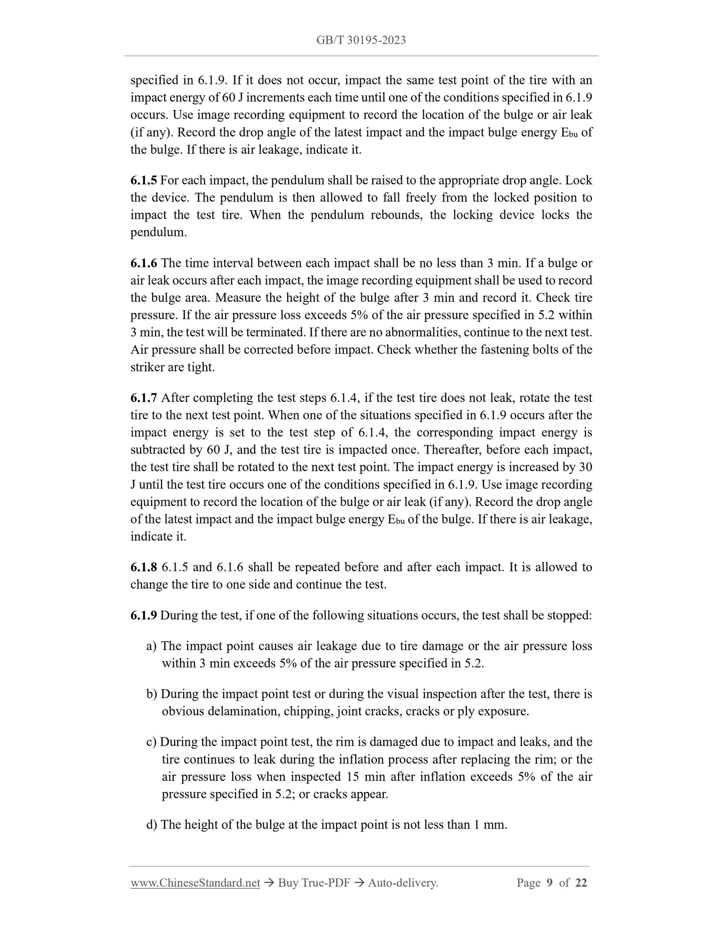
specified in 6.1.9. If it does not occur, impact the same test point of the tire with an
impact energy of 60 J increments each time until one of the conditions specified in 6.1.9
occurs. Use image recording equipment to record the location of the bulge or air leak
(if any). Record the drop angle of the latest impact and the impact bulge energy Ebu of
the bulge. If there is air leakage, indicate it.
6.1.5 For each impact, the pendulum shall be raised to the appropriate drop angle. Lock
the device. The pendulum is then allowed to fall freely from the locked position to
impact the test tire. When the pendulum rebounds, the locking device locks the
pendulum.
6.1.6 The time interval between each impact shall be no less than 3 min. If a bulge or
air leak occurs after each impact, the image recording equipment shall be used to record
the bulge area. Measure the height of the bulge after 3 min and record it. Check tire
pressure. If the air pressure loss exceeds 5% of the air pressure specified in 5.2 within
3 min, the test will be terminated. If there are no abnormalities, continue to the next test.
Air pressure shall be corrected before impact. Check whether the fastening bolts of the
striker are tight.
6.1.7 After completing the test steps 6.1.4, if the test tire does not leak, rotate the test
tire to the next test point. When one of the situations specified in 6.1.9 occurs after the