PayPal, credit cards. Download editable-PDF & invoice In 1 second!
GB/T 30036-2013 English PDF (GBT30036-2013)
Couldn't load pickup availability
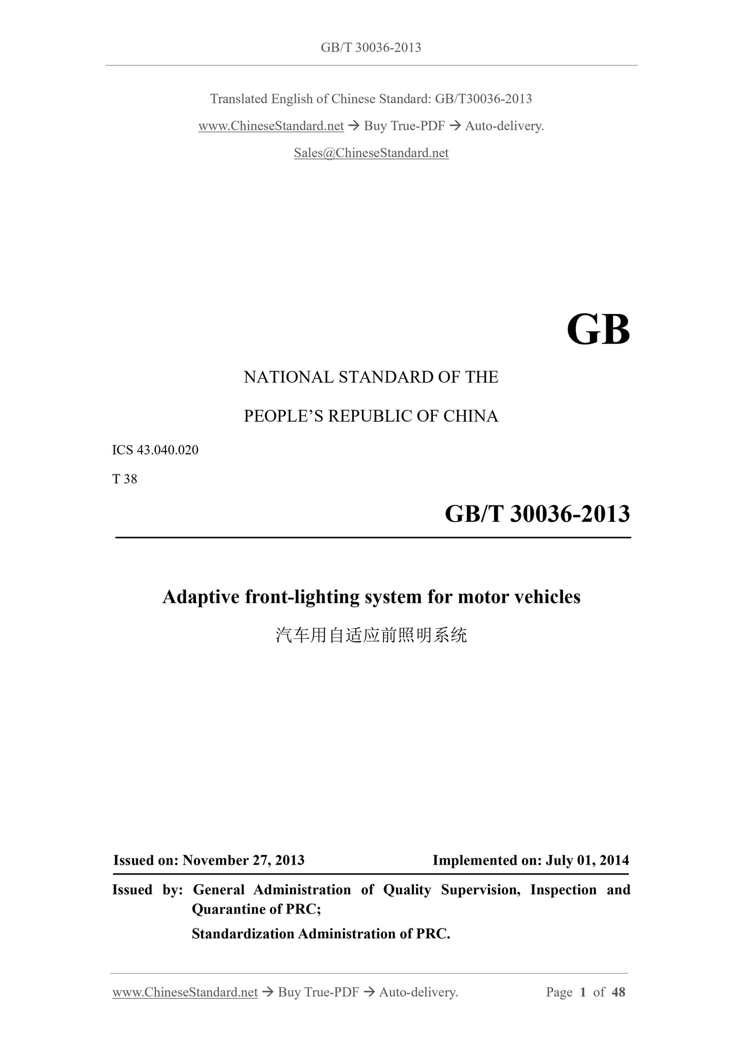
GB/T 30036-2013: Adaptive front-lighting system for motor vehicles
NATIONAL STANDARD OF THE
PEOPLE’S REPUBLIC OF CHINA
ICS 43.040.020
T 38
Adaptive front-lighting system for motor vehicles
ISSUED ON: NOVEMBER 27, 2013
IMPLEMENTED ON: JULY 01, 2014
Issued by: General Administration of Quality Supervision, Inspection and Quarantine of PRC;
Standardization Administration of PRC.
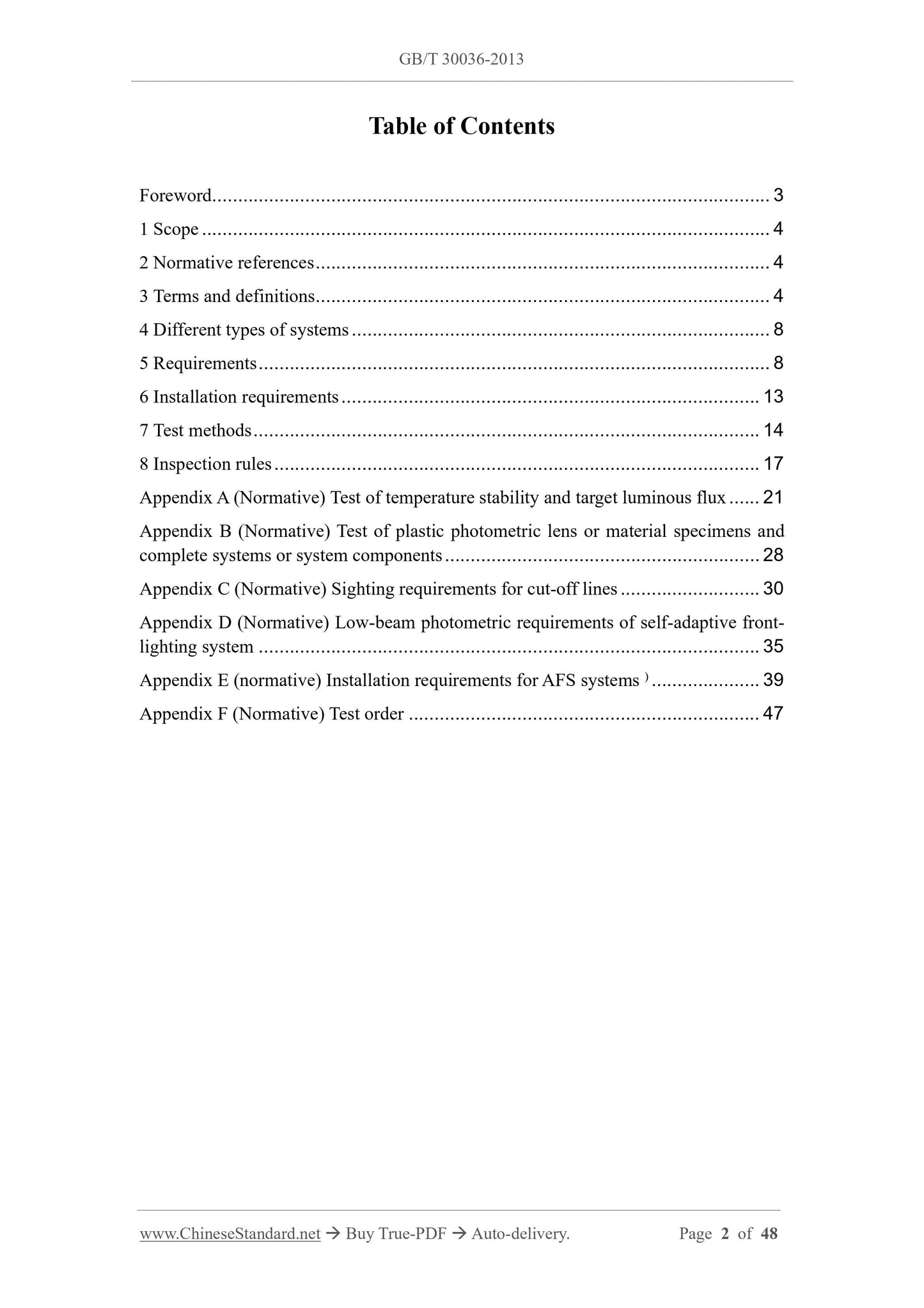
Table of Contents
Foreword ... 3
1 Scope ... 4
2 Normative references ... 4
3 Terms and definitions... 4
4 Different types of systems ... 8
5 Requirements ... 8
6 Installation requirements ... 13
7 Test methods ... 14
8 Inspection rules ... 17
Appendix A (Normative) Test of temperature stability and target luminous flux ... 21 Appendix B (Normative) Test of plastic photometric lens or material specimens and complete systems or system components ... 28
Appendix C (Normative) Sighting requirements for cut-off lines ... 30
Appendix D (Normative) Low-beam photometric requirements of self-adaptive front- lighting system ... 35
Appendix E (normative) Installation requirements for AFS systems ) ... 39 Appendix F (Normative) Test order ... 47
Adaptive front-lighting system for motor vehicles
1 Scope
This standard specifies the technical requirements, installation, test methods, inspection rules of adaptive front-lighting systems for motor vehicles (hereinafter referred to as "systems").
This standard applies to the adaptive front-lighting systems of categories M and N vehicles.
2 Normative references
The following documents are essential to the application of this document. For the dated documents, only the versions with the dates indicated are applicable to this document; for the undated documents, only the latest version (including all the amendments) is applicable to this standard.
GB 4599-2007 Motor vehicle headlamps equipped with filament lamps
GB 4785-2007 Prescription for installation of the external lighting and light- signaling devices for motor vehicles and their trailers
GB 15766.1 Filament lamps for road vehicles - Dimensional, electrical and luminous requirements
GB 21259-2007 Headlamps equipped with gas - discharge light sources for motor vehicle
GB 25991-2010 Automotive headlamps with LED light sources and/or LED
modules
ECE R37 Uniform provisions concerning the approval of filament lamps for use in approved lamp units on power-driven vehicles and of their trailers
ECE R99 Uniform provisions concerning the approval of gas-discharge light sources for use in approved gas-discharge lamp units of power-driven vehicles 3 Terms and definitions
The terms and definitions, as defined in GB 4599-2007, GB 4785-2007, GB 21259- 2007 and GB 25991-2010, as well as the following terms and definitions, apply to this document.
c) If the LED module is used as the light source, the system shall comply with the general requirements, color rendering, UV radiation resistance of the LED modules and power controller, which are specified in GB 25991-2010, as well as the temperature stability, light color stability, target luminous flux and other requirements in Appendix A of this standard.
5.1.4 The system shall comply with the provisions of A.2 and A.3.
5.1.5 If the optical lens of the system is made of plastic material, it shall also comply with the provisions of Appendix B.
5.1.6 For any mechanical, electro-mechanical or other device, which is combined with the lighting unit and used to control beam conversion, on a system or its components as designed to be switchable between high beam and low beam, its structure shall meet the following requirements:
a) It shall have sufficient strength, that under normal use conditions, even if it is subjected to vibration, it can still perform 50000 operations, without damage. b) The low beam or the high beam can be obtained at any time, without stopping between the two beams or other uncertain positions. If these requirements cannot be met, then its state shall meet the requirements of c) below.
c) In the event of a failure, the system shall be able to automatically obtain low beams, OR by turning off, dimming, sighting down, and/or functional substitution, to make the photometric value of the IIIb area be not greater than 1.5 lx, meanwhile the luminosity of at least one point on the Emax line segment is not less than 4 lx. d) The user can NEITHER change the shape or position of the moving parts with ordinary tools, NOR affect the switching device.
5.1.7 The designed system can provide a failure signal, when a light source and/or an LED module fails. The installation of the failure signal indicator shall comply with the requirements of E.2.7.5.2.
5.1.8 The replaceable light source, which is used by the system, shall be easy to install AND can be installed in the correct position, even in the dark.
5.1.9 The system shall not generate radiation or power line conduction disturbance, which may cause malfunction of other electrical/electronic systems of the vehicle 2). 5.2 Light color of the system
It shall be white; its chromaticity characteristics shall meet the requirements of GB 4785-2007.
2 The consistency of radiated or power line conducted disturbance requirements is related to the specific vehicle type.
5.3 Photometric performance
5.3.1 General provisions
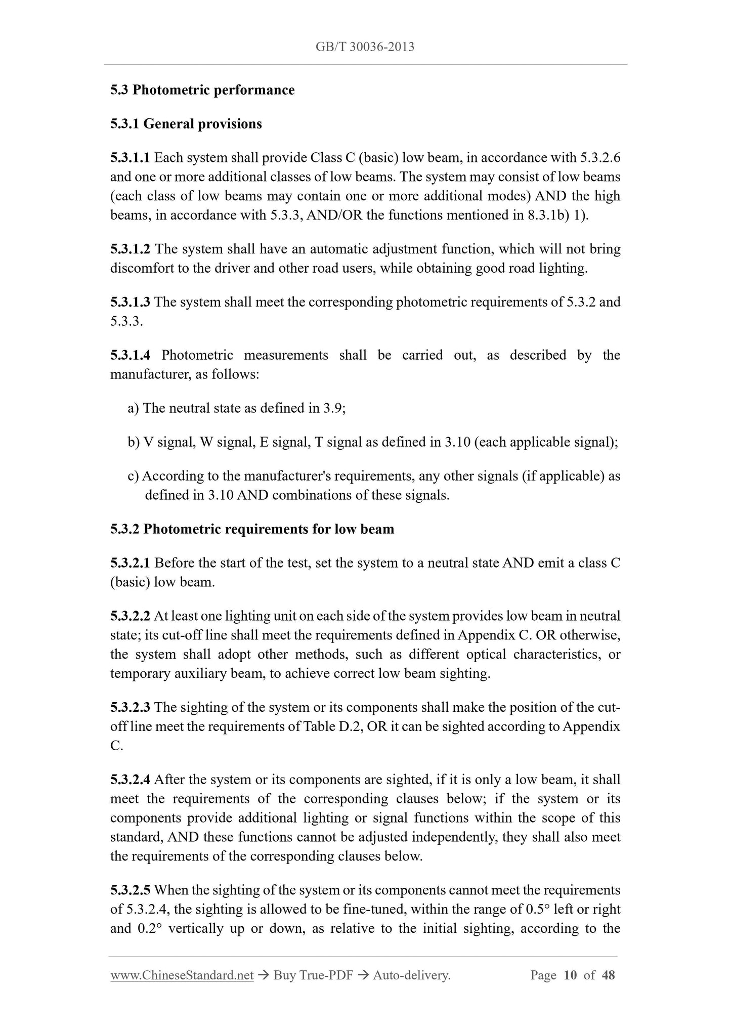
5.3.1.1 Each system shall provide Class C (basic) low beam, in accordance with 5.3.2.6 and one or more additional classes of low beams. The system may consist of low beams (each class of low beams may contain one or more additional modes) AND the high beams, in accordance with 5.3.3, AND/OR the functions mentioned in 8.3.1b) 1). 5.3.1.2 The system shall have an automatic adjustment function, which will not bring discomfort to the driver and other road users, while obtaining good road lighting. 5.3.1.3 The system shall meet the corresponding photometric requirements of 5.3.2 and 5.3.3.
5.3.1.4 Photometric measurements shall be carried out, as described by the manufacturer, as follows:
a) The neutral state as defined in 3.9;
b) V signal, W signal, E signal, T signal as defined in 3.10 (each applicable signal); c) According to the manufacturer's requirements, any other signals (if applicable) as defined in 3.10 AND combinations of these signals.
5.3.2 Photometric requirements for low beam
5.3.2.1 Before the start of the test, set the system to a neutral state AND emit a class C (basic) low beam.
5.3.2.2 At least one lighting unit on each side of the system provides low beam in neutral state; its cut-off line shall meet the requirements defined in Appendix C. OR otherwise, the system shall adopt other methods, such as different optical characteristics, or temporary auxiliary beam, to achieve correct low beam sighting.
5.3.2.3 The sighting of the system or its components shall make the position of the cut- off line meet the requirements of Table D.2, OR it can be sighted according to Appendix C.
5.3.2.4 After the system or its components are sighted, if it is only a low beam, it shall meet the requirements of the corresponding clauses below; if the system or its components provide additional lighting or signal functions within the scope of this standard, AND these functions cannot be adjusted independently, they shall also meet the requirements of the corresponding clauses below.
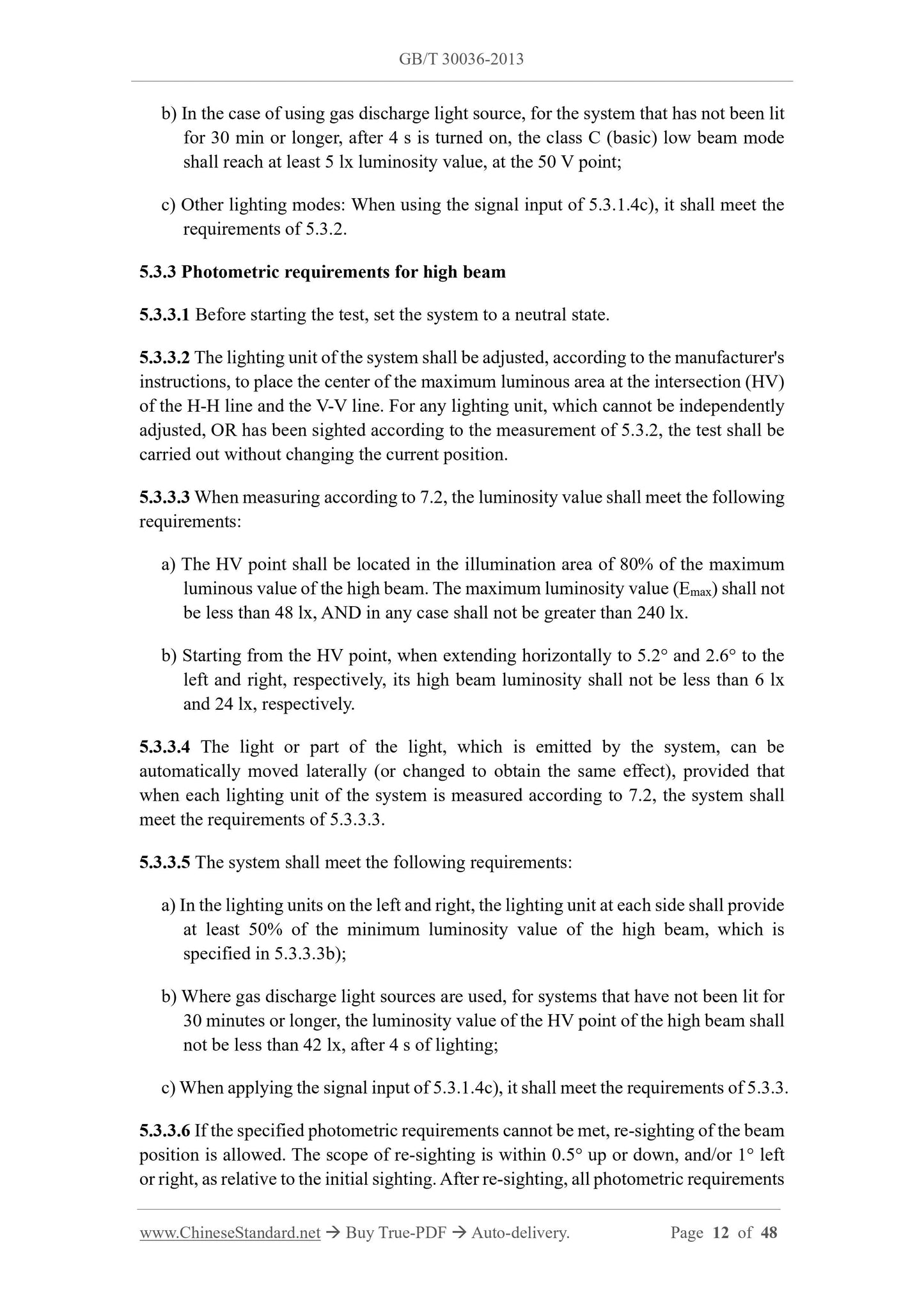
5.3.2.5 When the sighting of the system or its components cannot meet the requirements of 5.3.2.4, the sighting is allowed to be fine-tuned, within the range of 0.5° left or right and 0.2° vertically up or down, as relative to the initial sighting, according to the b) In the case of using gas discharge light source, for the system that has not been lit for 30 min or longer, after 4 s is turned on, the class C (basic) low beam mode shall reach at least 5 lx luminosity value, at the 50 V point;
c) Other lighting modes: When using the signal input of 5.3.1.4c), it shall meet the requirements of 5.3.2.
5.3.3 Photometric requirements for high beam
5.3.3.1 Before starting the test, set the system to a neutral state.
5.3.3.2 The lighting unit of the system shall be adjusted, according to the manufacturer's instructions, to place the center of the maximum luminous area at the intersection (HV) of the H-H line and the V-V line. For any lighting unit, which cannot be independently adjusted, OR has been sighted according to the measurement of 5.3.2, the test shall be carried out without changing the current position.
5.3.3.3 When measuring according to 7.2, the luminosity value shall meet the following requirements:
a) The HV point shall be located in the illumination area of 80% of the maximum luminous value of the high beam. The maximum luminosity value (Emax) shall not be less than 48 lx, AND in any case shall not be greater than 240 lx.
b) Starting from the HV point, when extending horizontally to 5.2° and 2.6° to the left and right, respectively, its high beam luminosity shall not be less than 6 lx and 24 lx, respectively.
5.3.3.4 The light or part of the light, which is emitted by the system, can be automatically moved laterally (or changed to obtain the same effect), provided that when each lighting unit of the system is measured according to 7.2, the system shall meet the requirements of 5.3.3.3.
5.3.3.5 The system shall meet the following requirements:
a) In the lighting units on the left and right, the lighting unit at each side shall provide at least 50% of the minimum luminosity value of the high beam, which is specified in 5.3.3.3b);
b) Where gas discharge light sources are used, for systems that have not been lit for 30 minutes or longer, the luminosity value of the HV point of the high beam shall not be less than 42 lx, after 4 s of lighting;
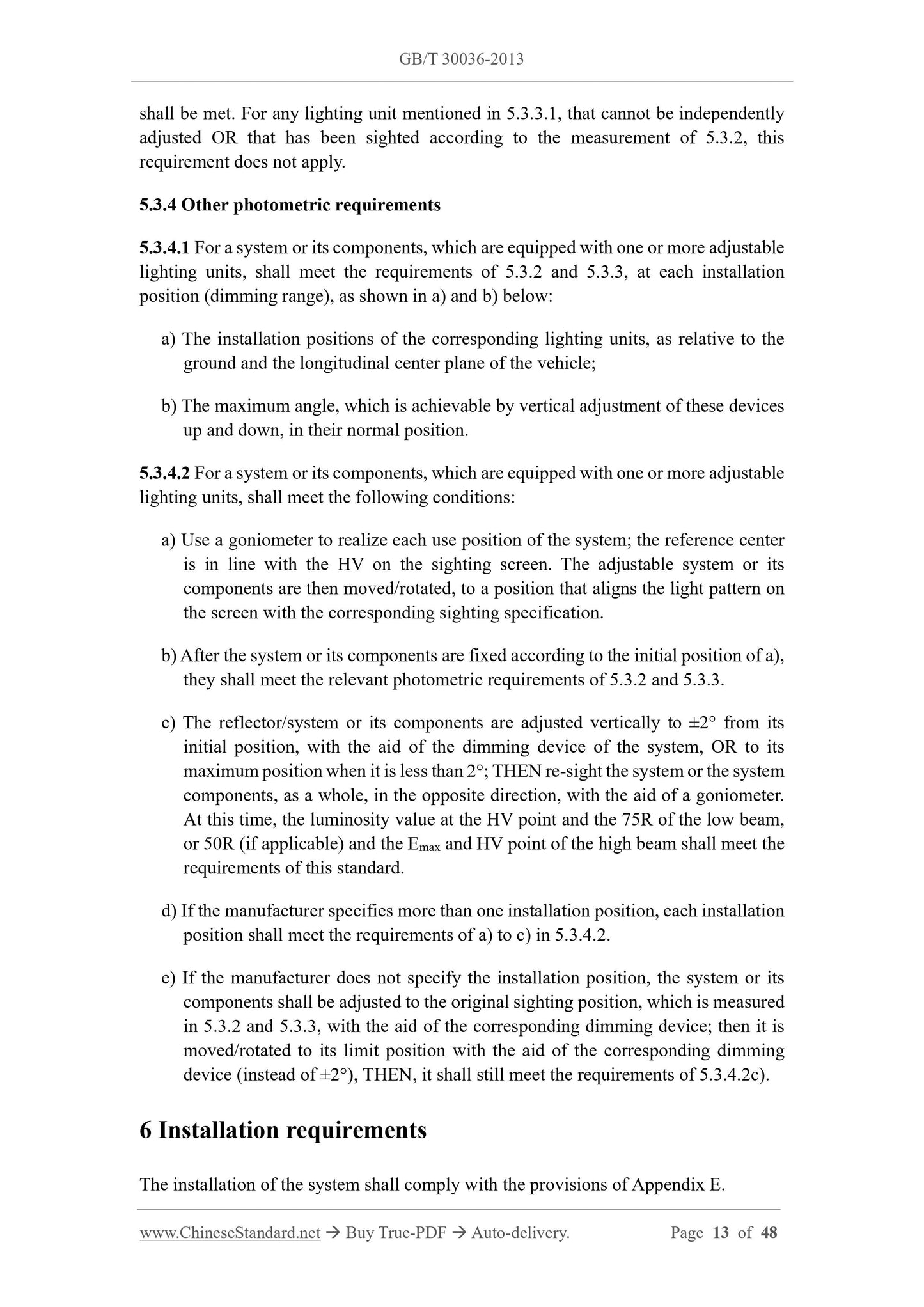
c) When applying the signal input of 5.3.1.4c), it shall meet the requirements of 5.3.3. 5.3.3.6 If the specified photometric requirements cannot be met, re-sighting of the beam position is allowed. The scope of re-sighting is within 0.5° up or down, and/or 1° left or right, as relative to the initial sighting. After re-sighting, all photometric requirements shall be met. For any lighting unit mentioned in 5.3.3.1, that cannot be independently adjusted OR that has been sighted according to the measurement of 5.3.2, this requirement does not apply.
5.3.4 Other photometric requirements
5.3.4.1 For a system or its components, which are equipped with one or more adjustable lighting units, shall meet the requirements of 5.3.2 and 5.3.3, at each installation position (dimming range), as shown in a) and b) below:
a) The installation positions of the corresponding lighting units, as relative to the ground and the longitudinal center plane of the vehicle;
b) The maximum angle, which is achievable by vertical adjustment of these devices up and down, in their normal position.
5.3.4.2 For a system or its components, which are equipped with one or more adjustable lighting units, shall meet the following conditions:
a) Use a goniometer to realize each use position of the system; the reference center is in line with the HV on the sighting screen. The adjustable system or its components are then moved/rotated, to a position that aligns the light pattern on the screen with the corresponding sighting specification.
b) After the system or its components are fixed according to the initial position of a), they shall meet the relevant photometric requirements of 5.3.2 and 5.3.3. c) The reflector/system or its components are adjusted vertically to ±2° from its initial position, with the aid of the dimming device of the system, OR to its maximum position when it is less than 2°; THEN re-sight the system or the system components, as a whole, in the opposite direction, with the aid of a goniometer. At this time, the luminosity value at the HV point and the 75R of the low beam, or 50R (if applicable) and the Emax and HV point of the high beam shall meet the requirements of this standard.
d) If the manufacturer specifies more than one installation position, each installation position shall meet the requirements of a) to c) in 5.3.4.2.
e) If the manufacturer does not specify the installation position, the system or its components shall be adjusted to the original sighting position, which is measured in 5.3.2 and 5.3.3, with the aid of the corresponding dimming device; then it is moved/rotated to its limit position with the aid of the corresponding dimming device (instead of ±2°), THEN, it shall still meet the requirements of 5.3.4.2c). 6 Installation requirements
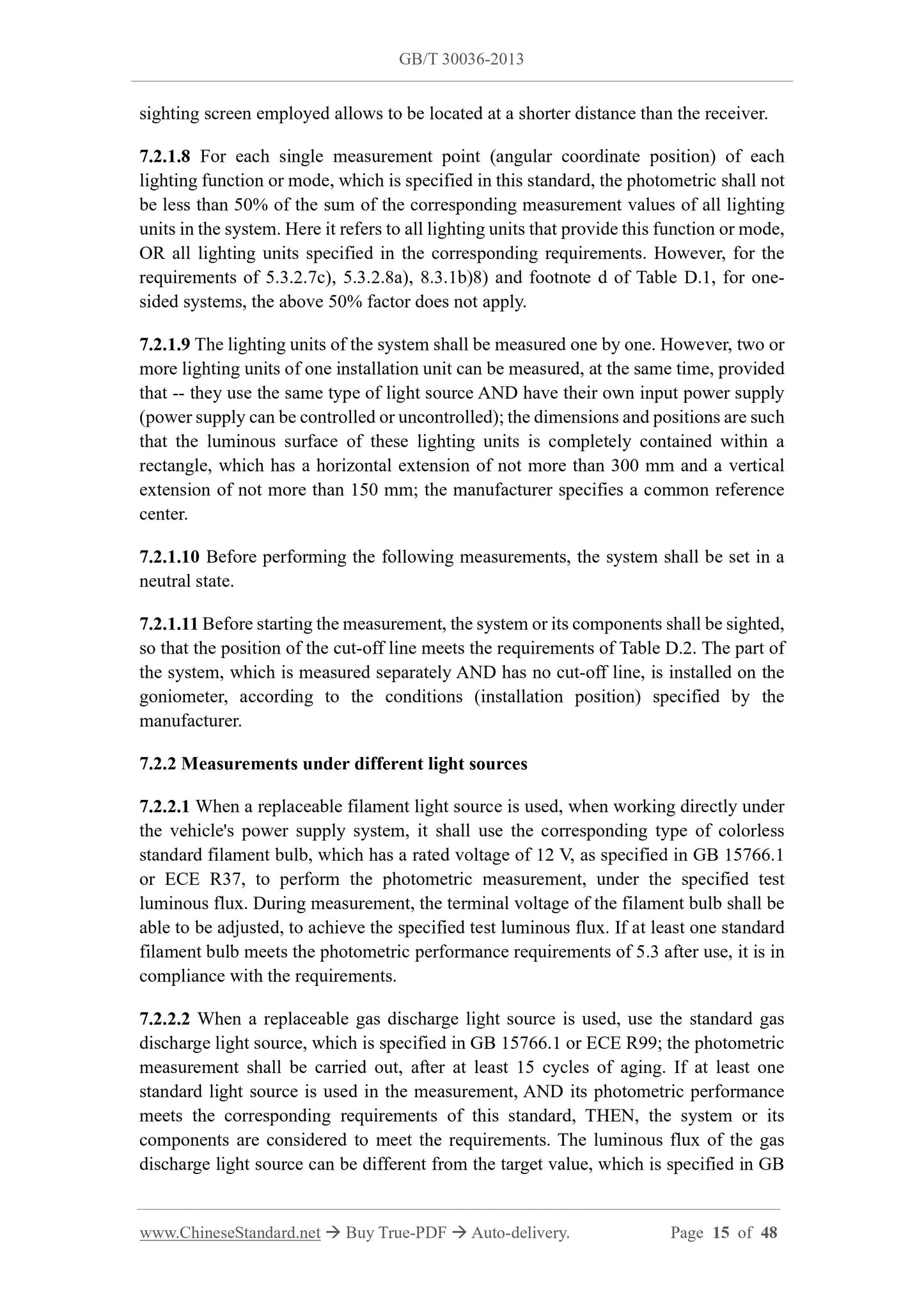
The installation of the system shall comply with the provisions of Appendix E. sighting screen employed allows to be located at a shorter distance than the receiver. 7.2.1.8 For each single measurement point (angular coordinate position) of each lighting function or mode, which is specified in this standard, the photometric shall not be less than 50% of the sum of the corresponding measurement values of all lighting units in the system. Here it refers to all lighting units that provide this function or mode, OR all lighting units specified in the corresponding requirements. However, for the requirements of 5.3.2.7c), 5.3.2.8a), 8.3.1b)8) and footnote d of Table D.1, for one- sided systems, the above 50% factor does not apply.
7.2.1.9 The lighting units of the system shall be measured one by one. However, two or more lighting units of one installation unit can be measured, at the same time, provided that -- they use the same type of light source AND have their own input power supply (power supply can be controlled or uncontrolled); the dimensions and positions are such that the luminous surface of these lighting units is completely contained within a rectangle, which has a horizontal extension of not more than 300 mm and a vertical extension of not more than 150 mm; the manufacturer specifies a common reference center.
7.2.1.10 Before performing the following measurements, the system shall be set in a neutral state.
7.2.1.11 Before starting the measurement, the system or its components shall be sighted, so that the position of the cut-off line meets the requirements of Table D.2. The part of the system, which is measured separately AND has no cut-off line, is installed on the goniometer, according to the conditions (installation position) specified by the manufacturer.
7.2.2 Measurements under different light sources
7.2.2.1 When a replaceable filament light source is used, when working directly under the vehicle's power supply system, it shall use the corresponding type of colorless standard filament bulb, which has a rated voltage of 12 V, as specified in GB 15766.1 or ECE R37, to perform the photometric measurement, under the specified test luminous flux. During measurement, the terminal voltage of the filament bulb shall be able to be adjusted, to achieve the specified test luminous flux. If at least one standard filament bulb meets the photometric performance requirements of 5.3 after use, it is in compliance with the requirements.
7.2.2.2 When a replaceable gas discharge light source is used, use the standard gas discharge light source, which is specified in GB 15766.1 or ECE R99; the photometric measurement shall be carried out, after at least 15 cycles of aging. If at least one standard light source is used in the measurement, AND its photometric performance meets the corresponding requirements of this standard, THEN, the system or its components are considered to meet the requirements. The luminous flux of the gas discharge light source can be different from the target value, which is specified in GB 15766.1 or ECE R99. At this time, the measured photometric value shall be corrected in time; the correction factor is 0.7.
7.2.2.3 When using a non-replaceable light source which works directly under the vehicle power supply system, all measurements shall be made at 6.75 V, 13.5 V, 28.0 V or the voltage specified by the manufacturer. Photometric measurements shall be corrected by a factor of 0.7.
7.2.2.4 When a replaceable or non-replaceable light source is used, if it is completely controlled by the system AND is independent of the power supply voltage of the vehicle, or the voltage is input from a special power supply, THEN, the input voltage of the system/power supply shall be input, according to the test voltage specified in 7.2.2.3. end. If necessary, a dedicated power supply for measurement is provided by the manufacturer. Unless the correction factor has been used in accordance with 7.2.2.2, the photometric measurement shall be corrected by a factor of 0.7.
7.2.2.5 When the system adopts LED module, if there are no other special provisions, the measurement voltage shall be corresponding 6.75 V, 13.5 V or 28.0 V. If there is an electronic light source controller LED module, measure it according to the voltage specified by the manufacturer. The specific test shall be as specified in 7.2.4. Photometric measurements shall be corrected by a factor of 0.7.
7.2.3 Measurement of bending mode
When the system or its components provide a bending mode, the requirements of 5.3.2 and/or 5.3.3 apply to all lighting states of the system or its components, under various turning radii of the vehicle. The following procedures shall be followed, for the detection of high and low beam in the bending mode of the curve:
a) The system shall be subjected to the following tests in the neutral state. It shall also include the following detections (if applicable), in the state of the minimum turning radius of the vehicle, in both directions when the signal generator is used: 1) Without additional horizontal re-sighting, test whether the bending modes of category 1 and category 2 meet the requirements of 5.3.2.7b) and 5.3.2.7c), as well as part of the requirements of 5.3.2.7e): As relative to the system reference axis, at each position within the range of 5° to the left and 0.3° upward from the H-H line, as well as each position within the range of more than 5° to the left and 0.57° upward, the luminosity value are not more than 1 lx. The luminosity of the IIIb area is not required;
2) According to the following different situations (if any), test whether it meets the requirements of 5.3.2.7a) and 5.3.3:
(1) In the case of category 2 bending mode, additional horizontal re-sighting shall not be performed;
passed the type inspection or consistency inspection.
8.3 Type inspection
8.3.1 The manufacturer shall provide:
a) The system drawings sufficient to identify the type shall be in triplicate. If applicable, the drawings shall indicate the geometric positions of each lighting unit, as relative to the ground and the longitudinal center plane of the vehicle, after loading, including the reference axis used for the test, the reference point on the photometric lens, as well as any optical features.
b) A concise system technical specification, which contains:
1) The lighting functions and modes provided by the system;
2) The other front-lighting functions and front signaling functions, which are provided by any lamps combined, compounded or mixed in the lighting unit of the system;
3) The technical characteristics of the lighting units, which provide these functional modes and the signals, which perform these functions;
4) If any, the type of bending mode adopted;
5) If any, according to Table D.6, the applicable auxiliary data of Class E low beam;
6) If any, according to Appendix D, the setting of applicable Class W low beam; 7) Lighting units, which provide or assist to provide part or multi-part low beam cut-off line;
8) A lighting unit, which provides the cu...
Share