1
/
of
6
www.ChineseStandard.us -- Field Test Asia Pte. Ltd.
GB/T 30020-2023 English PDF (GB/T30020-2023)
GB/T 30020-2023 English PDF (GB/T30020-2023)
Regular price
$200.00
Regular price
Sale price
$200.00
Unit price
/
per
Shipping calculated at checkout.
Couldn't load pickup availability
GB/T 30020-2023: Test method for determining defects of glass - Photo elastic scanning method
Delivery: 9 seconds. Download (and Email) true-PDF + Invoice.Get Quotation: Click GB/T 30020-2023 (Self-service in 1-minute)
Newer / historical versions: GB/T 30020-2023
Preview True-PDF
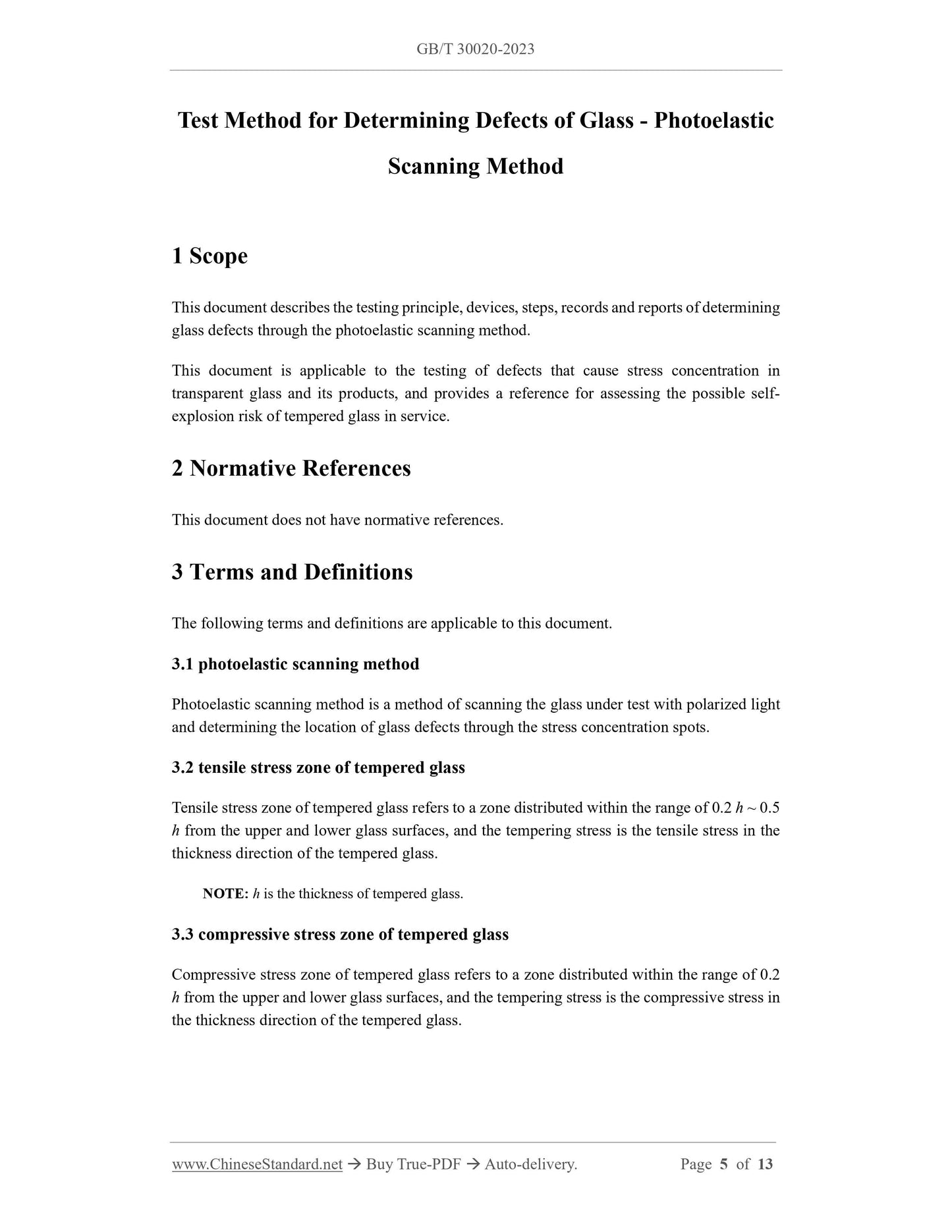
Scope
This document describes the testing principle, devices, steps, records and reports of determiningglass defects through the photoelastic scanning method.
This document is applicable to the testing of defects that cause stress concentration in
transparent glass and its products, and provides a reference for assessing the possible self-
explosion risk of tempered glass in service.
Basic Data
| Standard ID | GB/T 30020-2023 (GB/T30020-2023) |
| Description (Translated English) | Test method for determining defects of glass - Photo elastic scanning method |
| Sector / Industry | National Standard (Recommended) |
| Classification of Chinese Standard | Q30 |
| Classification of International Standard | 81.040.10 |
| Word Count Estimation | 9,989 |
| Date of Issue | 2023-03-17 |
| Date of Implementation | 2023-10-01 |
| Older Standard (superseded by this standard) | GB/T 30020-2013 |
| Issuing agency(ies) | State Administration for Market Regulation, China National Standardization Administration |
Share